Humidification and air cleaning system
Hi, Geektimes!
In my last publication, I shared my thoughts on the modernization of the air-conditioning system installed in my apartment with fresh air supply by adding humidification during the cold season.
Considering all these nuances, I made a decision about the natural tests in the cold season, when the outdoor temperature will be at least 0 - +5 degrees.

Author KDPV - Vasya Lozhkin .
I inform you that tests are being carried out, some of which I already think of sharing here and now, since the necessary equipment for automation is on the way, winter is nearing its end and the full results of such a decision can most likely be assessed only in the next heating season.
Will flow / will not flow
In the fall, a fogging system was ordered in the “Celestial”, for a month it was delivered to me in the city. Included is a 5-meter flexible tube, 10 nozzles, tees connecting the tube and foggers, connecting adapters for quick connection to the water supply. First of all, I checked how the sprayer and the water flow work. One tip forms a cloud of fine-fine rain, starting from the thinnest trickle (connected instead of a watering can of a shower) and up to the maximum of an open tap, the flow can and does not change, but the formed cloud remains in the same range - approximately 800 mm apart. angle of 30 degrees. Flow was measured by a timer - in 30 minutes about 2.5 liters gathered in a bucket, measured with a 3-liter can.
The next stage is to check how the cloud of fog spreads inside the channel block, in the air ducts and grilles, how the heat exchanger fins behave.
')
Experimental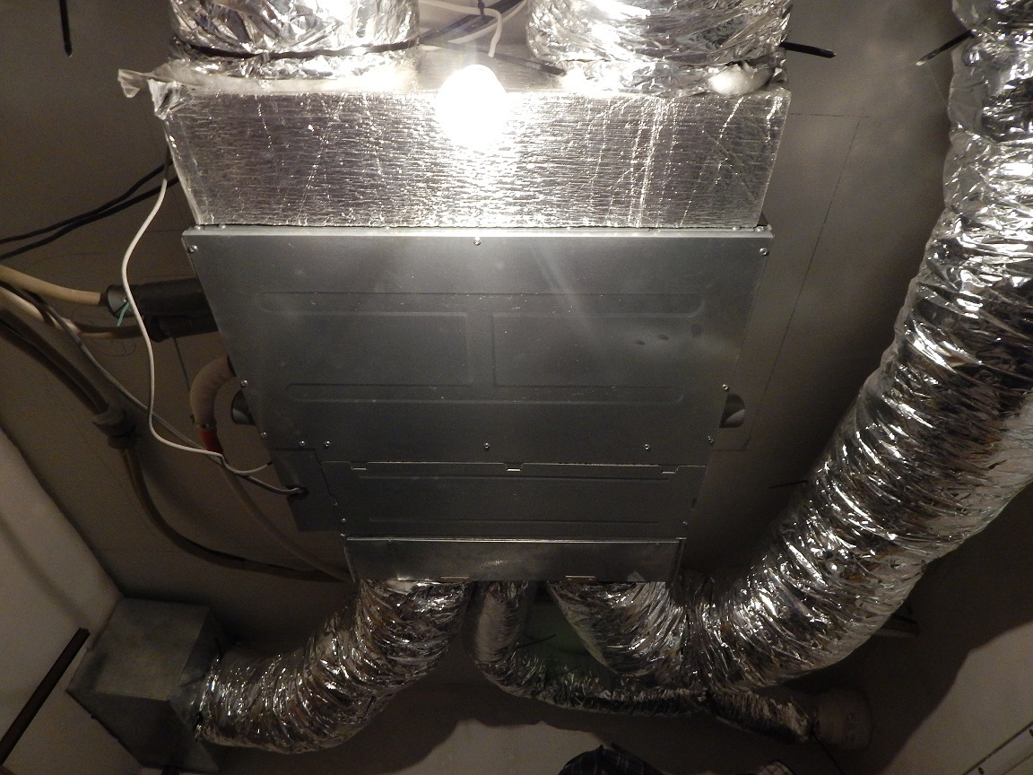
Bottom panel removed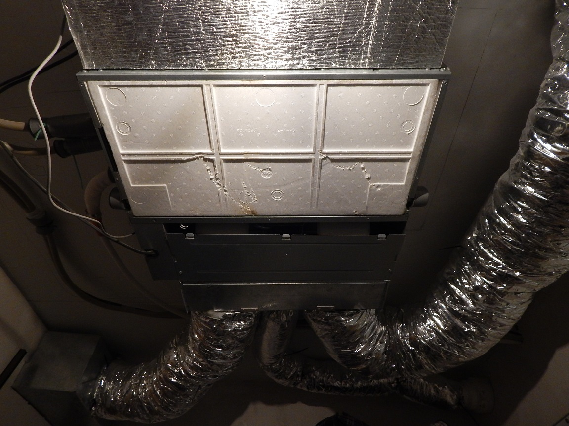
Condensate collection tray removed
Stickers sprinkled with adhesive tape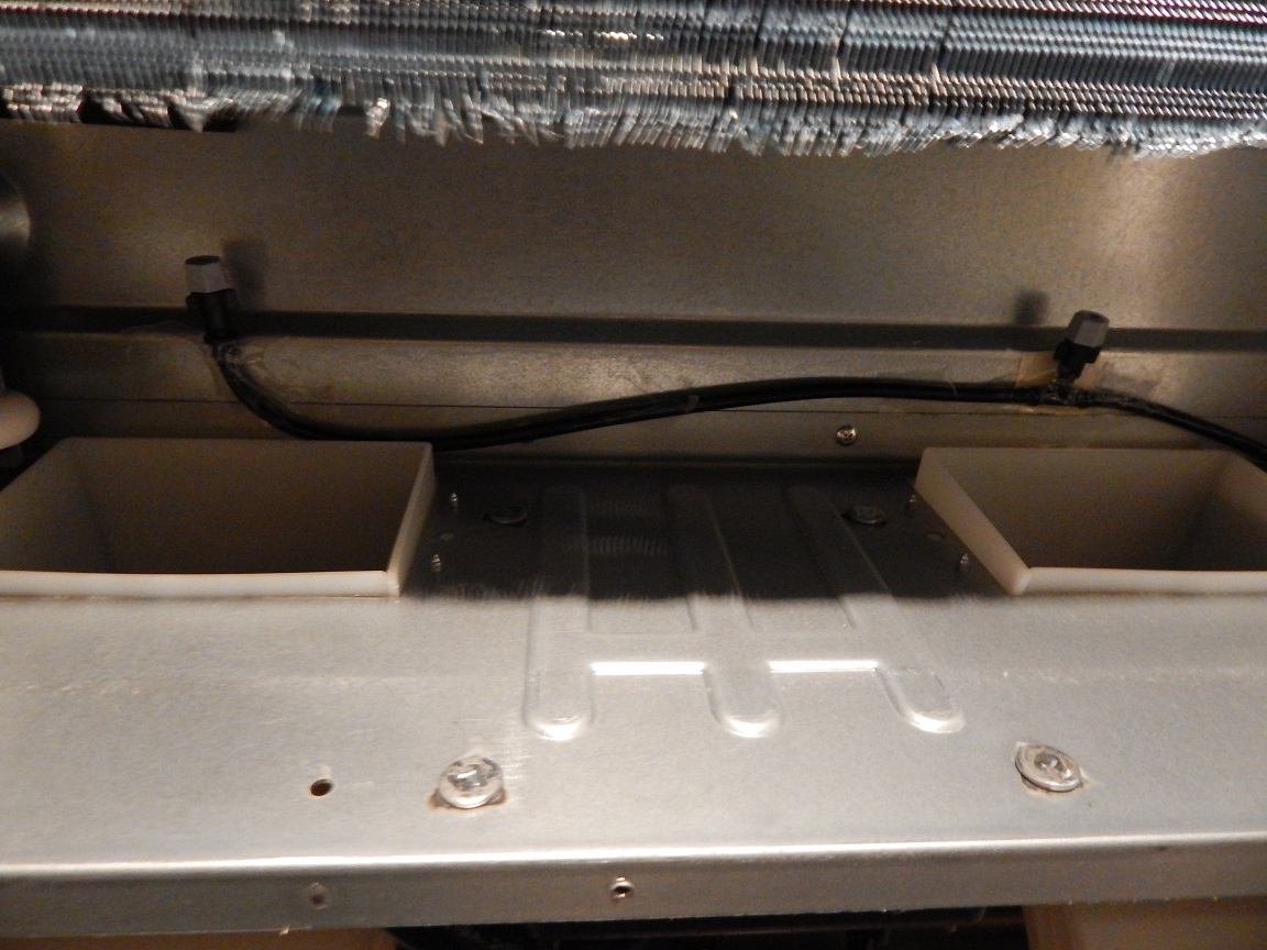
Since we didn’t want to immediately upgrade the internal unit, we didn’t want to connect the tube to the tees to the inside of the air conditioner through the plug in the foam tray on the left as we move along the air.
He opened the water at first just like that - both sprayers functioned as needed, did not notice extraneous drips.
Set in place a condensate collection tray. I started the indoor unit to the ventilation mode (fans only) at the minimum speed and again opened the water. Visually, nothing is visible, since everything is closed - but it was clear from the sound that the sprayers supplied water. By the way, the noise from them is even greater than from the operation of the air conditioner at the minimum speed.
The tap was open for 15 minutes, i.e. About 2.5 liters of cold water was supplied to the air conditioner. The indoor unit worked for 5 minutes at minimum, 5 minutes at medium and 5 at maximum fan speeds. All this time, “waving his hands” behind the heat exchanger at the outlet of the indoor unit, holding a paper napkin, etc. Somewhere in the 10th minute (before switching to the maximum speed), the lower half of the heat exchanger became wet, during which time the water level in the pan to the right rose to about 7 mm. At the 15th minute, water began to drip from the nozzle with a missing cap, i.e. the water level in the pan was already quite high (about 10 mm in the right corner). I went off the tap with the flow, I heard how the condensation pump started working - the float worked. The pump worked for 10 minutes, turned off the ventilation mode with water.
In principle, I consider the experiment successful, since the main fears have not been confirmed and the water does not leave the air conditioner.
Theoretical part
An updated sketch with the location of the equipment in the ceiling space of the dressing room serving the children's room and bedroom:
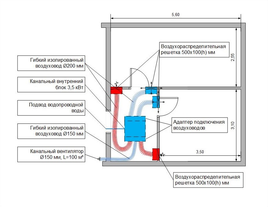
The performance of the air conditioner indoor unit by air, according to the manufacturer's documentation at a minimum speed of 425 m3 / h.
The parameters of the premises in question in the context of air-supplied air at minimum speed
| volume, m3 | Air from the air conditioner, m3 | Multiplicity | Fresh air, m3 | |
|---|---|---|---|---|
| Children's | 36 | 200 | 5.6 | 50 |
| Bedroom | 27 | 200 | 7.4 | 50 |
These volumes were obtained by me with the installation of a flow regulator behind the supply grille of the bedroom, since without a regulator due to the lower resistance of the feed and return air ducts of the bedroom, the ratio was 220/180. Due to the large heat leakage and heat loss in the bedroom (3-sash window), it was decided to split the air flow equally, and not by multiplicity. Data on the volume of fresh air can not be measured by any method known to me, therefore, obtained by simple calculations.
From the table, you can additionally calculate that the approximate time of the complete treatment of the air conditioner for the rooms will be 8 and 11 minutes, and 100% airing - the supply of fresh air in the full volume of rooms 32 and 43 minutes.
First moisturizing
Of course, after receiving positive results that the fine rain does not go beyond the air conditioner, it’s very “worn hands” to conduct a more thorough check. Preparatory work, the actual measurements and recording the results in the table took half of my day off. Air distribution grilles and a regulator were removed. Disconnected from the power supply fan mix fresh air into the system. A canalnik is drilled, a tube is inserted inside and sprayers are screwed on the platforms / screeds. I honestly forgot to take a picture of how it all looks inside, but it doesn’t differ much from a photo with scotch tape. I took a Testo 410-2 instrumentometer from my colleagues , and they took measurements. Measurement technique - 5 measurements per hole 100x500mm in size, 10 seconds per point. Measurements were carried out on 2 inlets and exhaust grille (tributaries to the nursery and bedroom, extract from the bedroom), it was difficult to get to the 2nd exhaust grille - it is above the cabinet and in front of her bags with toys, and in the room at that time youngest son slept. He served cold water from the system, tried to supply / disconnect water in cycles of 10 minutes approximately from 12:35. The first measurement before the water supply showed a moisture content of 41.4% on the supply grille in the bedroom. The results of the work in the table below.
| Name | Time | Humidity | Speed | Temperature |
|---|---|---|---|---|
| 1. Bedroom Inflow | 12:36 | 50.2 | 1,3 | 22.2 |
| 2. Bedroom hood | 12:38 | 43.6 | 1.2 | 22.9 |
| 3. Children's influx | 12:39 | 49,6 | 1.0 | 22.2 |
| 4. Bedroom Inflow | 12:45 | 53.2 | 1,3 | 22.5 |
| 5. Bedroom hood | 12:47 | 47.9 | 1.2 | 23.5 |
| 6. Children's influx | 12:49 | 46.5 | 1.1 | 23.1 |
| 7. Bedroom Inflow | 12:56 | 57,8 | 1.5 | 21.7 |
| 8. Bedroom hood | One to two | 50.6 | 1.2 | 23.4 |
| 9. Children's influx | 13:01 | 51.8 | 1.1 | 22.4 |
| 10. Bedroom Inflow | 13:05 | 56,8 | 1.4 | 21.8 |
| 11. Bedroom hood | 13:06 | 51.9 | 1.2 | 23.1 |
| 12. Children's influx | 13:08 | 49.0 | 1,3 | 22.5 |
| 13. Bedroom Inflow | 13:16 | 58.2 | 1.4 | 22.0 |
| 14. Bedroom hood | 13:17 | 51.8 | 1.2 | 23.5 |
| 15. Children's influx | 13:19 | 51.8 | 1.1 | 22.4 |
| 16. Bedroom Inflow | 13:27 | 60.4 | 1.5 | 21.6 |
| 17. Bedroom hood | 13:29 | 56,1 | 1.2 | 23.2 |
| 18. Children's influx | 13:30 | 51.4 | 1,3 | 22.3 |
| 19. Bedroom Inflow | 13:36 | 59.5 | 1.4 | 22.4 |
| 20. Bedroom hood | 13:37 | 54.3 | 1.2 | 23.8 |
| 21. Children's influx | 13:39 | 53.3 | 1,3 | 22.3 |
| 22. Bedroom Inflow | 1:48 pm | 61.4 | 1.5 | 21.7 |
| 23. Bedroom hood | 13:50 | 57.1 | 1.2 | 23.4 |
| 24. Children's influx | 13:52 | 56.3 | 1.4 | 22.5 |
Red text - water is not supplied to the indoor unit, blue text is supplied. In fact, the measurements were done much more; in 10 minutes of supplying or not supplying water to the sprayers, I managed to measure all the grids in a row twice, but for analytics of the results they are of no value. I also did not include data on the on / off of the condensation pump in the presented table - everything is simple, the automation of the indoor unit works according to the following algorithm: float drawdown - displaying a message on the display - pump operation 10 minutes.
It is clear from the above table that in an hour and a half of the fogging system, the humidity level in the rooms rose to an acceptable 55-60% with a slightly comfortable 40% (played a role of +5 degrees outside), the temperature of the air passing over the pan and through a moistened heat exchanger with cold tap water drops by 1-2 degrees, which is acceptable.
Trials continue
Currently conducted 4, similar to the first test. The changes mainly concerned the time of water supply / disconnection - 10/10, 5/15, 5/10, 10/20, the temperature of the outside air and the dependence of the humidity inside the apartment also played a role, in all tests for an hour and a half the humidity in the rooms increased over 50%. The best indicators of the stability of the humidification system were shown by the time format of 5/10 cycles, i.e. 5 minutes water supply for fogging, 10 minutes just work on ventilation, but in this case, about 3.3 liters of water per hour is drained into the sewer system by a pump. It is also very noticeable that the right half of the channel unit humidifies the air more (the one that supplies air to the bedroom). My opinion is that this is due to the fact that the air passes through not only through a moist heat exchanger, but also above the tray, where more water is collected.
In this connection, I think to remove one of the foggers from the indoor unit, that is, to leave one of the two, and leave the one on the left (in the direction of air movement). Thus, the air for the nursery will be humidified passing through the heat exchanger, the air for the bedroom will be moistened with water in the pan and the amount of water supplied to the air conditioner will be halved.
Arduino
As I wrote above, the arduino equipment is on the way, but unfortunately, the iron part will not be included in this publication yet.
I chose the necessary equipment for myself:
- DHT22 / AM2302, Temperature and humidity sensor - 3 pcs. One should be installed after the heater in order to control the temperature of fresh air supplied to the system from the street, two sensors should be installed in the supply and return air ducts.
- MH-Z19, Infrared CO2 Level Sensor - 1 pc. Install in the return duct.
- ACS712, Current Sensor 5A - 1 pc. To control the operation of the indoor unit, on / off the canalnik fan, on / off the drainage pump.
- AC-DC 220V / 5V 700mA, Arduino Power Supply - 1 pc.
- ARM PIC AVR DSP, Relay Module 4 Channel Arduino - 1 pc. Power supply of the water supply valve to the indoor unit, fan, quartz irradiator and heater.
- Arduino Nano 3.0 controller - 1 pc.
A separate list is not arduino equipment:
- Channel heater. While I think to buy with factory automation, or to make power control myself - with automation costs 2.5 times more expensive.
- Water supply valve. The solution was accidentally found in the form of a water supply valve from a washing machine / dishwasher.
- Bactericidal (quartz) wall irradiator (I take this opportunity to thank mr_klimenko for the tip). Which will be established in the dirtiest part of the internal block - the return adapter of accession of air ducts to the filter.
A more detailed study of the functionality of the automation system has raised a couple of questions that are still in the process of finding the right solution. Namely, smooth adjustment of the performance of the fan and the heater, in Google there are several solutions on this topic, while studying.
The publication is intended to discuss the decision, does not pretend to be correct and comprehensive, and I am ready and want to hear any constructive criticism, suggestions, comments, and the like.
To be continued…
Source: https://habr.com/ru/post/401061/
All Articles