The gift of the beloved on February 14 from the electronics engineer
Greetings to you, GT reader. For me, as a person of technical and not very romantic, the choice of a gift for any celebration is an incredible pain. Everything would have been simple if my beloved could have been given a RAM in a laptop or a slide of processors, but it was never a techie.
Well, since: Not so expensive gift, how expensive attention (s) - try to invest time. I present to your attention "Heart v1.0"

The main idea of the device was collectively invented with my team for “Christmas Tree v1.0”. Briefly set of functions:
')
- engraved heart greeting
- powered by phone's memory (microUSB connector)
- RGB backlight with the ability to record flash profiles, switchable by button
- night light mode
- Built-in memory to record congratulations. When connected to a PC is defined as a flash drive.
Having discussed / rejoiced at the pledged functionality, we decided to do it - no one then suspected what time costs the heart would require ...
As it turned out - the simplest part of the heart. The first thing was drawn up a block diagram of the device:
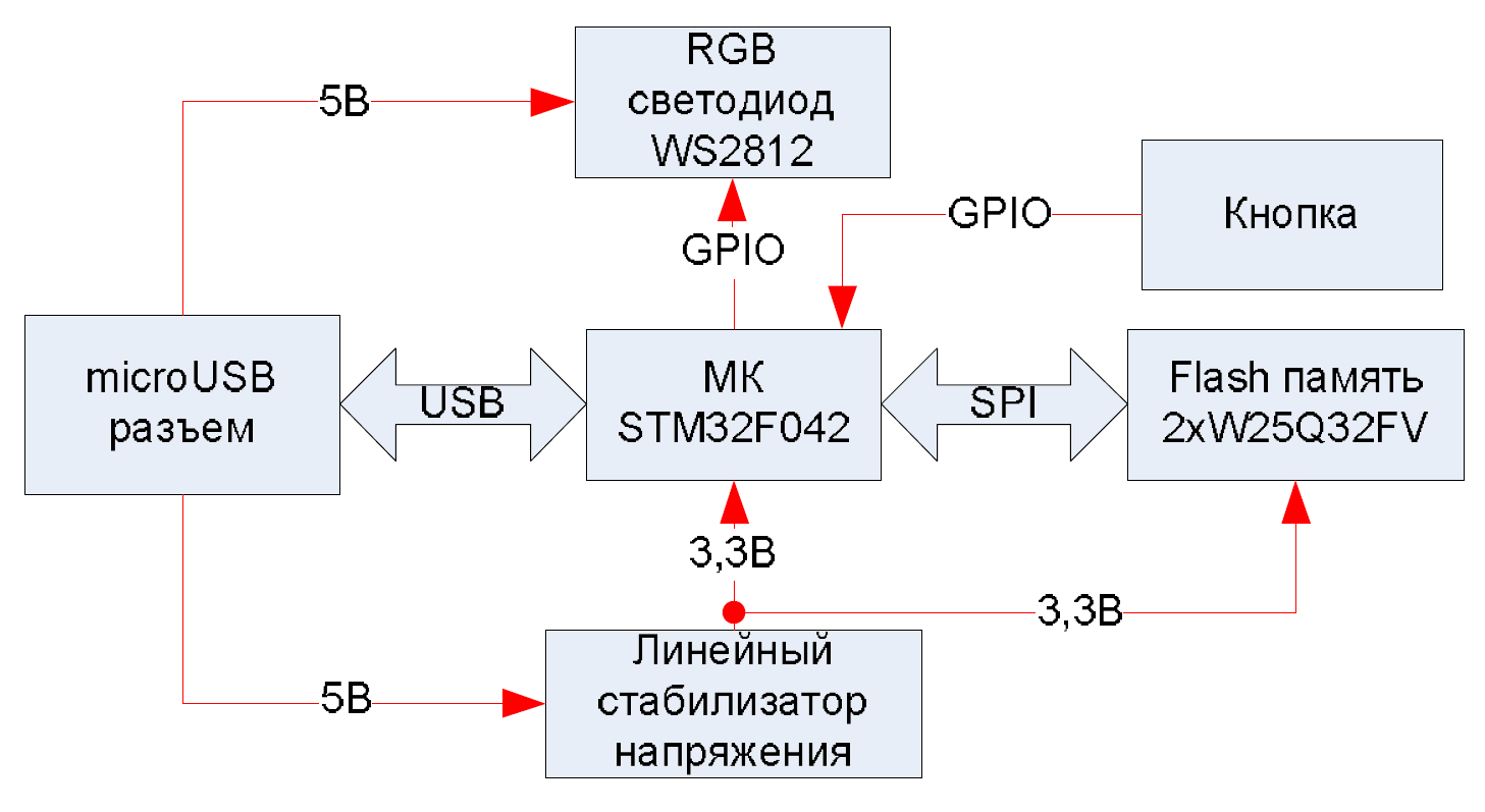
Details were taken from those that we had in stock, and also used more than once in devices. According to the scheme, the cheapest MK with USB on board STM32F042F6P6, simple LDO is XC6206P332MR, 32 Mbit SPI memory W25Q32FVSSIG (2 pcs on the board, but eventually soldered one), controlled by RGB LED WS2812.
Schematic diagram:

The minimum of details and the most important miscalculation is the hope that WS2812 will work normally at the level of 3.3V (Slavik! Yes, I did it a hundred times ... many said).
The board was made of the minimum width, in order to hide it as much as possible under the edge of the heart. White colour. The result in the figure.

Remember I mentioned the timid hope that WS2812 will work at 3.3V level? So there will not be !!! More precisely, everything seems to have worked before the USB exchange began. At the same time, the Blue channel began to fail. We were looking for a problem in the software for a long time, thinking that there was not enough processor resources, but then we pulled up the PB1 leg to 5V through a 1kΩ resistor and it all worked out clearly. The level of log.1 became approximately 4.3V. I understand that doing so is not good, but there was no choice. The board turned out pretty elegant "farm":

To facilitate the programming of the MK, it was decided to use the STM HAL Library, since almost everything is already there; you just need to add logic and connect all its modules together. In this, in part, STM32CubeMX helped us - the generation of most of the code can be assigned to it. But then everyone decides for himself - the generated code will still have to be significantly corrected, and you will have to pay the firmware size - the HAL library is not compact.
However, in our microcontroller 32kb is available, the firmware will take a little more than half, so it is logical to store three-byte sequences (RGB) in the remaining memory, which we transmit in turn to the input of the LED. Pressing the button will cycle through the sequences that are recorded in the MK flash.
Here we are confronted with the first problem: the WS2812 LED is very demanding on the period and duration of pulses, while the pulse time (0.4-0.8 μs) is sufficiently short for a processor operating at 48 MHz. In addition, we must note that in addition to controlling the LED, our microcontroller will also need to maintain communication with the PC via usb and read / write flash memory.
Fortunately, this diode is quite popular and several ways to implement its protocol are described on the Internet, including on STM microcontrollers. We have chosen, perhaps, one of the most difficult from the point of view of implementation, but also at the same time the most effective from the point of view of processor time - DMA + timer. DMA writes directly to the GPIO port, the timer controls the DMA channels. Since DMA writes to the entire port at once, then using other port pins will not work as an output. That is why the output of PB1 was chosen to control the LED. Ideologically, everything is simple, but it would have to be pretty tricky with the implementation if it were not for the wonderful library that Martin Hubáček wrote and posted on github . After a little dopilivaniya under our MK and the selected method of storing RGB sequences, we get a working LED.
Imagine giving you a heart with a personalized greeting. You come home, joyful, connect it to the computer, and instead of “I love!” It gives you “The necessary device driver was not found” or something else like that. Not good.
Therefore, the heart should be recognized as a flash drive in any of the common operating systems, without requiring the installation of drivers. Therefore, we will use the usb class called “Mass storage device”, the benefit of the STM32 USB Device Library provides us with a turnkey solution. Stop! Ready ???? Let's see.
We create a project in STM32CubeMX, combine read / write methods for spi flash memory with corresponding calls in the usb mass storage module and immediately find two problems: the flash drive does not want to be safely removed and “chokes” when trying to write something more than the text “Hello World "in the README.txt file.
The first problem is easy to solve - you need to implement the missing SCSI processing of the StartStopUnit command. The second is more difficult to solve. The file system block size (of course, having only 8mb of space, we will use Fat16) 512 bytes. Memory is able to erase only blocks of 4K. We will have to reserve one of the blocks for temporary storage (we cannot afford 4kb of RAM with 6kb available). That is, to write 512 bytes, you have to copy 4k, erase 4k, and copy them back. Moreover, if the file is large enough, the operating system wants to write to the drive 64kB at a time, and our controller is not able to serve such a large amount of data for it at the right time, given that the flash drive used is also not the fastest. In general, while the controller slowly writes data 256 bytes at a time (the size of the memory page), the operating system (at least Fedora, on which all this was tested) already has time to decide that the drive has died a brave death.
Connoisseurs will certainly indicate a more elegant solution to the problem, but "we will go another way." Reading the flash memory will be via the mass storage device interface and in this mode it will position itself as Read-Only (at the same time it will be possible to “pull the heart” out of the computer without any “safe extraction”, but fearing to spoil the file system), and we will record via virtual com port (aka Communication Device Class). Through the same interface, we will write our RGB sequences to the end of the MK memory.
Download mode (mass storage or cdc) will be selected when loading by the pressed (or not) button.
It is said - done (as always, the main amount of time and coffee was spent on these two words). Returning read-write to the MSC interface, because it turns out that in the read-only mode, macOs refuses to recognize the USB flash drive, it doesn’t matter, here we’re fooled by the operating system and will return “success” to any write request without doing anything (again, the decision from the category of "if not elegant, but cheap and cheerful"). Things are easy - PC software.
Since it was decided to make the setting and firmware via the cdc interface, it is no longer possible to drag the files with the mouse and you need a special application that will know how to do it. Its main task is to provide the user with the opportunity to create a disk image, add user files there and write this image into flash memory. Also, the application must provide an interface for creating / reading / writing RGB sequences.
The application should be cross-platform, and here the Qt library for creating a graphical interface and FatFS from ChaN for creating and managing the image of the disk come to our aid. Data exchange with the device through the com-port is available in Qt of the latest versions “out of the box” (QSerialPort module), for disk image operations we use QTreeView with the item model, inherited from QabstractItemModel, which additionally implements Drag & Drop operations (whatever you say, drag and drop mouse "convenient and familiar, if we are talking about files / folders). QListWidget (for displaying a sequence of colors), QtColorWidgets (by Mattia Basaglia) for color selection and QEasingCurve’s built-in Qt class for smooth (or, conversely, hopping) transitions between colors and creating a rainbow effect is useful for creating RGB sequences.
Result: the application has two tabs:
1) “Storage” for files

2) "LED" to control RGB sequences

Dialogue for creating RGB sequences:

The dialogue works in three modes:
a) RGB - allows you to specify transitions between two colors specified in the RGB notation.
b) HSV is the same, but in the HSV notation — the overflow is more familiar to the human eye, in particular, the “HSV” + “Iterate-> HUE” mode allows you to create a rainbow.
c) Custom - this mode allows you to manually set each color of a sequence. It’s not possible to make large sequences so that in this mode it is very convenient to put out the heart for a while (setting the color “black”) in this mode.
And finally, the definition of our device as a flash drive in Windows / macOs / Linux (Gnome):


And after all the work done and the text I wrote, I found that I did not take a single normal photo of the heart itself. Therefore, I attach the option "how it happened":


In reality, it looks great (especially with the presence of engraving). Love your loved ones !!!
Well, since: Not so expensive gift, how expensive attention (s) - try to invest time. I present to your attention "Heart v1.0"
The main idea of the device was collectively invented with my team for “Christmas Tree v1.0”. Briefly set of functions:
')
- engraved heart greeting
- powered by phone's memory (microUSB connector)
- RGB backlight with the ability to record flash profiles, switchable by button
- night light mode
- Built-in memory to record congratulations. When connected to a PC is defined as a flash drive.
Having discussed / rejoiced at the pledged functionality, we decided to do it - no one then suspected what time costs the heart would require ...
Iron
As it turned out - the simplest part of the heart. The first thing was drawn up a block diagram of the device:
Details were taken from those that we had in stock, and also used more than once in devices. According to the scheme, the cheapest MK with USB on board STM32F042F6P6, simple LDO is XC6206P332MR, 32 Mbit SPI memory W25Q32FVSSIG (2 pcs on the board, but eventually soldered one), controlled by RGB LED WS2812.
Schematic diagram:
The minimum of details and the most important miscalculation is the hope that WS2812 will work normally at the level of 3.3V (Slavik! Yes, I did it a hundred times ... many said).
The board was made of the minimum width, in order to hide it as much as possible under the edge of the heart. White colour. The result in the figure.
Feil
Remember I mentioned the timid hope that WS2812 will work at 3.3V level? So there will not be !!! More precisely, everything seems to have worked before the USB exchange began. At the same time, the Blue channel began to fail. We were looking for a problem in the software for a long time, thinking that there was not enough processor resources, but then we pulled up the PB1 leg to 5V through a 1kΩ resistor and it all worked out clearly. The level of log.1 became approximately 4.3V. I understand that doing so is not good, but there was no choice. The board turned out pretty elegant "farm":
Soft MK
To facilitate the programming of the MK, it was decided to use the STM HAL Library, since almost everything is already there; you just need to add logic and connect all its modules together. In this, in part, STM32CubeMX helped us - the generation of most of the code can be assigned to it. But then everyone decides for himself - the generated code will still have to be significantly corrected, and you will have to pay the firmware size - the HAL library is not compact.
However, in our microcontroller 32kb is available, the firmware will take a little more than half, so it is logical to store three-byte sequences (RGB) in the remaining memory, which we transmit in turn to the input of the LED. Pressing the button will cycle through the sequences that are recorded in the MK flash.
Here we are confronted with the first problem: the WS2812 LED is very demanding on the period and duration of pulses, while the pulse time (0.4-0.8 μs) is sufficiently short for a processor operating at 48 MHz. In addition, we must note that in addition to controlling the LED, our microcontroller will also need to maintain communication with the PC via usb and read / write flash memory.
Fortunately, this diode is quite popular and several ways to implement its protocol are described on the Internet, including on STM microcontrollers. We have chosen, perhaps, one of the most difficult from the point of view of implementation, but also at the same time the most effective from the point of view of processor time - DMA + timer. DMA writes directly to the GPIO port, the timer controls the DMA channels. Since DMA writes to the entire port at once, then using other port pins will not work as an output. That is why the output of PB1 was chosen to control the LED. Ideologically, everything is simple, but it would have to be pretty tricky with the implementation if it were not for the wonderful library that Martin Hubáček wrote and posted on github . After a little dopilivaniya under our MK and the selected method of storing RGB sequences, we get a working LED.
Flash memory
Imagine giving you a heart with a personalized greeting. You come home, joyful, connect it to the computer, and instead of “I love!” It gives you “The necessary device driver was not found” or something else like that. Not good.
Therefore, the heart should be recognized as a flash drive in any of the common operating systems, without requiring the installation of drivers. Therefore, we will use the usb class called “Mass storage device”, the benefit of the STM32 USB Device Library provides us with a turnkey solution. Stop! Ready ???? Let's see.
We create a project in STM32CubeMX, combine read / write methods for spi flash memory with corresponding calls in the usb mass storage module and immediately find two problems: the flash drive does not want to be safely removed and “chokes” when trying to write something more than the text “Hello World "in the README.txt file.
The first problem is easy to solve - you need to implement the missing SCSI processing of the StartStopUnit command. The second is more difficult to solve. The file system block size (of course, having only 8mb of space, we will use Fat16) 512 bytes. Memory is able to erase only blocks of 4K. We will have to reserve one of the blocks for temporary storage (we cannot afford 4kb of RAM with 6kb available). That is, to write 512 bytes, you have to copy 4k, erase 4k, and copy them back. Moreover, if the file is large enough, the operating system wants to write to the drive 64kB at a time, and our controller is not able to serve such a large amount of data for it at the right time, given that the flash drive used is also not the fastest. In general, while the controller slowly writes data 256 bytes at a time (the size of the memory page), the operating system (at least Fedora, on which all this was tested) already has time to decide that the drive has died a brave death.
Connoisseurs will certainly indicate a more elegant solution to the problem, but "we will go another way." Reading the flash memory will be via the mass storage device interface and in this mode it will position itself as Read-Only (at the same time it will be possible to “pull the heart” out of the computer without any “safe extraction”, but fearing to spoil the file system), and we will record via virtual com port (aka Communication Device Class). Through the same interface, we will write our RGB sequences to the end of the MK memory.
Download mode (mass storage or cdc) will be selected when loading by the pressed (or not) button.
It is said - done (as always, the main amount of time and coffee was spent on these two words). Returning read-write to the MSC interface, because it turns out that in the read-only mode, macOs refuses to recognize the USB flash drive, it doesn’t matter, here we’re fooled by the operating system and will return “success” to any write request without doing anything (again, the decision from the category of "if not elegant, but cheap and cheerful"). Things are easy - PC software.
PC software
Since it was decided to make the setting and firmware via the cdc interface, it is no longer possible to drag the files with the mouse and you need a special application that will know how to do it. Its main task is to provide the user with the opportunity to create a disk image, add user files there and write this image into flash memory. Also, the application must provide an interface for creating / reading / writing RGB sequences.
The application should be cross-platform, and here the Qt library for creating a graphical interface and FatFS from ChaN for creating and managing the image of the disk come to our aid. Data exchange with the device through the com-port is available in Qt of the latest versions “out of the box” (QSerialPort module), for disk image operations we use QTreeView with the item model, inherited from QabstractItemModel, which additionally implements Drag & Drop operations (whatever you say, drag and drop mouse "convenient and familiar, if we are talking about files / folders). QListWidget (for displaying a sequence of colors), QtColorWidgets (by Mattia Basaglia) for color selection and QEasingCurve’s built-in Qt class for smooth (or, conversely, hopping) transitions between colors and creating a rainbow effect is useful for creating RGB sequences.
Result: the application has two tabs:
1) “Storage” for files
2) "LED" to control RGB sequences
Dialogue for creating RGB sequences:
The dialogue works in three modes:
a) RGB - allows you to specify transitions between two colors specified in the RGB notation.
b) HSV is the same, but in the HSV notation — the overflow is more familiar to the human eye, in particular, the “HSV” + “Iterate-> HUE” mode allows you to create a rainbow.
c) Custom - this mode allows you to manually set each color of a sequence. It’s not possible to make large sequences so that in this mode it is very convenient to put out the heart for a while (setting the color “black”) in this mode.
And finally, the definition of our device as a flash drive in Windows / macOs / Linux (Gnome):
Conclusion
And after all the work done and the text I wrote, I found that I did not take a single normal photo of the heart itself. Therefore, I attach the option "how it happened":
In reality, it looks great (especially with the presence of engraving). Love your loved ones !!!
Source: https://habr.com/ru/post/401013/
All Articles