Light meter from the Chinese player
I am interested in growing plants and I wanted to know the level of illumination, since for plants there are recommended levels of illumination. On aliexpress, a calibrated BH1750 sensor was purchased. Also on the Internet there is information about the Chinese player, which allows you to collect something from it, as there is already a library for display. And I wanted to cross them: the display, the arduin, the sensor, and of course, all powered by the built-in battery in the player.
Actually this is what happened:
')
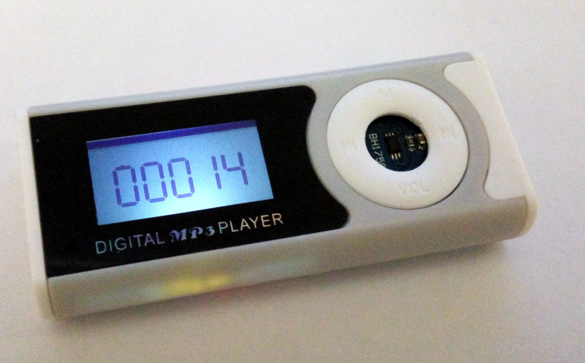
Compact light meter in the case of the player.
The characteristics of the luxmeter are determined by the sensor, and it can measure the illuminance from 1 to 65535 lux.
As you can see on the photo on the screen, there is nothing but numbers, not even units of measurement. I did not do it because I do not see the need for it, and the screen is small. There is no battery control.
I bought the player here . I bring the link because in this case there are at least 2 board options, and I bring contacts for my own.
There is a note on the player: since I left my own charging circuit, it was necessary to be careful with it: it easily recharges the battery and it swells. It’s better not to use it at all, ideally, to make your board a charge controller, a microcontroller, etc.
Assembly:
1. Player carefully disassemble, save all the details! They will still be useful to you.
2. Battery temporarily unsolder. Vypayat native controller, 3.5mm connector (for headphones), a connector for a memory card, a LED flashlight.
3. I need an Arduino Pro Mini, I only had 5V 16 MHz, but it works successfully from 3.3V. And of course you need a USB-UART 3.3V adapter.
4. Need a thin wire. I have MGTF, I don’t remember the diameter, but I’m thick for this task, I hardly put it in, take the thinnest one right away.
Since none of the available libraries for the display did not suit me, I wrote my code, including the management of the display based on one of them. The code is broken down by file, compiled in Arduino IDE 1.6.12.
I want to say right away that it’s rather an indicator than a measuring device, but it’s useful to have such an indicator, and it will take one evening to assemble if you have some experience.
There is also a video, but without sound. I wanted to record it separately, but it turned out that none of my mic could do it normally.
Actually this is what happened:
')
Compact light meter in the case of the player.
The characteristics of the luxmeter are determined by the sensor, and it can measure the illuminance from 1 to 65535 lux.
As you can see on the photo on the screen, there is nothing but numbers, not even units of measurement. I did not do it because I do not see the need for it, and the screen is small. There is no battery control.
I bought the player here . I bring the link because in this case there are at least 2 board options, and I bring contacts for my own.
There is a note on the player: since I left my own charging circuit, it was necessary to be careful with it: it easily recharges the battery and it swells. It’s better not to use it at all, ideally, to make your board a charge controller, a microcontroller, etc.
Assembly:
1. Player carefully disassemble, save all the details! They will still be useful to you.
2. Battery temporarily unsolder. Vypayat native controller, 3.5mm connector (for headphones), a connector for a memory card, a LED flashlight.
3. I need an Arduino Pro Mini, I only had 5V 16 MHz, but it works successfully from 3.3V. And of course you need a USB-UART 3.3V adapter.
4. Need a thin wire. I have MGTF, I don’t remember the diameter, but I’m thick for this task, I hardly put it in, take the thinnest one right away.
I did not make the scheme, the necessary contacts are shown in the pictures:


Since none of the available libraries for the display did not suit me, I wrote my code, including the management of the display based on one of them. The code is broken down by file, compiled in Arduino IDE 1.6.12.
Luxmeter_mod2.ino
#include <avr/pgmspace.h> #define pgm pgm_read_byte #include <Wire.h> #include <BH1750.h> BH1750 lightMeter; unsigned int lux; #define CS 10 #define Data 11 #define Clock 13 #define DC A0 #define LCD_X 128 #define LCD_Y 64 #define LCD_String 8 #define swap(a, b) { int t = a; a = b; b = t; } #define LCD_D 1 #define LCD_C 0 byte LCD_RAM[LCD_X*LCD_String]; #define BLACK 1 #define WHITE 0 #define LCDWIDTH 128 #define LCDHEIGHT 64 #define CMD_DISPLAY_OFF 0xAE #define CMD_DISPLAY_ON 0xAF #define CMD_SET_DISP_START_LINE 0x40 #define CMD_SET_PAGE 0xB0 #define CMD_SET_COLUMN_UPPER 0x10 #define CMD_SET_COLUMN_LOWER 0x00 #define CMD_SET_ADC_NORMAL 0xA0 #define CMD_SET_ADC_REVERSE 0xA1 #define CMD_SET_DISP_NORMAL 0xA6 #define CMD_SET_DISP_REVERSE 0xA7 #define CMD_SET_ALLPTS_NORMAL 0xA4 #define CMD_SET_ALLPTS_ON 0xA5 #define CMD_SET_BIAS_9 0xA2 #define CMD_SET_BIAS_7 0xA3 #define CMD_RMW 0xE0 #define CMD_RMW_CLEAR 0xEE #define CMD_INTERNAL_RESET 0xE2 #define CMD_SET_COM_NORMAL 0xC0 #define CMD_SET_COM_REVERSE 0xC8 #define CMD_SET_POWER_CONTROL 0x28 #define CMD_SET_RESISTOR_RATIO 0x20 #define CMD_SET_VOLUME_FIRST 0x81 #define CMD_SET_VOLUME_SECOND 0 #define CMD_SET_STATIC_OFF 0xAC #define CMD_SET_STATIC_ON 0xAD #define CMD_SET_STATIC_REG 0x0 #define CMD_SET_BOOSTER_FIRST 0xF8 #define CMD_SET_BOOSTER_234 0 #define CMD_SET_BOOSTER_5 1 #define CMD_SET_BOOSTER_6 3 #define CMD_NOP 0xE3 #define CMD_TEST Font.ino
#include <avr/pgmspace.h> // 1632 static const char mass16x32 [10][64] PROGMEM ={ { 0xF8, 0xFC, 0xFA, 0x07, 0x07, 0x07, 0x07, 0x07, 0x07, 0x07, 0x07, 0x07, 0x07, 0xFA, 0xFC, 0xF8, //0 0x3F, 0x7F, 0x3F, 0x00, 0x00, 0x00, 0x00, 0x00, 0x00, 0x00, 0x00, 0x00, 0x00, 0x3F, 0x7F, 0x3F, 0xFE, 0xFF, 0xFE, 0x00, 0x00, 0x00, 0x00, 0x00, 0x00, 0x00, 0x00, 0x00, 0x00, 0xFE, 0xFF, 0xFE, 0x1F, 0x3F, 0x5F, 0xE0, 0xE0, 0xE0, 0xE0, 0xE0, 0xE0, 0xE0, 0xE0, 0xE0, 0xE0, 0x5F, 0x3F, 0x1F}, { 0x00, 0x00, 0x00, 0x00, 0x00, 0x00, 0x00, 0x00, 0x00, 0x00, 0x00, 0x00, 0x00, 0xF8, 0xFC, 0xF8, //1 0x00, 0x00, 0x00, 0x00, 0x00, 0x00, 0x00, 0x00, 0x00, 0x00, 0x00, 0x00, 0x00, 0x3F, 0x7F, 0x3F, 0x00, 0x00, 0x00, 0x00, 0x00, 0x00, 0x00, 0x00, 0x00, 0x00, 0x00, 0x00, 0x00, 0xFE, 0xFF, 0xFE, 0x00, 0x00, 0x00, 0x00, 0x00, 0x00, 0x00, 0x00, 0x00, 0x00, 0x00, 0x00, 0x00, 0x1F, 0x3F, 0x1F}, {0x00, 0x00, 0x02, 0x07, 0x07, 0x07, 0x07, 0x07, 0x07, 0x07, 0x07, 0x07, 0x07, 0xFA, 0xFC, 0xF8, //2 0x00, 0x00, 0x80, 0xC0, 0xC0, 0xC0, 0xC0, 0xC0, 0xC0, 0xC0, 0xC0, 0xC0, 0xC0, 0xBF, 0x7F, 0x3F, 0xFE, 0xFF, 0xFE, 0x01, 0x01, 0x01, 0x01, 0x01, 0x01, 0x01, 0x01, 0x01, 0x01, 0x00, 0x00, 0x00, 0x1F, 0x3F, 0x5F, 0xE0, 0xE0, 0xE0, 0xE0, 0xE0, 0xE0, 0xE0, 0xE0, 0xE0, 0xE0, 0x40, 0x00, 0x00}, {0x00, 0x00, 0x02, 0x07, 0x07, 0x07, 0x07, 0x07, 0x07, 0x07, 0x07, 0x07, 0x07, 0xFA, 0xFC, 0xF8, //3 0x00, 0x00, 0x80, 0xC0, 0xC0, 0xC0, 0xC0, 0xC0, 0xC0, 0xC0, 0xC0, 0xC0, 0xC0, 0xBF, 0x7F, 0x3F, 0x00, 0x00, 0x00, 0x01, 0x01, 0x01, 0x01, 0x01, 0x01, 0x01, 0x01, 0x01, 0x01, 0xFE, 0xFF, 0xFE, 0x00, 0x00, 0x40, 0xE0, 0xE0, 0xE0, 0xE0, 0xE0, 0xE0, 0xE0, 0xE0, 0xE0, 0xE0, 0x5F, 0x3F, 0x1F}, {0xF8, 0xFC, 0xF8, 0x00, 0x00, 0x00, 0x00, 0x00, 0x00, 0x00, 0x00, 0x00, 0x00, 0xF8, 0xFC, 0xF8, //4 0x3F, 0x7F, 0xBF, 0xC0, 0xC0, 0xC0, 0xC0, 0xC0, 0xC0, 0xC0, 0xC0, 0xC0, 0xC0, 0xBF, 0x7F, 0x3F, 0x00, 0x00, 0x00, 0x01, 0x01, 0x01, 0x01, 0x01, 0x01, 0x01, 0x01, 0x01, 0x01, 0xFE, 0xFF, 0xFE, 0x00, 0x00, 0x00, 0x00, 0x00, 0x00, 0x00, 0x00, 0x00, 0x00, 0x00, 0x00, 0x00, 0x1F, 0x3F, 0x1F}, {0xF8, 0xFC, 0xFA, 0x07, 0x07, 0x07, 0x07, 0x07, 0x07, 0x07, 0x07, 0x07, 0x07, 0x02, 0x00, 0x00, //5 0x3F, 0x7F, 0xBF, 0xC0, 0xC0, 0xC0, 0xC0, 0xC0, 0xC0, 0xC0, 0xC0, 0xC0, 0xC0, 0x80, 0x00, 0x00, 0x00, 0x00, 0x00, 0x01, 0x01, 0x01, 0x01, 0x01, 0x01, 0x01, 0x01, 0x01, 0x01, 0xFE, 0xFF, 0xFE, 0x00, 0x00, 0x40, 0xE0, 0xE0, 0xE0, 0xE0, 0xE0, 0xE0, 0xE0, 0xE0, 0xE0, 0xE0, 0x5F, 0x3F, 0x1F}, {0xF8, 0xFC, 0xFA, 0x07, 0x07, 0x07, 0x07, 0x07, 0x07, 0x07, 0x07, 0x07, 0x07, 0x02, 0x00, 0x00, //6 0x3F, 0x7F, 0xBF, 0xC0, 0xC0, 0xC0, 0xC0, 0xC0, 0xC0, 0xC0, 0xC0, 0xC0, 0xC0, 0x80, 0x00, 0x00, 0xFE, 0xFF, 0xFE, 0x01, 0x01, 0x01, 0x01, 0x01, 0x01, 0x01, 0x01, 0x01, 0x01, 0xFE, 0xFF, 0xFE, 0x1F, 0x3F, 0x5F, 0xE0, 0xE0, 0xE0, 0xE0, 0xE0, 0xE0, 0xE0, 0xE0, 0xE0, 0xE0, 0x5F, 0x3F, 0x1F}, {0x00, 0x00, 0x02, 0x07, 0x07, 0x07, 0x07, 0x07, 0x07, 0x07, 0x07, 0x07, 0x07, 0xFA, 0xFC, 0xF8, //7 0x00, 0x00, 0x00, 0x00, 0x00, 0x00, 0x00, 0x00, 0x00, 0x00, 0x00, 0x00, 0x00, 0x3F, 0x7F, 0x3F, 0x00, 0x00, 0x00, 0x00, 0x00, 0x00, 0x00, 0x00, 0x00, 0x00, 0x00, 0x00, 0x00, 0xFE, 0xFF, 0xFE, 0x00, 0x00, 0x00, 0x00, 0x00, 0x00, 0x00, 0x00, 0x00, 0x00, 0x00, 0x00, 0x00, 0x1F, 0x3F, 0x1F}, {0xF8, 0xFC, 0xFA, 0x07, 0x07, 0x07, 0x07, 0x07, 0x07, 0x07, 0x07, 0x07, 0x07, 0xFA, 0xFC, 0xF8, //8 0x3F, 0x7F, 0xBF, 0xC0, 0xC0, 0xC0, 0xC0, 0xC0, 0xC0, 0xC0, 0xC0, 0xC0, 0xC0, 0xBF, 0x7F, 0x3F, 0xFE, 0xFF, 0xFE, 0x01, 0x01, 0x01, 0x01, 0x01, 0x01, 0x01, 0x01, 0x01, 0x01, 0xFE, 0xFF, 0xFE, 0x1F, 0x3F, 0x5F, 0xE0, 0xE0, 0xE0, 0xE0, 0xE0, 0xE0, 0xE0, 0xE0, 0xE0, 0xE0, 0x5F, 0x3F, 0x1F}, {0xF8, 0xFC, 0xFA, 0x07, 0x07, 0x07, 0x07, 0x07, 0x07, 0x07, 0x07, 0x07, 0x07, 0xFA, 0xFC, 0xF8, //9 0x3F, 0x7F, 0xBF, 0xC0, 0xC0, 0xC0, 0xC0, 0xC0, 0xC0, 0xC0, 0xC0, 0xC0, 0xC0, 0xBF, 0x7F, 0x3F, 0x00, 0x00, 0x00, 0x01, 0x01, 0x01, 0x01, 0x01, 0x01, 0x01, 0x01, 0x01, 0x01, 0xFE, 0xFF, 0xFE, 0x00, 0x00, 0x40, 0xE0, 0xE0, 0xE0, 0xE0, 0xE0, 0xE0, 0xE0, 0xE0, 0xE0, 0xE0, 0x5F, 0x3F, 0x1F}}; <source lang="arduino"> LCD.ino
#include <avr/pgmspace.h> //====================================================== void Clear_LCD() { for (int index = 0; index < 864 ; index++) { LCD_RAM[index] = (0x00); } } //======================================================= void dWrite(byte pin, byte val) { byte bit = digitalPinToBitMask(pin); volatile byte *out; out = portOutputRegister(digitalPinToPort(pin)); (val) ? *out |= bit : *out &= ~bit; } #define _BV(bit) (1<<(bit)) //========================================================= 8 void SendByte(byte mode, byte c) { dWrite(CS, 0); (mode) ? dWrite(DC, 1) : dWrite(DC, 0); for (byte i = 0; i <8; i++) { dWrite(Clock, 0); (c & 0x80) ? dWrite(Data, 1) : dWrite(Data, 0); dWrite(Clock, 1); c <<= 1; } } //===================================================== void Update() { for (byte p = 0; p < 8; p++) { //SendByte(LCD_C, CMD_SET_PAGE | pagemap[p]); SendByte(LCD_C, CMD_SET_PAGE | p); byte col = 0; SendByte(LCD_C, CMD_SET_COLUMN_LOWER | (1 & 0xf)); SendByte(LCD_C, CMD_SET_COLUMN_UPPER | ((1 >> 4) & 0x0F)); SendByte(LCD_C, CMD_RMW); for (byte col = 0; col < LCD_X; col++) { SendByte(LCD_D, LCD_RAM[(LCD_X * p) + col]); } } } //=================================================== void drawPixel (byte x, byte y, boolean color) { if ((x < 0) || (x >= LCD_X) || (y < 0) || (y >= LCD_Y)) return; if (color) LCD_RAM[x + (y / 8)*LCD_X] |= _BV(y % 8); else LCD_RAM[x + (y / 8)*LCD_X] &= ~_BV(y % 8); } //====================================================== void drawBitmap(byte x, byte y, const char *bitmap, byte w, byte h, boolean color) { for (int16_t j = 0; j < h; j++) { for (int16_t i = 0; i < w; i++ ) { if (pgm(bitmap + i + (j / 8)*w) & _BV(j % 8)) { drawPixel(x + i, y + j, color); } } } } //======================================================================== // //======================================================================== //=================================================== void Inicialize() { pinMode(CS, OUTPUT); pinMode(Data, OUTPUT); pinMode(Clock, OUTPUT); pinMode(DC, OUTPUT); // dWrite(CS, 0); delay(500); SendByte(LCD_C, CMD_SET_BIAS_7); // LCD bias select SendByte(LCD_C, CMD_SET_ADC_NORMAL); // ADC select SendByte(LCD_C, CMD_SET_COM_REVERSE); // SHL select SendByte(LCD_C, CMD_SET_DISP_START_LINE); // Initial display line SendByte(LCD_C, CMD_SET_POWER_CONTROL | 0x4); // turn on voltage converter (VC=1, VR=0, VF=0) delay(50); SendByte(LCD_C, CMD_SET_POWER_CONTROL | 0x6); // turn on voltage regulator (VC=1, VR=1, VF=0) delay(50); SendByte(LCD_C, CMD_SET_POWER_CONTROL | 0x7); // turn on voltage follower (VC=1, VR=1, VF=1) delay(10); SendByte(LCD_C, CMD_SET_RESISTOR_RATIO | 0x6); // set lcd operating voltage (regulator resistor, ref voltage resistor) SendByte(LCD_C, CMD_DISPLAY_ON); SendByte(LCD_C, CMD_SET_ALLPTS_NORMAL); SendByte(LCD_C, CMD_SET_DISP_REVERSE); SendByte(LCD_C, CMD_SET_VOLUME_FIRST); SendByte(LCD_C, CMD_SET_VOLUME_SECOND | (0 & 0x3f)); Clear_LCD(); Update(); } //========================= 1632 XY void simb16x32(byte x, byte y, boolean color, byte c) { for (byte k = 0; k < 4; k++) { for (byte i = 0; i < 16; i++) { byte line = pgm(&(mass16x32[c][i + k * 16])); for (byte j = 0; j < 8; j++) { (line & 0x01) ? drawPixel(x + i, y + j + k * 8, color) : drawPixel(x + i, y + j + k * 8, !color); line >>= 1; } } } } <source lang="arduino"> Main.ino
#include <avr/pgmspace.h> void setup(){ Inicialize(); lightMeter.begin(); } + void loop(){ lux = lightMeter.readLightLevel(); simb16x32(95, 17, 1, lux%10); lux/=10; simb16x32(75, 17, 1, lux%10); lux/=10; simb16x32(55, 17, 1, lux%10); lux/=10; simb16x32(35, 17, 1, lux%10); lux/=10; simb16x32(15, 17, 1, lux%10); Update(); delay(300); } <source lang="arduino"> I want to say right away that it’s rather an indicator than a measuring device, but it’s useful to have such an indicator, and it will take one evening to assemble if you have some experience.
There is also a video, but without sound. I wanted to record it separately, but it turned out that none of my mic could do it normally.
Source: https://habr.com/ru/post/400989/
All Articles