Connecting controlled power supplies, sensors and relays to server motherboards. Without arduino
Connection of various sensors, sensors, relays, GPIO expanders and other “Arduinov” facilities via the I²C bus directly to the server motherboards via the on-board controller (BMC) IPMI interface. Practical examples of I²C devices and working with them from the command line with the ipmitool utility. SMBus, PMBus and power supply management. Not very documented limitations and security issues. Exposing proprietary .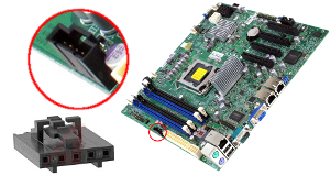 After installing the server into a self-made design, sometimes you want to connect something else to it: for example, temperature, pressure, humidity sensors, LCD screens or even PWM drivers of motors. There are buggy external devices that have to be remotely and hard reset using a relay, not levels, while the entire server as a whole. Or maybe the reader just wanted a GPIO comb with a LED garland? If this is not a single-type Raspberry Pi, but a full-sized server, you have to hang the microcontroller and mess with it: write firmware, test, build a host with the host, etc. Sometimes this is interesting in itself, but sometimes it happens the other way around: rather, write scripts and launch scripts, finally, just to work.
Unusual connectors on the gland always caused the author mixed feelings of engineering itch and fan fetishism. About these entertaining connectors here and speech.
DISCLAIMER
If you are reading this article somewhere outside the portal Geektimes, I recommend in a week or two to look at an authentic link . The fact is that the most interesting comments of readers will appear there (i.e., here) in the sidebars, I'm not talking about the elimination of shortcomings and blunders. It happens that an angry article angry residents of the club literally tear to shreds, simultaneously sending the author to the karmic abyss. In other words, if the authentic link does not open, then it is not necessary and read further this place.
The author conveys his greetings to the Far East (directly from the sky over the North Atlantic), and also apologizes to the respected trademarks: they do not need advertising so much that I make them funny names. Thus, the article is applicable to Super Miron products, but the author has little doubt about the availability of similar mechanisms on Harlampy-Pankrat products, Ivan Bralya Maryu, Iltan, Dolyan and others: entertaining connectors can most often be found on power supplies and disk baskets. At the same time try to expose and vaunted Kobzar Link.
')
Dear experts on server platforms, IPMI, I²C, SMBus and PMBus, correct, if something goes wrong. Usually, the author expresses his gratitude to creative readers with karmic points, but apologizes to those residents of the club, whom the gratitude has already been written out earlier, just the UFO does not order to do it twice. I wish you a pleasant reading.
From what was
The author is not ashamed to buy second-hand server motherboards for a penny and give them a second life. The old, noisy server mechanics (with power supplies) are sent to the scrap and replaced with new products, although of consumer class, but high-quality and quiet. But even from the vintage Super Miron X8 and X9 series, you can still get some awesome NAS for small businesses that combine enterpise functions, a file “time machine” against Trojan ransomware and network replication ...
Yellow program mockery
And after the discovery of signs of virtualization in FreeNAS, the author pushed the Windows machine there, with a yellow program and a whole bunch of USB hardware keys. Outside nothing sticks out, and 1C users work through ordinary web browsers, unaware of anything. Why not Linux? Because of the drivers of the CMC, of course. However, the IT combine and mockery of 1C is a separate story (I hope, soon). One USB pass through
jail and VirtualBox puff pastry is worth something ...Generally, about 20 years ago, for collective farms , the craftsmen used a parallel port for the printer as a GPIO, but now try to find it. The world has changed, as for me - for the better :)
Visual inspection
I already have almost a fossil, but quite a working product X9SCM-F (Intel C204 Express), plus his younger brother X9SCL-F (C202) has been working on a nearby object for a couple of years. If you rotate the product, as in the documentation, with the 24-pin ATX power connector to the north, the SATA ports will be somewhere in the Khabarovsk region. Further east, like Petropavlovsk-Kamchatsky, there is a pair of T-SGPIO 1 and 2 connectors, attracting the attention with the combination of letters "GPIO". The author led to this combination, but the reflexes of the geologist-researcher of fossil electronics turned out to be false. In fact, the key word here is SGPIO , it is a duplex signal bus with time division, using frames of constant length. The bus in turn passes three bits for each SATA port: to the HBA, the state of the basket, and to the basket, the state of the drives (active, failed, locator). This is an outdated technology; modern baskets use I²C. I didn’t dig very deeply, but it looks like the 6 onboard SATA ports were divided into groups of two northern and four southern, and each group hung its comb T-SGPIO. It is cumbersome, awkwardly, but also useless for collective farms . Go ahead, there is a small JWF1 connector in the Yuzhno-Sakhalinsk region, but this is just 5V power for the SATA DOM drive, which I don’t have. In the Far East, nothing more to do. Along the southern borders there is a whole ridge of paired 9-pin USB connectors and a second RS232 port, everything is clear with them. In the Northwest of COM2, a pair of JI2C1 / JI2C2 jumpers were discovered, opening up access to PCIe devices. This toolkit has remained a mystery for me, but I am almost sure that in fact JI2C1 / JI2C2 are SCL and SDA live outputs, simply separated from the 3.3V power supply and the “ground”, which are already in PCIe. Leave bye. JTPM connector painfully tricky, this is an extreme case. And from the front panel connector JF1, you can only squeeze out the UID LED by connecting it to the optorele. By the way, this is m. even conveniently: the limiting resistor is already built into the circuit, turned on the UID LED - opened (closed) the relay. For remote reset external device , perhaps, enough. The main thing is that the operator, having entered the BMC web interface a year later, did not turn on the UID LED just like that, at the same time dropping the external device . Okay, back to the extreme
I must say that the documentation about JPI2C is quite optimistic. It means that this is the output of the I²C bus for monitoring the health of the “native” power supply. Physically, JPI2C is a 5-pin Molex SL-type connector with a 0.1 ”(2.54mm) pitch and a key for protection against confused polarity, presumably catalog number 70543-0004. The response part (in the picture on the left below) is Molex 70066-0179 crimped Crimper (aka
Power Supply I²C Connector
Power Supply I²C Connector, located at JPI2C, monitors for power supply, fan and system temperature. See the table for the pin definitions.
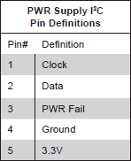
The empty JPI2C connector frankly teased with standard I²C bus contacts: SCL, SDA, GND and VCC. In the middle is a power failure alarm. Looking ahead, I venture to suggest that this Power Fail is the only way to raise an alarm on an external event without using an external microcontroller. Then we found the article FAQ ID 9492 of March 30, 2010, clearly hinting at the possibility of polling the I²C bus directly from the command line. Since BMC is clearly involved in monitoring the health of the power supply, and the
ipmitool team ipmitool clearly able to “talk” to the power supply units on the I²C bus, nothing should interfere with connecting something more to the JPI2C.Which connector: BL or BLS?
If a dear reader assembled a PC in the pre-MP3 era, he probably used 4-pin wiring to connect a CD drive with a sound card. I remember how these wiring were crowned with a simple BLS-4 type connector, as a result of which, in about half of the cases, CD drives did not play music even with the wiring , simply because of the reversed polarity. Then, finally, in the region, supplies of normal wiring with a polar connector of the type BL-04F were adjusted, so that only a very stupid and strong PC assembler could make a mistake. But MP3 was already sweeping through the market, and native audio discs gradually left our digital life ...
What am I for? The fact that the JPI2C connector on the Super Miron boards looks just like the audio connector on the old CD drive only has 5 pins instead of 4. The JPI2C will have a simple single
Universal loop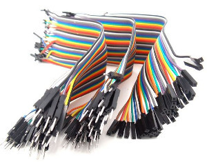 Beginners for prototyping recommend color “dial-up” 40-pin cable, which, if necessary, can be pulled into narrower components. The train of the desired width comes off easily, like quality toilet paper, i.e. strictly perforations. Available with different lengths and contacts type
 BLS-1 MF, MM or FF. Search on aliexpress: “dupont cable”.
Beginners for prototyping recommend color “dial-up” 40-pin cable, which, if necessary, can be pulled into narrower components. The train of the desired width comes off easily, like quality toilet paper, i.e. strictly perforations. Available with different lengths and contacts type Working with I²C devices from the command line
I connected to the JPI2C bought once on aliexpress the BMP180 sensor. Nothing came out at first. The addressing as a whole, and the
bus argument, choosing one bus, is not clear from how many caused bewilderment. But then I just made a script for busting (scanning) tires and compared the result of its work before connecting BMP180 and after. With the X9SCM-F board, the sensor immediately showed up on bus No. 3 at addresses 0xee and 0xef (see comment below). It will be necessary to rearrange JI2C1 / JI2C2 to the ENABLE position and see if suddenly PCIe cards will also respond ...ipmiscan.sh
This primitive piece of code is specially devoid of embellishment, gives something like a progress bar and assumes that the system has four buses (0, 1, 2 and 3). Requires bash 3.0+.
#!/bin/bash for bus in 0 1 2 3; do echo Bus $bus for i in {16..238..2}; do printf -v args "i2c bus=%d 0x%02x 0x01" $bus $i printf " 0x%02x" $i ipmitool $args 2>/dev/null && echo "(bus $bus)" done echo done The script enumerates only even addresses and does not touch the reserved ones . In I²C, the lowest bit is a read / write sign: each device occupies two addresses (read odd, write - even). The article FAQ ID 9492 confuses me because it only polls the even ones. But in the case of
ipmitool reading or writing is not determined by the address, but by the context of the command, right? The heavy IPMI 2.0 specification put everything in its place: the lower bit of the address in the Master Read-Write 0x06 0x52 ( 0x06 0x52 ) is generally reserved and must be cleared (equal to zero).The BMP180 sensor connected to JPI2C on the X9SCM-F board responded by (bus = 3) to the address
0xee (and 0xef , although this is the same). Those. the logical address of the device turned out to be 0x77 , as it should be according to the datasheet (Bosch grabbed off the top 8-bit address). My initial mistake was to look for BMP180 on the “raw” IPMI address 0x77 , this is wrong, for IPMI you just have to multiply the logical I²C address by two (shift one bit to the left). When working with I²C, this is, by the way, the most common mistake.The I²C tire hanging just like that is uninteresting neither in the air, nor even in a spherical vacuum. The well-known platform, upon request of the i2c sensor, will offer the respected reader a wide range of sensors already tied to mini-boards. Usually, it remains only to solder the contact comb; for this, a desire and a 30W soldering iron with solder and flux are sufficient; skills are not required. To test the theory, I decided to measure the temperature with a BMP180 sensor, but this turned out to be somewhat more complicated than I thought: the sensor is an example of a complex stateful device, and it would be more correct to say “extract temperature and pressure readings from a precision meter taking into account calibration factors”. But first, still give credit to a respected vendor.
Telemetry power supplies
At once I will make a reservation that this task is m. interesting, for example, for profiling the actual capacity of servers in the operation of data centers: if a group of servers is connected to one distributor, then figure out how much servers A and B consume without taking into account C and D, even if there is a tricked UPS that supplies the rack. All of this is proposed to find out via IPMI, receiving instantaneous values from selected servers directly over the network. For DIY, in addition to selecting the UPS and building the cooling system with feedback, nothing personally comes to my mind.
User Andrew Grekhov dealt with the Super Miron vendor’s power supplies, removing voltages, currents and temperatures from them. It is very interesting, although it is noticeable that the readings of the ADCs obviously have to be corrected for some calibration constants. I want to note that if you have a kernel interface, the
We give tribute to the user Andrew Grekhov , bravely rushed into an unequal battle with a complex and undocumented (as he thought) device. Fortunately, he did not forget to mention PMBus, which led me to the official website and acc. specifications. After all, PMBus is a specialized add-on over SMBus for managing power systems, and SMBus itself, in turn, is a development of I²C. It can be assumed that most modern managed power supplies use one or another PMBus specification. Because looking at all the existing PMBus frills and ready-made chips , a simple question arises: what's the point of reinventing the wheel? But I repeat, this is my guess.
So, digging a little deeper, you can find a description of the commands (registers) used by the controlled power supply units, for example, according to PMBus rev 1.1 . If the link does not open, go to www.pmbus.org , open the section with the old specifications and find PMBus Specification Part II Rev. 1.1. This is a command description document, see Table 26 in the APPENDIX I. Command Summary. Pay attention, for example, to the command registers 0x78 (STATUS_BYTE), 0x88 (READ_VIN), 0x89 (READ_IIN), 0x95 (READ_FREQUENCY) and others: they coincide exactly with the results of reverse engineering published on the forum at the link above. Returning to table 26, on the right is given the register width (Read Byte or Read Word) with the number of bytes read. Just in case, what if the reader forgot the difference between byte and word?
But the question remains: is it possible to read the calibration coefficients using the command 0x30 (COEFFICIENTS) using the SMBus standard packet operation using I²C? This is needed to convert spherically-vacuum registers to real volts, amps, etc. If I understand everything correctly, then from the point of view of the SMBus bus, you need to send a packet with the 0x30 command and byte count 2, the packet body is two bytes with the register code of interest (0x88 for READ_VIN) and a direction sign, which must be equal to one for reading. In response, the device should produce a packet of 1 + 5 + 1 bytes with the parameters m , B, and R , which are used to convert to physical volts. The first byte is the length, the last is PEC (if used). Those. The intrigue is whether it is possible to transmit a simple SMBus packet over I²C, for example, in this way:
I’m trying to send a packet
User Andrew Grekhov dealt with the Super Miron vendor’s power supplies, removing voltages, currents and temperatures from them. It is very interesting, although it is noticeable that the readings of the ADCs obviously have to be corrected for some calibration constants. I want to note that if you have a kernel interface, the
ipmitool command can be run on the host itself, without the -H, -U and -P parameters, and instead of raw 0x06 0x52 0x07 i2c bus=3 We give tribute to the user Andrew Grekhov , bravely rushed into an unequal battle with a complex and undocumented (as he thought) device. Fortunately, he did not forget to mention PMBus, which led me to the official website and acc. specifications. After all, PMBus is a specialized add-on over SMBus for managing power systems, and SMBus itself, in turn, is a development of I²C. It can be assumed that most modern managed power supplies use one or another PMBus specification. Because looking at all the existing PMBus frills and ready-made chips , a simple question arises: what's the point of reinventing the wheel? But I repeat, this is my guess.
So, digging a little deeper, you can find a description of the commands (registers) used by the controlled power supply units, for example, according to PMBus rev 1.1 . If the link does not open, go to www.pmbus.org , open the section with the old specifications and find PMBus Specification Part II Rev. 1.1. This is a command description document, see Table 26 in the APPENDIX I. Command Summary. Pay attention, for example, to the command registers 0x78 (STATUS_BYTE), 0x88 (READ_VIN), 0x89 (READ_IIN), 0x95 (READ_FREQUENCY) and others: they coincide exactly with the results of reverse engineering published on the forum at the link above. Returning to table 26, on the right is given the register width (Read Byte or Read Word) with the number of bytes read. Just in case, what if the reader forgot the difference between byte and word?
But the question remains: is it possible to read the calibration coefficients using the command 0x30 (COEFFICIENTS) using the SMBus standard packet operation using I²C? This is needed to convert spherically-vacuum registers to real volts, amps, etc. If I understand everything correctly, then from the point of view of the SMBus bus, you need to send a packet with the 0x30 command and byte count 2, the packet body is two bytes with the register code of interest (0x88 for READ_VIN) and a direction sign, which must be equal to one for reading. In response, the device should produce a packet of 1 + 5 + 1 bytes with the parameters m , B, and R , which are used to convert to physical volts. The first byte is the length, the last is PEC (if used). Those. The intrigue is whether it is possible to transmit a simple SMBus packet over I²C, for example, in this way:
ipmitool i2c bus=3 0x70 0x07 0x30 0x02 0x88 0x01 I’m trying to send a packet
0x30 0x02 0x88 0x01 0x70 , sitting on bus number 3, and then receive 7 bytes from the device (one byte with the packet length, five bytes of coefficients, one byte of PEC). The power supply address needs to be replaced with the actual one (the first can be 0x78 , followed by the backup units), and instead of 7 bytes, you can try to read 6 (without PEC). If someone has a Super Miron power supply, try, just not in production, because I can’t vouch for the consequences :) If all the assumptions are correct, you can get a very detailed picture directly from the power supply, the parameters are just dark.Temperature measurement by BMP180 sensor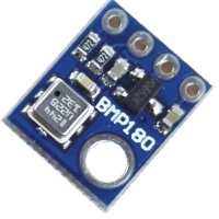 The BMP180 sensor measures pressure and temperature. It reads through double-byte register pairs, preselected by writing a single-byte register number to the IPMI address
As in the case of the breathalyzer, measurements do not occur by themselves, but are triggered by a command. To measure only the temperature, write code
Here
It first selects the register number
My UT was considered to be
: AC5, AC6, MC MD
10, .. . , , 15 11 . , ,
41j .
The BMP180 sensor measures pressure and temperature. It reads through double-byte register pairs, preselected by writing a single-byte register number to the IPMI address 0xee and then reading a couple of bytes from the same place. That is why I call the BMP180 stateful device, i.e. having state selectors (this can be important from the point of view of conflictology). The ancestor of BMP180 is BMP085, and the descendant is BMP280, which also measures humidity.As in the case of the breathalyzer, measurements do not occur by themselves, but are triggered by a command. To measure only the temperature, write code
0x2e to register 0xf4 : ipmitool i2c bus=3 0xee 0x00 0xf4 0x2e Here
0x00 means that we do not read anything from the address 0xee , but only write it down. After about 4.5ms, you can read the 16-bit UT (“uncompensated temperature”) indicator from register 0xf6 simple command: ipmitool i2c bus=3 0xee 0x02 0xf6 It first selects the register number
0xf6 at the address 0xee (i.e., the logical 0x77 , this is BMP180), and then it reads two bytes from there. The IPMI Master Write-Read team is specifically made for such stateful devices.My UT was considered to be
0x6a 0x48 , which corresponds to a decimal 27208 (i.e., something around 27 ° C under “normal” pressure, if I understand the logic of BMP180 correctly, experts correct it). If 0x8000 read from the UT, this is a sign of an error, first it was necessary to start the measurement.: AC5, AC6, MC MD
0xb2, 0xb4, 0xbc 0xbe , , (, !).10, .. . , , 15 11 . , ,
0xf4 . ? , :)41j .
GPIO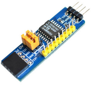 , , , . BMP180 I²C 8- GPIO PCF8574AT.
, PCF8574A ( PCF8574)
, , , . BMP180 I²C 8- GPIO PCF8574AT., PCF8574A ( PCF8574)
0x38 ( PCF8574 0x20 ), . , , - 8 , . 8 , 64 GPIO. , . I²C .I²C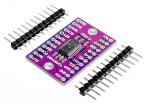 , BMP180,
 , GPIO, . : - I²C SDA SCL, . , , 8 BMP180, c A0-A2
, BMP180, 0x77 (.. 0xee ) ? , (), TCA9548A - , . () 8 , . 0x70 (. 0xe0 ipmitool ). A0=A1=A2=1 0x77 , , , BMP180. , TCA9548A, I²C 56 -. , . , , .ipmitool(1) v1.8.15, () FreeBSD 10. , , stderr, stdout. . , - IPMI (perl, Python), raw-.ipmitool(1) (623/tcp), JPI2C , . IPMI . , , , , (, Raspberry Pi microSD- read-only)., , « ». , Power Fail SNMP-, . : , , , . — .
I²C
«» I²C- , , . «» I²C-, , . ? , , . , , . FAQ ID 9492 , (, , )
0x38, 0x39, 0x3a, ... ( IPMI, ).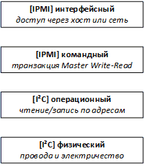 IPMI I²C: , Master Write-Read IPMI. IPMI 2.0 22.11, . , I²C — , . IPMI Master Write-Read : «-» , IPMI ( 30 ). , () BMC I²C () BMC , .. .
, IPMI Master Write-Read ( ) , BMC , I²C: I²C, . , - 4- I²C- IPMI, . , , , , , :)
, SMBus, , I²C , Write/Read Block. SMBus, IPMI , . , IPMI SMBus , , .
Security
BMC-, , . , , «» , KVM - . BMC- , BMC ( BIOS).
-
, , - , c :
, , :
, , , , , . , .
, Corsair Link Commander Mini USB HID, SMBus, «» PMBus, . SMBus, 0x98 (PMBUS_REVISION). , . PMBus . , , ( ) .
, «» community- , . , , .. . , , .
In some ways, Corsair Link is one of our best kept secrets. It had a very rocky start, but continued and continuing development has turned it into an extremely useful combination of hardware and software. It allows you to connect several products within our ecosystem to a software-based control panel, but there's so much more to it than that.
, , , , , . , .
, Corsair Link Commander Mini USB HID, SMBus, «» PMBus, . SMBus, 0x98 (PMBUS_REVISION). , . PMBus . , , ( ) .
, «» community- , . , , .. . , , .
, community :
UPD:IPMI I²C —
, I²C ? USB- I²C/SMBus, USB HID.
x893 -: CP2112 - Silicon Labs MCP2221A - Microchip. , «A» 460 115. , CP2112EK $40, ADM00559 MCP2221 . , / , .
, , USB , USB HID . : , HID, , CDC, .. COM-. USB HID . , , Python. USB HID, Microchip Linux, . , :)
findings
- I²C, IPMI.
- « » I²C- (, , GPIO), .
- , I²C- , IPMI.
- BMC-, IPMI, I²C Master Write-Read, .
- , - .
- PMBus, I²C/SMBus.
Links
Intelligent Platform Management Interface Specification v2.0
www.intel.com/content/dam/www/public/us/en/documents/product-briefs/second-gen-interface-spec-v2.pdf
IPMItool
sourceforge.net/projects/ipmitool
I²C Bus ( telos)
www.i2c-bus.org
System Management Bus (SMBus) description
www.smbus.org/specs/smbdef.htm
PMBus, Power Management Bus
pmbus.org
FreeNAS, Enterprise-Grade Features, Open Source, BSD Licensed
www.freenas.org
SGPIO, Serial General Purpose Input/Output
www.wikipedia.org/wiki/SGPIO
SuperMicro FAQ ID 9242, Monitoring of PSU using IPMITool
www.supermicro.com/support/faqs/faq.cfm?faq=9492
LM25056, System Power Measurement IC with PMBus
www.ti.com/product/LM25056
PCF8574A, Remote 8-Bit I/O Expander for I2C-Bus
www.ti.com/product/PCF8574A
TCA9548A, Low-Voltage 8-Channel I2C Switch With Reset
www.ti.com/product/TCA9548A
BMP180, Barometric Pressure Sensor
www.bosch-sensortec.com/bst/products/all_products/bmp180
, BMP180 Barometric Pressure Sensor
41j.com/blog/2015/01/bmp180-barometric-pressure-sensor
, . SuperMicro ( X8)
3nity.ru/viewtopic.php?p=135736#p135736
FreeNAS, Script to control fan speed in response to hard drive temperatures
forums.freenas.org/index.php?threads/script-to-control-fan-speed-in-response-to-hard-drive-temperatures.41294
Computer Cheese, IPMI Messaging Support commands,
computercheese.blogspot.com/2013/05/ipmi-messaging-support-commands.html
Corsair Link
www.corsair.com/en/support/faqs/corsair-link
EEVblog Electronics Community Forum
www.eevblog.com/forum/chat/corsair-link
Source: https://habr.com/ru/post/400729/
All Articles