SG90 servo control without microcontroller
I got my hand on the popular inexpensive SG90 servo. And thought to manage it, but without a microcontroller. In this article I will explain the course of the developer’s thoughts when implementing one of the solutions.
Who cares, I ask under the cat.
Idea
It is necessary to control the servo, but without a microcontroller.
Knowledge
Everyone knows that experience and knowledge help create and find solutions. There are many examples of the use of a servo with controllers on the pages of Hiktaims. They are described in detail about the servo control system. We will take this experience of other developers for the knowledge we need to solve the problem. The SG90 servo drive is controlled by a PWM signal whose parameters determine the position of the rotor. The PWM period is about 20 ms, the duration of the control signal is from 500 to 2100 μS.
')
Task
Idea and knowledge give rise to a problem that needs to be solved. We formulate the problem for the realization of the idea. This is something like a technical assignment. It seems that everything is simple, it is necessary to take a pulse generator with a variable duty cycle, connect the power to the servo drive, and send a control signal from the generator. We note in particular that there are changes in the duty cycle in the requirements - that is, there must be controls or a user interface.
Implementation
Here the torments of creativity begin: what to take and where to get? You can find a ready-made laboratory pulse generator, for example, G5-54 with handles, buttons, set the necessary parameters, connect the generator to the servo drive. However, it is cumbersome and not everyone can afford such luxury. Therefore, developers, relying on their experience and knowledge, are trying to combine the desire (idea-task) and possibilities (material and creative) for the realization of the task. Material opportunities are
Search for alternatives
Using the Internet, look for options that offers NETWORK. Let's set in search: “a generator of rectangular pulses with a variable duty cycle”. We get a lot of options, both with the use of integrated timers NE555 (domestic analogue of KR1006VI1), and on logic chips. Of all the variety, I chose the inverter generator option with a Schmitt trigger at the input. Firstly, it is the simplest, secondly, it requires a minimum of details and the most interesting uses a single logical element of six, for example, if you use a 74HC14 chip.
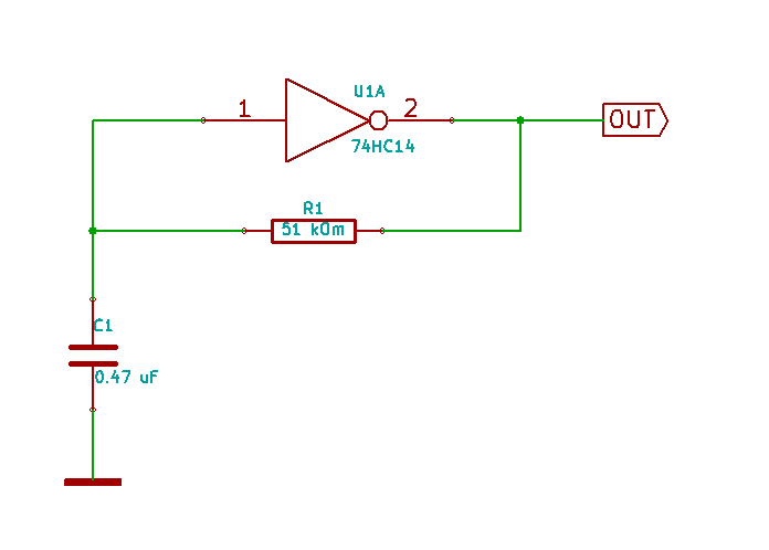
The scheme of such a generator looks like this:

Some theory
The theory says that the frequency of such a generator is f = 1 / T = 1 / (0.8 * R * C). To obtain the required frequency, you must select the nominal value of one of the elements that set the frequency. Since the logical element is made according to CMOS technology, it has a large input resistance, so elements defining small operating currents can be used. We choose the capacitance C1 from a number of common denominations, for example, 0.47 μF. Then, to obtain the required frequency (50 Hz), the resistor should be approximately 53 kΩ, but there is no such resistor in the standard row, so we choose 51 kΩ.
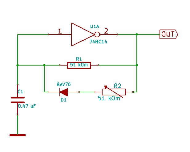
At the output of such a generator, a signal is formed close to the meander, so we need to adjust the circuit so that it meets the requirements of the task. To obtain an adjustable pulse duration at the output, it is necessary to change the mode of recharging the capacitor from a high level at the output, namely, to reduce the recharge time. To do this, add two more elements to the circuit: a diode and a variable resistor. Any low-power pulsed diode will do.
Then the scheme will take the following form:
It would seem: everything, the problem is solved, but in the extreme positions of the variable resistor the behavior of the servo is unstable. This is due to the fact that the value of the pulse duration, in the extreme positions of the variable resistor, does not correspond to the required one. Personally, I also do not like the use of a variable resistor, so I want to change the control interface by adding a new “Wishlist” to the technical task, for example, so that the duty cycle varies depending on the illumination. There is a simple and inexpensive solution for this: use the GL55xx photoresistor as a regulating element (used in Arduino projects), the change in resistance of which lies in a wide range.
Next comes the fun part. There are no calculated formulas for obtaining resistance values that provide the required pulse durations, therefore, at the level of intuition (experimentally, using a variable resistor), we determine the resistance values at which the required pulse widths are set. Then we change the circuit so that when the resistance of the photoresistor changes, the total resistance changes, setting the required pulse durations.
The final scheme takes the following form:
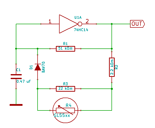
Explanation of the final scheme
Capacitor C1 nominal 0.47 microfarads, determines the time of recharging. Resistor R1 with a nominal value of 51 kΩ sets the basic pulse repetition frequency in the region of 50 Hz. The combination of resistors R2-R4 in total will vary in the range from 2.5 kΩ to 24 kΩ, depending on the illumination. Together with the diode D1, these resistors will affect the recharging time of the capacitor C1 under the action of a positive pulse at the output of the logic element, thereby determining its duration.
Result
By connecting this generator to the control input of the servo drive, we will be able to control it by changing the illumination of the photoresistor. On the video you can see what came out of it:
It would seem that everything, but I can offer the development of this development. Since we used only one of the six logical elements of the microchips included in the case, it is possible to assemble five more generators and connect them to other servos. By connecting to the actuating levers of the servo actuators of the valve, which will block the luminous flux of the photoresistors controlling the other servo drives, you can get a funny behavior of the servo actuators, but I propose to conduct this experiment independently.
Dare and good luck!
Source: https://habr.com/ru/post/400631/
All Articles