Recampling II. Comparison of the operation of digital and analog filters of high order in the sound path and answers to questions
Attention - this publication is a clarification of the first part of the article and the answer to the questions from its comments. To understand what it is about, you need to familiarize yourself with the previous one if you have not done this yet .
Among the numerous comments to my last article were two very characteristic questions - from a group of people whom I can conditionally refer to the category of “practitioners”, and a person who, perhaps unwillingly, voiced a position close to many audiophiles.
It became clear to me that not everyone understands the explanations based on the theory of the spectral decomposition of the signal and further manipulation of the harmonics. Below, I made an attempt to highlight some of the questions from the previous article even more clearly.
Why digital filters in sound processing paths are not always evil
Why high-order analog filters are difficult to implement in serial devices
I will try to reveal both these noteworthy topics in as accessible a language as possible.
')
Question one from FreeMind2000 :
Yes, the Nyquist theorem is correct, but if even at two points it is possible to restore the frequency of a periodic signal, which is not theleast important , then this does not mean that the DAC can do this successfully, especially without the use of filters! This is all the more so for a complex signal, which is a superposition of a large number of harmonics, sometimes abruptly appearing and disappearing or changing tone.
In order to gain insight into the essence of the problem, it is necessary to understand the following - having performed the act of digitizing the operation, we thereby irrevocably distorted the signal. Even if you use the perfect microphone, amplifier and analog-to-digital converter.
Let us, for clarity, move from theory to practice and depict the shape of the original signal in the background of the signal coming from the ideal DAC.
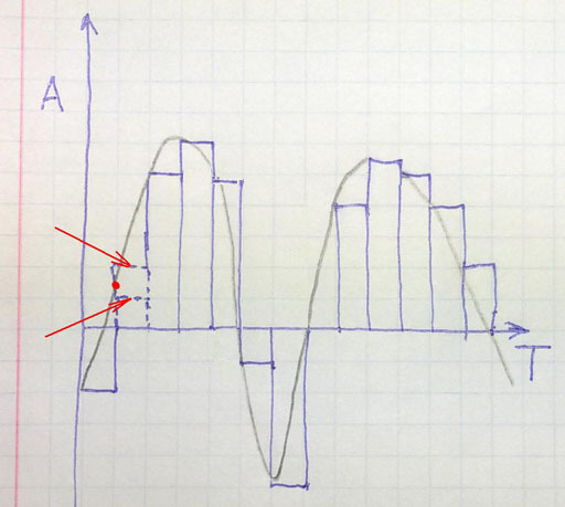
Let me remind you that the DAC orin Russian DAC at regular intervals extracts the digitized value and fixes it at its output. As a result, we get a stepped signal. In our figure, the minimum vertical and horizontal pitch is one square. For the width of the steps corresponds to the frequency of digitization, and the vertical resolution is determined by the width of the ADC. How the quality of digitized signals depends on it can be seen in the example of digitizing the second bit. The real value lies almost in the middle between two valid integer values, which can be assigned to the ADC sample. It chose the bottom one, and we got a very big mistake. I hope everyone now understands why even in an ideal ADC, the low order cannot be considered meaningful.

Let's see what makes our chip from SONY. She increased the sampling rate 4 times. Moreover, it also added permissions vertically due to the fact that it increased the signal width from 16 to 18 bits. Further, using the filter, the signal is approximated and three intermediate points are inserted, and their installation accuracy is higher both horizontally and vertically 4 times than before the transformations made. Accurate placement of these points is the filter. The higher his order, the more qualitatively he produces the approximation.
However, after performing these operations, we still have a stepped structure, which is not depicted in the figure - instead of them I have depicted bullet points in the first three samples. And here the simplest low-frequency filter of the second and third order comes in, which smoothes these steps. The result is shown below:

Here the pencil curve is the original signal.
The red curve is the signal at the output of a 16 bit DAC.
The green part of the curve is what we got after the resampling operation and the subsequent application of the simplest filter.
I hope that FreeMind2000 and its supporters would agree that “pure, undistorted, step sound from the DAC output” looks less like the original than that distorted by digital perversions?
I note that the first left oscillation has the main harmonic somewhere in the region of 44/7 = 6 kilohertz, while it looks very distorted when digitized at a frequency of 44 KHz. Can you imagine how much a signal with a frequency of 17 kilohertz will resemble the original?
It is important to note here that, if desired, digital filters may not touch the reference points obtained from a 16-bit DAC - just place auxiliary ones between them, smoothing the curve at their discretion.
For a number of reasons, this cannot be done using high-order analog filters instead of numbers. Here, by the way, it's time to get to the questionor rather the statement made by AntonSor and ardently supported by dernuss
AntonSor comment text :
In order not to deal with all the holidays in an educational program, I only briefly mention that high-quality high-order filters cannot be built on general-purpose operational amplifiers, which include TI TL074 from TI.
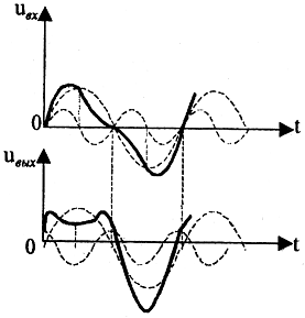
It is quite important that the analog filters of low frequencies of high orders generate serious phase distortions, especially in the region of the cutoff frequency. I will also not prove this well-known truth with a succession of long formulas to our esteemed comrades, I’ll just give you a picture from one of my previous articles that shows how hard phase distortions deal with the waveform.
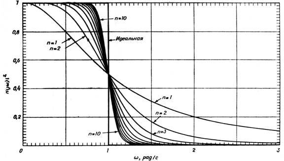
And in conclusion,at the request of the workers , I’ll dwell on the reason why, without precisely selected ratings of parts, high order filters will not give beautiful ideal calculated characteristics, as in the below normalized frequency dependence of signal attenuation on the Butterfort filter order in logarithmic coordinates.
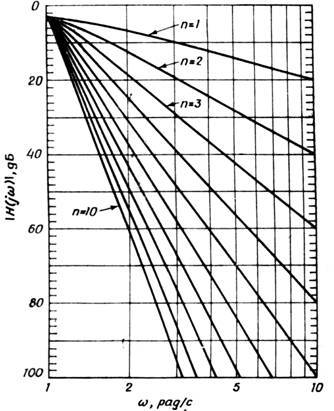
In order to build a filter that approaches this parameter to the digital one described in the previous article, it is necessary to use the eighth or tenth order.
The following shows the transfer function of the ideal low-pass filter and Butterfort filters of various orders.
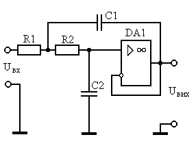
How are such filters usually built? Very simply - a second-order low-pass filter is constructed, for example, according to the scheme given below ...
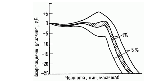
Ok, let's look at the graph that shows how the parameters of the second-order Butterworth filter change.Note that the horizontal scale shows the linear scale of the variation in the ratings of the components in the feedback circuit.
Now imagine a superposition of the transfer characteristics of several such links with different cutoff frequencies due to the spread of the components.

It is not difficult to guess that we will not get as a result of the effect of increasing the filter slope depending on the order. In addition, we will generate extra humps on the characteristic that will cause intermodulation distortion.
In fact, the situation is even worse because the spread affects not only the cutoff frequency, but also the other parameters of each of the links. The resulting filtered soundperformed by cancer, swan and pike may be suitable for the dynamics of the output of the regenerative receiver, but trying to use it in a high-quality DAC will cause nothing but unhealthy laughter from potential buyers.
Instead of an afterword I publish a couple of pictures from the user zerg59 , who was not too lazy to model

The signal at the output of the DAC with a frequency of 0.45 of the sampling rate. Well viewed "zero beats"

Same signal, last resampling and tenth order digital filter
PS I could not refrain from using a fragment of the picture from the excellent commentary on the first part from the user Refridgerator in the header.
Among the numerous comments to my last article were two very characteristic questions - from a group of people whom I can conditionally refer to the category of “practitioners”, and a person who, perhaps unwillingly, voiced a position close to many audiophiles.
It became clear to me that not everyone understands the explanations based on the theory of the spectral decomposition of the signal and further manipulation of the harmonics. Below, I made an attempt to highlight some of the questions from the previous article even more clearly.
So, under the cut, consider two topics:
Why digital filters in sound processing paths are not always evil
Why high-order analog filters are difficult to implement in serial devices
I will try to reveal both these noteworthy topics in as accessible a language as possible.
')
Why digital filters in sound processing paths are not always evil
Question one from FreeMind2000 :
Enlighten not a specialist? ;)
The initial chain is:
1) Live sound -> ADC (16bit, 44.1 KHz) -> CD
2) CD -> 16bit -> Microcontroller -> DAC (16bit, 44.1 KHz) -> recovered sound
After upgrade:
2) CD -> 16bit -> Microcontroller + (A certain filter converts 16bit to 18, 44.1 KHz to 44.1 * 4) -> DAC (18bit, 44.1 * 4 KHz) -> restored sound
Those. in the upgrade we just:
1. Put more expensive DAC (with increased sampling rate and bit depth)
2. By inventing (interpolating) the missing samples on the CD time scale, the number of reproducible samples was increased.
Right?
Then, attention, question:
1. Did we really improve the sound quality by adding samples that in the original (live sound) could be different from those that we invented (interpolated)? After all, what we recorded at a frequency of 44.1 KHz was actually recorded by the microphone, and we did not know what was between the recorded samples.
2. How far is our fantasy (I apologize, interpolation :) can get us? Those. theoretically, we can interpolate both 8bit sound and 4x ...
3. And what kind of quality improvement are we talking about?
For a person, the average frequency threshold of perceived sound is 20 kHz, we reproduce at a frequency of 44.1 kHz - does it make any sense to increase further? .. Increasing the fidelity of reproduction by 2 bits is the only thing that is relevant to real quality improvement, well, and does anyone know How many discharges can the human ear distinguish? ;)
Yes, the Nyquist theorem is correct, but if even at two points it is possible to restore the frequency of a periodic signal, which is not the
In order to gain insight into the essence of the problem, it is necessary to understand the following - having performed the act of digitizing the operation, we thereby irrevocably distorted the signal. Even if you use the perfect microphone, amplifier and analog-to-digital converter.
Let us, for clarity, move from theory to practice and depict the shape of the original signal in the background of the signal coming from the ideal DAC.
Let me remind you that the DAC or
Let's see what makes our chip from SONY. She increased the sampling rate 4 times. Moreover, it also added permissions vertically due to the fact that it increased the signal width from 16 to 18 bits. Further, using the filter, the signal is approximated and three intermediate points are inserted, and their installation accuracy is higher both horizontally and vertically 4 times than before the transformations made. Accurate placement of these points is the filter. The higher his order, the more qualitatively he produces the approximation.
However, after performing these operations, we still have a stepped structure, which is not depicted in the figure - instead of them I have depicted bullet points in the first three samples. And here the simplest low-frequency filter of the second and third order comes in, which smoothes these steps. The result is shown below:
Here the pencil curve is the original signal.
The red curve is the signal at the output of a 16 bit DAC.
The green part of the curve is what we got after the resampling operation and the subsequent application of the simplest filter.
I hope that FreeMind2000 and its supporters would agree that “pure, undistorted, step sound from the DAC output” looks less like the original than that distorted by digital perversions?
I note that the first left oscillation has the main harmonic somewhere in the region of 44/7 = 6 kilohertz, while it looks very distorted when digitized at a frequency of 44 KHz. Can you imagine how much a signal with a frequency of 17 kilohertz will resemble the original?
It is important to note here that, if desired, digital filters may not touch the reference points obtained from a 16-bit DAC - just place auxiliary ones between them, smoothing the curve at their discretion.
For a number of reasons, this cannot be done using high-order analog filters instead of numbers. Here, by the way, it's time to get to the question
Why high-order analog filters are difficult to implement in serial devices
AntonSor comment text :
In order to cut off everything that lies beyond the limits of the sound range (20 kHz) and get attenuation at 40 dB at 44 kHz, and with a smooth phase response, a 7-order filter is required, which is a Butterworth filter; these are three operational amplifiers and 10 5% resistors and capacitors per channel. Yes, cumbersome, but not impossible. Two quad type operational amplifier TL074. In the amateur receiver direct conversion is more (in the phase shifter).
In order not to deal with all the holidays in an educational program, I only briefly mention that high-quality high-order filters cannot be built on general-purpose operational amplifiers, which include TI TL074 from TI.
It is quite important that the analog filters of low frequencies of high orders generate serious phase distortions, especially in the region of the cutoff frequency. I will also not prove this well-known truth with a succession of long formulas to our esteemed comrades, I’ll just give you a picture from one of my previous articles that shows how hard phase distortions deal with the waveform.
And in conclusion,
In order to build a filter that approaches this parameter to the digital one described in the previous article, it is necessary to use the eighth or tenth order.
The following shows the transfer function of the ideal low-pass filter and Butterfort filters of various orders.
How are such filters usually built? Very simply - a second-order low-pass filter is constructed, for example, according to the scheme given below ...
Ok, let's look at the graph that shows how the parameters of the second-order Butterworth filter change.
Now imagine a superposition of the transfer characteristics of several such links with different cutoff frequencies due to the spread of the components.
It is not difficult to guess that we will not get as a result of the effect of increasing the filter slope depending on the order. In addition, we will generate extra humps on the characteristic that will cause intermodulation distortion.
In fact, the situation is even worse because the spread affects not only the cutoff frequency, but also the other parameters of each of the links. The resulting filtered sound
Instead of an afterword
Instead of an afterword I publish a couple of pictures from the user zerg59 , who was not too lazy to model
Labview Audio Path with Signal Generator, ADC, DAC, and Resampler
The signal at the output of the DAC with a frequency of 0.45 of the sampling rate. Well viewed "zero beats"
Same signal, last resampling and tenth order digital filter
PS I could not refrain from using a fragment of the picture from the excellent commentary on the first part from the user Refridgerator in the header.
Source: https://habr.com/ru/post/400527/
All Articles