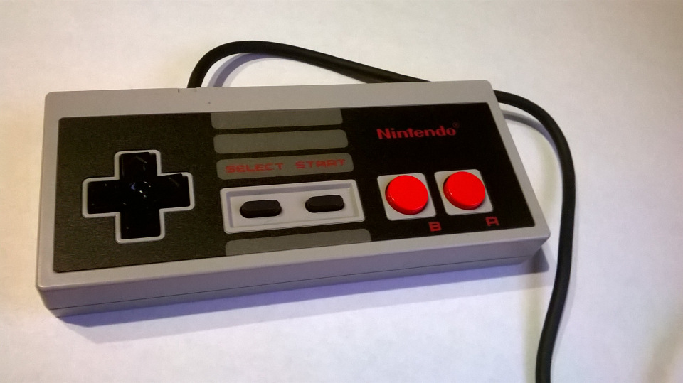
Connecting the gamepad from Nintendo Classic Mini to the Raspberry pi
Holidays are coming to an end, which means it's time to regret the liver and turn on the head. So I came up with another idea. After I connected the gamepad from Dendy (he's a joystick, he's a controller, he's a joystick, he's a gaming console, etc.) geektimes.ru/post/281520 , I thought about connecting the second to Raspberry pi. I didn’t want to buy the second junk with jamming buttons, and then just by the way, they threw it on the shelves of the Nintendo Classic Mini, so how did they dump it? The very purpose of buying an emulator for 4K was not, but I decided to buy a gamepad. Fortunately I managed to buy it, was the last in the store. Those who are interested in what came out of it can click on the button below.
Here is a direct link to the proof if the regular one is not activated.
There is no secret that this gamepad can be connected to both the Wii and the Wii U, which means it can be interrogated via the i2c interface. What is gratifying is that the gamepad is powered by 3.3 V, which means you don’t have to bother with matching voltage levels. To connect the gamepad to the Raspberry pi, I decided to buy wiimote connectors for aliexpress, which are soldered on the board from him. Although the package had 2 connectors, and they were in a common pimple, one of the connectors came in disrepair. No tin cans do here. After everything was soldered, it was necessary to check whether it works. For this, I decided to use the utilities from the i2c-tools package. The idea was to determine the device at the address - 52. When launching i2cdetect, I saw the cherished:
')
My heart immediately became warmer (as if an unknown girl smiled at you in the spring on the street), it means it works. Next, it was necessary to google about connecting peripherals to the Wii. I found an example of how a nunchuk from a Wii connects to the Raspberry pi. From this example, I learned that the gamepad should be initialized by writing 0x40 zero to the register, and then before each reading you just need to write down the zero and read the first 6 bytes.
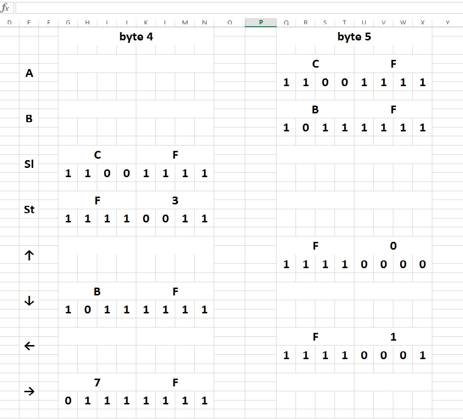
In this case, I also faced the choice of the library for the work of i2c. Since I didn’t work with the bcm2835 library, I decided to use the library used in the example — it is the WirinPi library. Everything worked out with her. Experienced I found out that the information about the buttons is contained in 4 and 5 bytes (if we count the bytes from zero). Information about the select, start, down, right buttons is in the fourth byte, and information about the A, B, up, left buttons is in the fifth byte. Moreover, information about the select, down, right buttons is in the higher 4 bits of a byte, and information about the start button is in the lower ones. The same is the 5th byte, the information about the A, B buttons is in the high 4 bits of the byte, and the information about the up, left buttons is in the low. Here are the codes for the buttons: A - 0xcf, B - 0xbf, up - 0xf0, left - 0xf1, select - 0xcf, start - 0xf3, down - 0xbf, right - 0x7f. The result of the joint pressing of the buttons, information about which is in one byte and in one bits, is a logical "AND" of their codes. So for example, pressing buttons A and B together gives the value 0x8f.
Here is the link to the table:
Next, I wrote a small test program for reading the buttons, below I will give its listing in full and explain what is there with it:
At the very beginning, variables are declared, which will be used to determine the state of a particular button. It is important that the variables be of type char, otherwise when the bitwise shift is to the left, 4 zeros will be added, that's all. The interpretation will be wrong. No matter how funny it may sound, you must use the spell .
Further, in the main body of the program, the WiringPi library is initialized - wiringPiSetup (); and then the device i2c address is specified - 0x52. Next comes the gamepad initialization:
Well, then already in the body of the cycle, 6 bytes are read, and before reading, each time zero is written. And after that, the definition of the pressed button occurs. In general, all this code and migrated to the emulator files.
Like last time, the library initialization is registered in the fceu.c file:
Well, then all the changes relate only to the file input.c. Initially, in the int FCEUI_Initialize (void) function, the modes of operation of gpio ports for working with the old gamepad (from Simba's) are set, and the gamepad is initialized.
In the beginning, you also need to declare variables, with the help of which button presses will be determined.
In the static DECLFW function (B4016), the gate is fed to the old gamepad, the new gate is not needed:
When creating a test program, I could not solve the problem with the definition of jointly pressed buttons, information about which is in one byte and in one bit. As a result, I applied the switch case construction, instead of if else.
Well, the function itself read the state of the buttons:
I in one cycle combined reading buttons from both gamepads, well, you will think that 2 extra bytes are read, it does not matter, but everything happens at the same time. And there are no delays.
In general, everything is fine.
PS: As I recall, that tomorrow at work, already distorts.
PPS I forgot to add that in order to successfully compile, in the Makefile (formed after running the Configure command), which is located in the src directory, you need to add -lwiringPi -lm -lrt to the place where the dependencies on the libraries are written. Line:
Here is a direct link to the proof if the regular one is not activated.
There is no secret that this gamepad can be connected to both the Wii and the Wii U, which means it can be interrogated via the i2c interface. What is gratifying is that the gamepad is powered by 3.3 V, which means you don’t have to bother with matching voltage levels. To connect the gamepad to the Raspberry pi, I decided to buy wiimote connectors for aliexpress, which are soldered on the board from him. Although the package had 2 connectors, and they were in a common pimple, one of the connectors came in disrepair. No tin cans do here. After everything was soldered, it was necessary to check whether it works. For this, I decided to use the utilities from the i2c-tools package. The idea was to determine the device at the address - 52. When launching i2cdetect, I saw the cherished:
')
i2cdetect -y 1 0 1 2 3 4 5 6 7 8 9 abcdef 00: 03 04 05 06 07 -- -- -- -- -- -- -- -- 10: -- -- -- -- -- -- -- -- -- -- -- -- -- -- -- -- 20: -- -- -- -- -- -- -- -- -- -- -- -- -- -- -- -- 30: -- -- -- -- -- -- -- -- -- -- -- -- -- -- -- -- 40: -- -- -- -- -- -- -- -- -- -- -- -- -- -- -- -- 50: -- -- 52 -- -- -- -- -- -- -- -- -- -- -- -- -- 60: -- -- -- -- -- -- -- -- -- -- -- -- -- -- -- -- 70: -- -- -- -- -- -- -- -- My heart immediately became warmer (as if an unknown girl smiled at you in the spring on the street), it means it works. Next, it was necessary to google about connecting peripherals to the Wii. I found an example of how a nunchuk from a Wii connects to the Raspberry pi. From this example, I learned that the gamepad should be initialized by writing 0x40 zero to the register, and then before each reading you just need to write down the zero and read the first 6 bytes.
In this case, I also faced the choice of the library for the work of i2c. Since I didn’t work with the bcm2835 library, I decided to use the library used in the example — it is the WirinPi library. Everything worked out with her. Experienced I found out that the information about the buttons is contained in 4 and 5 bytes (if we count the bytes from zero). Information about the select, start, down, right buttons is in the fourth byte, and information about the A, B, up, left buttons is in the fifth byte. Moreover, information about the select, down, right buttons is in the higher 4 bits of a byte, and information about the start button is in the lower ones. The same is the 5th byte, the information about the A, B buttons is in the high 4 bits of the byte, and the information about the up, left buttons is in the low. Here are the codes for the buttons: A - 0xcf, B - 0xbf, up - 0xf0, left - 0xf1, select - 0xcf, start - 0xf3, down - 0xbf, right - 0x7f. The result of the joint pressing of the buttons, information about which is in one byte and in one bits, is a logical "AND" of their codes. So for example, pressing buttons A and B together gives the value 0x8f.
Here is the link to the table:
Next, I wrote a small test program for reading the buttons, below I will give its listing in full and explain what is there with it:
#include <stdio.h> #include <unistd.h> #include <stdlib.h> #include <wiringPi.h> #include <wiringPiI2C.h> #include <errno.h> char i, a, b, c, d, state; char bytes[6]; int main(void) { wiringPiSetup(); int fd = wiringPiI2CSetup(0x52); wiringPiI2CWriteReg8(fd, 0x40, 0x00); delayMicroseconds(20); while(1) { state = 0; wiringPiI2CWrite(fd, 0x00); delayMicroseconds(100); for (i=0; i<6; i++) { bytes[i] = wiringPiI2CRead(fd); } a = bytes[5] >> 4; b = bytes[5] << 4; c = bytes[4] >> 4; d = bytes[4] << 4; if (a == 0xc) state ^= (1 << 0); if (a == 0xb) state ^= (1 << 1); if (c == 0xc) state ^= (1 << 2); if (d == 0x30) state ^= (1 << 3); if (b == 0x00) state ^= (1 << 4); if (c == 0xb) state ^= (1 << 5); if (b == 0x10) state ^= (1 << 6); if (c == 0x7) state ^= (1 << 7); printf("%x \n", state); } return 0; } At the very beginning, variables are declared, which will be used to determine the state of a particular button. It is important that the variables be of type char, otherwise when the bitwise shift is to the left, 4 zeros will be added, that's all. The interpretation will be wrong. No matter how funny it may sound, you must use the spell .
Further, in the main body of the program, the WiringPi library is initialized - wiringPiSetup (); and then the device i2c address is specified - 0x52. Next comes the gamepad initialization:
wiringPiI2CWriteReg8(fd, 0x40, 0x00); delayMicroseconds(20); Well, then already in the body of the cycle, 6 bytes are read, and before reading, each time zero is written. And after that, the definition of the pressed button occurs. In general, all this code and migrated to the emulator files.
Like last time, the library initialization is registered in the fceu.c file:
int FCEUI_Initialize(void) { if(!FCEU_InitVirtualVideo()) return 0; memset(&FSettings,0,sizeof(FSettings)); FSettings.UsrFirstSLine[0]=8; FSettings.UsrFirstSLine[1]=0; FSettings.UsrLastSLine[0]=231; FSettings.UsrLastSLine[1]=239; FSettings.SoundVolume=100; FCEUPPU_Init(); X6502_Init(); wiringPiSetup(); return 1; } Well, then all the changes relate only to the file input.c. Initially, in the int FCEUI_Initialize (void) function, the modes of operation of gpio ports for working with the old gamepad (from Simba's) are set, and the gamepad is initialized.
pinMode (0, OUTPUT); pinMode (2, OUTPUT); pinMode (3, INPUT); digitalWrite (0, HIGH); digitalWrite (2, LOW); fd = wiringPiI2CSetup(0x52); wiringPiI2CWriteReg8(fd, 0x40, 0x00); usleep(20); In the beginning, you also need to declare variables, with the help of which button presses will be determined.
In the static DECLFW function (B4016), the gate is fed to the old gamepad, the new gate is not needed:
if (LastStrobe==0) { digitalWrite (0, LOW); } When creating a test program, I could not solve the problem with the definition of jointly pressed buttons, information about which is in one byte and in one bit. As a result, I applied the switch case construction, instead of if else.
Well, the function itself read the state of the buttons:
void FCEU_UpdateInput(void) { joy[0] = 0; joy[1] = 0xff; wiringPiI2CWrite(fd, 0x00); usleep(100); for (i = 0; i <= 7; i++) { bytes[i] = wiringPiI2CRead(fd); joy[1] ^= digitalRead(3) << i; digitalWrite (2, HIGH); delayMicroseconds (20); digitalWrite (2, LOW); delayMicroseconds (20); } a = bytes[5] >> 4; b = bytes[5] << 4; c = bytes[4] >> 4; d = bytes[4] << 4; switch (a){ case 0xc: joy[0] ^= (1 << 0); break; case 0xb: joy[0] ^= (1 << 1); break; case 0x8: joy[0] ^= (1 << 0); joy[0] ^= (1 << 1); break; } switch (b){ case 0x00: joy[0] ^= (1 << 4); break; case 0x10: joy[0] ^= (1 << 6); break; case 0x20: joy[0] ^= (1 << 4); joy[0] ^= (1 << 6); break; } switch (c){ case 0xc: joy[0] ^= (1 << 2); break; case 0xb: joy[0] ^= (1 << 5); break; case 0x7: joy[0] ^= (1 << 7); break; case 0x8: joy[0] ^= (1 << 2); joy[0] ^= (1 << 5); break; case 0x4: joy[0] ^= (1 << 2); joy[0] ^= (1 << 7); break; case 0x3: joy[0] ^= (1 << 5); joy[0] ^= (1 << 7); break; } switch (d){ case 0x30: joy[0] ^= (1 << 3); break; } digitalWrite (0, HIGH); } I in one cycle combined reading buttons from both gamepads, well, you will think that 2 extra bytes are read, it does not matter, but everything happens at the same time. And there are no delays.
In general, everything is fine.
PS: As I recall, that tomorrow at work, already distorts.
PPS I forgot to add that in order to successfully compile, in the Makefile (formed after running the Configure command), which is located in the src directory, you need to add -lwiringPi -lm -lrt to the place where the dependencies on the libraries are written. Line:
LIBS = Source: https://habr.com/ru/post/400445/
All Articles