We dive deep into: from CSS to the transistor
70 years ago, on December 16, 1947, in the Bell Labs laboratories, John Bardeen and Walter Brattein, under the leadership of William Shockley, created the first active bipolar transistor. On December 23, Brattein demonstrated that his colleagues put the first transistor amplifier. Therefore, this day is often called the Day of the transistor .
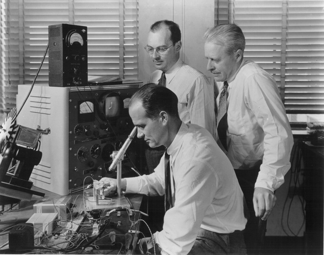
There is no need to talk about the significance of this event. The transistor is considered one of the most important inventions of the XX century, without which computers would still work on lamps and relays, and would occupy entire buildings. Shockley, Bardin and Brattein for their work received in 1956 the Nobel Prize in Physics. Over the past years, the transistor miniaturized to a few number of atoms. Each processor has billions of transistors, so the transistor can be called the most massive device created by mankind.
')
But what work does the transistor do for us? Let's go on a mental journey: let's follow the path from some high-level fintifli to our birthday party - a transistor.
What to take as a starting point? Well, at least drawing the button habrakata.
The button consists of background pixels, text, and a border. The code is set by the <a> tag, to which the CSS styling rules apply. For example, the CSS rule for corner rounding is applied to the border:

Thus, the boundary consists of four segments and four arcs (“quarters” of a circle).
For research, I took my favorite Firefox. Before FF starts drawing our button, it needs to do a lot of work on parsing and calculating the position of elements:
We will not dwell on these steps in detail. After them comes the actual drawing of the necessary elements.
The file nsCSSRenderingBorders.cpp is responsible for drawing the borders. And the general function of drawing borders is called (who would have thought): DrawBorders () . The function selects the best rendering method for different situations. We have a relatively simple case: there is a border-radius, but the borders on all sides are solid (solid) and of one color.
There are much more complicated options, for example, docking in corners with border-radius of different types of borders is dotted and dashed, see. DrawDashedOrDottedCorner () . There in the code completely
But back to our if. From the commentary we learn that in this case the border is drawn with the help of two rectangles - internal and external, then the created contour (path) is filled with the desired color.
Go to AppendRoundedRectToPath () in gfx / 2d / PathHelpers.cpp.
From the comment to the function, we learn that the corners are drawn at four control points by Bezier curves . Bezier curves are often used in computer graphics, including for drawing arcs of circles and ellipses. As we will further learn from the commentary, there are many options for choosing control points for constructing a curve. In this case, we need the points 0 and 3 to belong to the sides of the rectangle, the points 0, 1 and C lie on one straight line, the points 3, 2 and C - on the other. See drawing:

It remains for us to calculate the ratio of the lengths of the segments 01 / 0C and 32 / 3C. Here the authors use approximate calculations and get the alpha magic constant:
Unfortunately, the article with the algorithm for selecting control points to which the comment refers is not publicly available. But in general, it should be noted that in computer graphics algorithms often use approximation to improve performance. For example, the Brezenham algorithm allows drawing segments and circles not “head-on” - by solving the equations y = f (x), but by more cunning integer operations. The same with the fill, etc.
Further in the cycle we go from corner to corner, with the help of alpha we calculate the coordinates of control points and, finally, we call the functions of drawing the boundary line and arc of the angle:
But then it all depends on the backend 2D graphics, which uses Mozilla.
Gecko uses the platform-independent library Moz2D, which in turn can use one of the backends: Cairo, Skia, Direct2D, Quartz and NV Path. For example, for Windows, Direct2D, Cairo, Skia are available. Skia is also a Chromium backend. You can change the backend in about: config. Backends, in turn, can read everything on the CPU, and can use to some extent the hardware acceleration of the GPU. For example, Skia has its own OpenGL backend - Ganesh.
The Direct2D code is closed, so it's better to turn on Skia and see what it does. The function of drawing the cubic curve SkPath :: cubicTo is called. To construct a curve, it is split by the de Castelgio algorithm into a number of straight line segments, which are actually drawn (see core / SkGeometry.cpp).
Honestly, I didn’t manage to fully understand the interiors of Skia, so I took a step back - to AppendRoundedRectToPath (), where all operations take place on whole numbers - what could be easier?
Having opened the disassembled code, we have to find the operation of addition in it.
Aha Even such a person as far from ASM as I can easily guess that the operation ADD is responsible for addition. Take the first operation:
0x142B1863 - address in RAM
0x00 - opcode - processor instruction code. This Mozilla is compiled for x86, and by opening the x86 instruction table , we will see that code 00 means an 8-bit addition operation with the ADD mnemonic. The first operand can be a register or memory cell, the second - a register. The first operand is added to the second, the result is written to the first. Let me explain, just in case, that the register is a super-fast RAM inside the processor, for example, to store intermediate results of calculations.
The second byte is also 0x00 and is called MOD-REG-R / M. Its bits specify the operands and the addressing method.

MOD = 00b in combination with R / M = 000b means that indirect addressing is used.
REG = 000b means that the AL register is used (lower 8-bit EAX register)
[eax] - indicates that the addition is made with the memory cell, the address of which lies in the register EAX
How does the processor handle the ADD command?
According to the description of the Skylake microarchitecture, I made a (extremely simplified) list of steps:

The core of SkyLake. Image from en.wikichip.org .
I repeat, this is my very simplified description and does not claim to be accurate or complete. For further reference, I recommend reading the post Journey through the processor's computing pipeline and the article Processors of the Intel Core i7 family
Now it would be interesting to know what is happening in the ALU: how are the numbers added? Unfortunately, information on the specific implementation of the micro-architecture and the ALU is a trade secret of Intel, therefore, we turn further to the theory.
A device for adding two bits (i.e. a bit) is called an adder . The output is the sum and the carry bit.

Source: Wikipedia
Since in real life, we need to add numbers consisting of several digits, the adder must also accept the carry bit from the previous bit. This adder is called complete .
Source: Wikipedia
As can be seen from the figure, the adder is composed of logical elements: XOR, AND, OR. And each logical element can be implemented using multiple transistors. Or even a relay .

An example of the implementation of the full adder on CMOS transistors. A source
So we got to the transistor! Although, of course, not only ALUs, but also other processor units work on transistors, and most of all transistors are used in the cache memory as its cells.
In reality, the adder circuit in our processor can be constructed differently and be much more complicated. For example, already Intel 8008 45 years ago was able to calculate all the carry bits in advance in order to perform addition in parallel (the so-called parallel transfer adder). Who cares, read an interesting post about ALU Intel 8008 reverse engineering on Ken Shirriff's blog . Those. various optimizations are used: for example, multiplication is also beneficial to do not “head to head”.
PS Because I am an amateur (web developer), and C ++, ASM, I know the architecture of BT quite a bit - from the institute course, I could get it wrong. Please feel free to send comments.
There is no need to talk about the significance of this event. The transistor is considered one of the most important inventions of the XX century, without which computers would still work on lamps and relays, and would occupy entire buildings. Shockley, Bardin and Brattein for their work received in 1956 the Nobel Prize in Physics. Over the past years, the transistor miniaturized to a few number of atoms. Each processor has billions of transistors, so the transistor can be called the most massive device created by mankind.
')
But what work does the transistor do for us? Let's go on a mental journey: let's follow the path from some high-level fintifli to our birthday party - a transistor.
What to take as a starting point? Well, at least drawing the button habrakata.
HTML and CSS
The button consists of background pixels, text, and a border. The code is set by the <a> tag, to which the CSS styling rules apply. For example, the CSS rule for corner rounding is applied to the border:
border-radius: 3px; Thus, the boundary consists of four segments and four arcs (“quarters” of a circle).
Browser
For research, I took my favorite Firefox. Before FF starts drawing our button, it needs to do a lot of work on parsing and calculating the position of elements:
- Download HTML, parse, compile a DOM tree
- Download via CSS, conduct lexical analysis, parse
- Bind rules to page elements based on priority and inheritance
- For all visible DOM nodes, make up a tree of their rectangular areas - frames.
- For frames, calculate the size and location (see video )
- Make frames out of frames with regard to z-index and content type (<canvas>, SVG, <video>).
- Create a drawing list in order: background color, background image, border, descendants, outline.
Add. reading materials:
We will not dwell on these steps in detail. After them comes the actual drawing of the necessary elements.
Downloading the source code to find out what is happening there
You need to download the source code of Mozilla Firefox . According to the instructions, we obtain the Firefox source code from Mercurial and Visual Studio with the C ++ tools. In VS you need to connect symbols from symbols.mozilla.org in debugging settings. The code we are interested in lies obviously somewhere in / layout /.
In order to find the desired function, I set breakpoints in the code, then I ran Firefox. In the browser, I opened a simplified copy of the page, where there is only our button with styles, and in full screen mode so that the breakpoints do not work on the interface elements of the FF itself.
In order to find the desired function, I set breakpoints in the code, then I ran Firefox. In the browser, I opened a simplified copy of the page, where there is only our button with styles, and in full screen mode so that the breakpoints do not work on the interface elements of the FF itself.
The file nsCSSRenderingBorders.cpp is responsible for drawing the borders. And the general function of drawing borders is called (who would have thought): DrawBorders () . The function selects the best rendering method for different situations. We have a relatively simple case: there is a border-radius, but the borders on all sides are solid (solid) and of one color.
Our if
if (allBordersSame && mCompositeColors[0] == nullptr && mBorderStyles[0] == NS_STYLE_BORDER_STYLE_SOLID && !mAvoidStroke && !mNoBorderRadius) { // Relatively simple case. gfxRect outerRect = ThebesRect(mOuterRect); RoundedRect borderInnerRect(outerRect, mBorderRadii); borderInnerRect.Deflate(mBorderWidths[eSideTop], mBorderWidths[eSideBottom], mBorderWidths[eSideLeft], mBorderWidths[eSideRight]); // Instead of stroking we just use two paths: an inner and an outer. // This allows us to draw borders that we couldn't when stroking. For example, // borders with a border width >= the border radius. (ie when there are // square corners on the inside) // // Further, this approach can be more efficient because the backend // doesn't need to compute an offset curve to stroke the path. We know that // the rounded parts are elipses we can offset exactly and can just compute // a new cubic approximation. RefPtr<PathBuilder> builder = mDrawTarget->CreatePathBuilder(); AppendRoundedRectToPath(builder, mOuterRect, mBorderRadii, true); AppendRoundedRectToPath(builder, ToRect(borderInnerRect.rect), borderInnerRect.corners, false); RefPtr<Path> path = builder->Finish(); mDrawTarget->Fill(path, color); return; } There are much more complicated options, for example, docking in corners with border-radius of different types of borders is dotted and dashed, see. DrawDashedOrDottedCorner () . There in the code completely
smart comments
// radius.width // |<----------------->| // | | // | ___---+------------- // | __-- #|# ### // | _- ##|## ##### // | / ##+## ##+## // | / # P # ##### // | | #|# ### // | | __--+------------- // || _- ^ // || / | // | / first dot is filled // | | // | | // | | // | | // | | // +------+ // |## ##| // |## ##| // |## ##| But back to our if. From the commentary we learn that in this case the border is drawn with the help of two rectangles - internal and external, then the created contour (path) is filled with the desired color.
AppendRoundedRectToPath(builder, mOuterRect, mBorderRadii, true); AppendRoundedRectToPath(builder, ToRect(borderInnerRect.rect), borderInnerRect.corners, false); RefPtr<Path> path = builder->Finish(); mDrawTarget->Fill(path, color); Go to AppendRoundedRectToPath () in gfx / 2d / PathHelpers.cpp.
Again we set breakpoints
From the comment to the function, we learn that the corners are drawn at four control points by Bezier curves . Bezier curves are often used in computer graphics, including for drawing arcs of circles and ellipses. As we will further learn from the commentary, there are many options for choosing control points for constructing a curve. In this case, we need the points 0 and 3 to belong to the sides of the rectangle, the points 0, 1 and C lie on one straight line, the points 3, 2 and C - on the other. See drawing:
It remains for us to calculate the ratio of the lengths of the segments 01 / 0C and 32 / 3C. Here the authors use approximate calculations and get the alpha magic constant:
const Float alpha = Float(0.55191497064665766025); Unfortunately, the article with the algorithm for selecting control points to which the comment refers is not publicly available. But in general, it should be noted that in computer graphics algorithms often use approximation to improve performance. For example, the Brezenham algorithm allows drawing segments and circles not “head-on” - by solving the equations y = f (x), but by more cunning integer operations. The same with the fill, etc.
Further in the cycle we go from corner to corner, with the help of alpha we calculate the coordinates of control points and, finally, we call the functions of drawing the boundary line and arc of the angle:
aPathBuilder->LineTo(p0); aPathBuilder->BezierTo(p1, p2, p3); Add. reading material
Full code AppendRoundedRectToPath ()
void AppendRoundedRectToPath(PathBuilder* aPathBuilder, const Rect& aRect, const RectCornerRadii& aRadii, bool aDrawClockwise) { // For CW drawing, this looks like: // // ...******0** 1 C // **** // *** 2 // ** // * // * // 3 // * // * // // Where 0, 1, 2, 3 are the control points of the Bezier curve for // the corner, and C is the actual corner point. // // At the start of the loop, the current point is assumed to be // the point adjacent to the top left corner on the top // horizontal. Note that corner indices start at the top left and // continue clockwise, whereas in our loop i = 0 refers to the top // right corner. // // When going CCW, the control points are swapped, and the first // corner that's drawn is the top left (along with the top segment). // // There is considerable latitude in how one chooses the four // control points for a Bezier curve approximation to an ellipse. // For the overall path to be continuous and show no corner at the // endpoints of the arc, points 0 and 3 must be at the ends of the // straight segments of the rectangle; points 0, 1, and C must be // collinear; and points 3, 2, and C must also be collinear. This // leaves only two free parameters: the ratio of the line segments // 01 and 0C, and the ratio of the line segments 32 and 3C. See // the following papers for extensive discussion of how to choose // these ratios: // // Dokken, Tor, et al. "Good approximation of circles by // curvature-continuous Bezier curves." Computer-Aided // Geometric Design 7(1990) 33--41. // Goldapp, Michael. "Approximation of circular arcs by cubic // polynomials." Computer-Aided Geometric Design 8(1991) 227--238. // Maisonobe, Luc. "Drawing an elliptical arc using polylines, // quadratic, or cubic Bezier curves." // http://www.spaceroots.org/documents/ellipse/elliptical-arc.pdf // // We follow the approach in section 2 of Goldapp (least-error, // Hermite-type approximation) and make both ratios equal to // // 2 2 + n - sqrt(2n + 28) // alpha = - * --------------------- // 3 n - 4 // // where n = 3( cbrt(sqrt(2)+1) - cbrt(sqrt(2)-1) ). // // This is the result of Goldapp's equation (10b) when the angle // swept out by the arc is pi/2, and the parameter "a-bar" is the // expression given immediately below equation (21). // // Using this value, the maximum radial error for a circle, as a // fraction of the radius, is on the order of 0.2 x 10^-3. // Neither Dokken nor Goldapp discusses error for a general // ellipse; Maisonobe does, but his choice of control points // follows different constraints, and Goldapp's expression for // 'alpha' gives much smaller radial error, even for very flat // ellipses, than Maisonobe's equivalent. // // For the various corners and for each axis, the sign of this // constant changes, or it might be 0 -- it's multiplied by the // appropriate multiplier from the list before using. const Float alpha = Float(0.55191497064665766025); typedef struct { Float a, b; } twoFloats; twoFloats cwCornerMults[4] = { { -1, 0 }, // cc == clockwise { 0, -1 }, { +1, 0 }, { 0, +1 } }; twoFloats ccwCornerMults[4] = { { +1, 0 }, // ccw == counter-clockwise { 0, -1 }, { -1, 0 }, { 0, +1 } }; twoFloats *cornerMults = aDrawClockwise ? cwCornerMults : ccwCornerMults; Point cornerCoords[] = { aRect.TopLeft(), aRect.TopRight(), aRect.BottomRight(), aRect.BottomLeft() }; Point pc, p0, p1, p2, p3; if (aDrawClockwise) { aPathBuilder->MoveTo(Point(aRect.X() + aRadii[RectCorner::TopLeft].width, aRect.Y())); } else { aPathBuilder->MoveTo(Point(aRect.X() + aRect.Width() - aRadii[RectCorner::TopRight].width, aRect.Y())); } for (int i = 0; i < 4; ++i) { // the corner index -- either 1 2 3 0 (cw) or 0 3 2 1 (ccw) int c = aDrawClockwise ? ((i+1) % 4) : ((4-i) % 4); // i+2 and i+3 respectively. These are used to index into the corner // multiplier table, and were deduced by calculating out the long form // of each corner and finding a pattern in the signs and values. int i2 = (i+2) % 4; int i3 = (i+3) % 4; pc = cornerCoords[c]; if (aRadii[c].width > 0.0 && aRadii[c].height > 0.0) { p0.x = pc.x + cornerMults[i].a * aRadii[c].width; p0.y = pc.y + cornerMults[i].b * aRadii[c].height; p3.x = pc.x + cornerMults[i3].a * aRadii[c].width; p3.y = pc.y + cornerMults[i3].b * aRadii[c].height; p1.x = p0.x + alpha * cornerMults[i2].a * aRadii[c].width; p1.y = p0.y + alpha * cornerMults[i2].b * aRadii[c].height; p2.x = p3.x - alpha * cornerMults[i3].a * aRadii[c].width; p2.y = p3.y - alpha * cornerMults[i3].b * aRadii[c].height; aPathBuilder->LineTo(p0); aPathBuilder->BezierTo(p1, p2, p3); } else { aPathBuilder->LineTo(pc); } } aPathBuilder->Close(); } But then it all depends on the backend 2D graphics, which uses Mozilla.
Graphics engine
Gecko uses the platform-independent library Moz2D, which in turn can use one of the backends: Cairo, Skia, Direct2D, Quartz and NV Path. For example, for Windows, Direct2D, Cairo, Skia are available. Skia is also a Chromium backend. You can change the backend in about: config. Backends, in turn, can read everything on the CPU, and can use to some extent the hardware acceleration of the GPU. For example, Skia has its own OpenGL backend - Ganesh.
The Direct2D code is closed, so it's better to turn on Skia and see what it does. The function of drawing the cubic curve SkPath :: cubicTo is called. To construct a curve, it is split by the de Castelgio algorithm into a number of straight line segments, which are actually drawn (see core / SkGeometry.cpp).
Add. reading materials
Machine code
Honestly, I didn’t manage to fully understand the interiors of Skia, so I took a step back - to AppendRoundedRectToPath (), where all operations take place on whole numbers - what could be easier?
Having opened the disassembled code, we have to find the operation of addition in it.
... 142B1863 00 00 add byte ptr [eax],al 142B1865 00 8D 43 FF 0F 84 add byte ptr [ebp-7BF000BDh],cl 142B186B 67 01 00 add dword ptr [bx+si],eax 142B186E 00 99 0F 57 C9 F7 add byte ptr [ecx-836A8F1h],bl 142B1874 F9 stc 142B1875 8B C3 mov eax,ebx 142B1877 8B CA mov ecx,edx 142B1879 99 cdq 142B187A F7 7C 24 28 idiv eax,dword ptr [esp+28h] ... Aha Even such a person as far from ASM as I can easily guess that the operation ADD is responsible for addition. Take the first operation:
142B1863 00 00 add byte ptr [eax],al0x142B1863 - address in RAM
0x00 - opcode - processor instruction code. This Mozilla is compiled for x86, and by opening the x86 instruction table , we will see that code 00 means an 8-bit addition operation with the ADD mnemonic. The first operand can be a register or memory cell, the second - a register. The first operand is added to the second, the result is written to the first. Let me explain, just in case, that the register is a super-fast RAM inside the processor, for example, to store intermediate results of calculations.
The second byte is also 0x00 and is called MOD-REG-R / M. Its bits specify the operands and the addressing method.
MOD = 00b in combination with R / M = 000b means that indirect addressing is used.
REG = 000b means that the AL register is used (lower 8-bit EAX register)
[eax] - indicates that the addition is made with the memory cell, the address of which lies in the register EAX
How does the processor handle the ADD command?
CPU
According to the description of the Skylake microarchitecture, I made a (extremely simplified) list of steps:
- X86 instructions are selected from the instruction cache L1 32KB in the pre-decoding buffer in blocks of 16 bytes
- Pre-coded commands are organized into an Instruction Queue (2x25) and entered into decoders.
- The decoder converts x86 operation into 1-4 machine micro-operations (µOPs). Our ADD will become 1 µOP for ALU (arithmetic-logic unit) and 2 µOP for AGU (address calculator) ( see , but this is not accurate). In order to optimize, the processor at this stage can merge two x86 instructions or two micro-operations into one.
- Microoperations fall into the Allocation Queue (IDQ). Here, too, optimizations are applied, such as Loop Stream Detector - turning off the sample when a loop is detected.
- Execution begins: micro-operation enters the reordering buffer, where the order of future execution of operations is optimized. To speed up the execution, the free physical registers of the processor are temporarily renamed to the operations necessary for execution. Other optimizations are performed.
- A micro-operation enters the Unified Scheduler dispatcher, which decides at what time and to which port to send operations for execution outside the order in which they are received. Behind each port is the actuator. Our micro operations will fall into ALU and AGU.
The core of SkyLake. Image from en.wikichip.org .
I repeat, this is my very simplified description and does not claim to be accurate or complete. For further reference, I recommend reading the post Journey through the processor's computing pipeline and the article Processors of the Intel Core i7 family
ALU
Now it would be interesting to know what is happening in the ALU: how are the numbers added? Unfortunately, information on the specific implementation of the micro-architecture and the ALU is a trade secret of Intel, therefore, we turn further to the theory.
A device for adding two bits (i.e. a bit) is called an adder . The output is the sum and the carry bit.
Source: Wikipedia
Since in real life, we need to add numbers consisting of several digits, the adder must also accept the carry bit from the previous bit. This adder is called complete .
Source: Wikipedia
As can be seen from the figure, the adder is composed of logical elements: XOR, AND, OR. And each logical element can be implemented using multiple transistors. Or even a relay .
An example of the implementation of the full adder on CMOS transistors. A source
So we got to the transistor! Although, of course, not only ALUs, but also other processor units work on transistors, and most of all transistors are used in the cache memory as its cells.
In reality, the adder circuit in our processor can be constructed differently and be much more complicated. For example, already Intel 8008 45 years ago was able to calculate all the carry bits in advance in order to perform addition in parallel (the so-called parallel transfer adder). Who cares, read an interesting post about ALU Intel 8008 reverse engineering on Ken Shirriff's blog . Those. various optimizations are used: for example, multiplication is also beneficial to do not “head to head”.
Conclusions: what have we learned?
- It's Complicated
- It is clearly shown: to solve the problem of excessive complexity, engineers use the partitioning of complex systems into levels (layers).
- Multi-level architectures allow portability: for example, Firefox can run on different operating systems and on different hardware.
- The interaction between the levels is carried out due to the openness of specifications for interfaces, services and data formats, such as HTML and CSS, C ++, a set of x86 commands, etc.
- At the very bottom our hero of the day works - the transistor .
PS Because I am an amateur (web developer), and C ++, ASM, I know the architecture of BT quite a bit - from the institute course, I could get it wrong. Please feel free to send comments.
Source: https://habr.com/ru/post/400363/
All Articles