Creating and testing a brushless motor
In this article we would like to talk about how we created an electric motor from scratch: from the emergence of the idea and the first prototype to the full-fledged motor that passed all the tests. If this article seems interesting to you, we will separately, in more detail, tell you about the most interesting stages of our work.
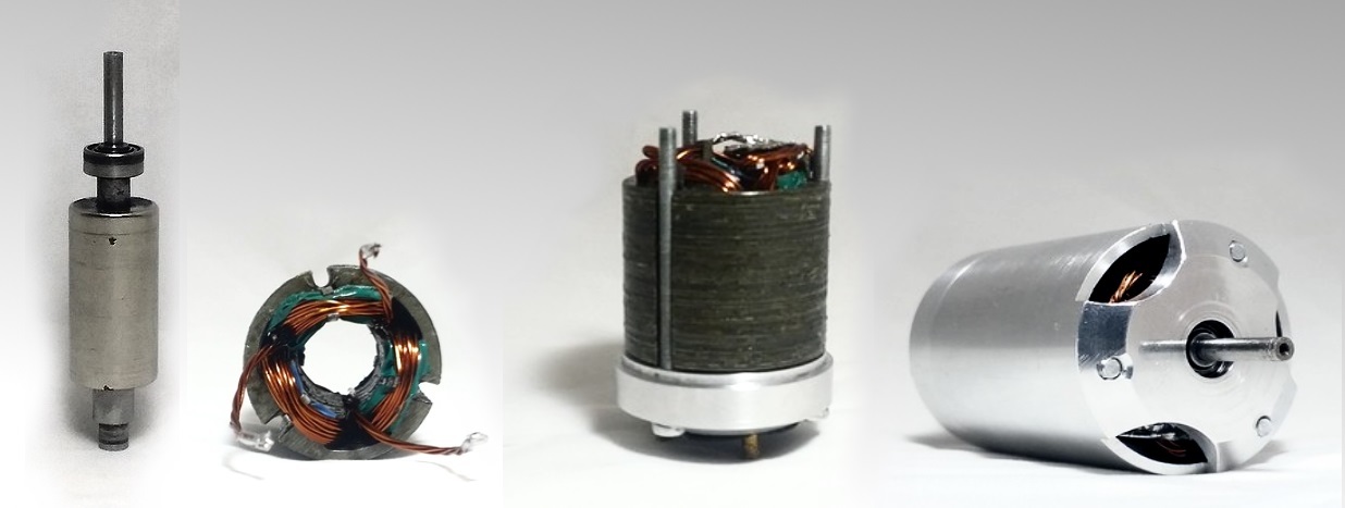
In the picture from left to right: rotor, stator, partial assembly of the motor, motor assembly
Electric motors appeared more than 150 years ago, but during this time their design has not undergone any special changes: a rotating rotor, stator copper windings, bearings. Over the years, there has been only a reduction in the weight of electric motors, an increase in efficiency, and also in the accuracy of speed control.
Today, thanks to the development of modern electronics and the emergence of powerful magnets based on rare earth metals, it is possible to create as powerful as ever and at the same time compact and lightweight “ Brushless ” electric motors. At the same time, due to the simplicity of their design, they are the most reliable electric motors ever created. About the creation of such a motor and will be discussed in this article.
')
In “Brushless Motor” there is no “Brush” element that is familiar to everyone when disassembling power tools, whose role is to transfer current to the winding of the rotating rotor. In brushless motors, the current is applied to the windings of a non-moving stator, which, by creating a magnetic field alternately at its individual poles, spins the rotor, on which the magnets are fixed.
The first such motor was printed by us to a 3D printer as an experiment. Instead of special plates made of electrical steel, for the rotor body and stator core, on which the copper coil was wound, we used ordinary plastic. Neodymium magnets of rectangular section were fixed on the rotor. Naturally, such a motor was not capable of delivering maximum power. However, this was enough for the motor to spin up to 20k rpm, after which the plastic could not stand it and the motor rotor broke, and the magnets were scattered around. This experiment encouraged us to create a full-fledged motor.
Having learned the opinion of fans of radio-controlled models, we chose a motor for racing cars of the “540” size as the most demanded one. This motor has dimensions of 54mm in length and 36mm in diameter.
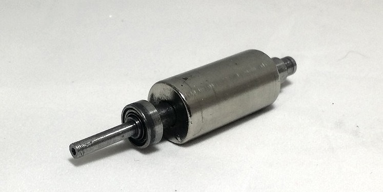
The rotor of the new engine we made from a single neodymium magnet in the shape of a cylinder. The epoxy magnet is glued to a shaft turned from tool steel at a pilot plant.
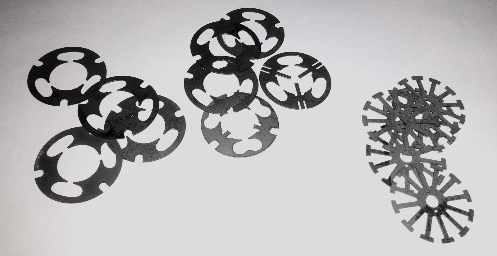
We cut out the stator with a laser from a set of plates of transformer steel 0.5 mm thick. Each plate was then carefully varnished, and then a ready-made stator was glued together from about 50 plates. Varnish plates were coated to avoid a short circuit between them and to eliminate the energy loss on the Foucault currents that could occur in the stator.
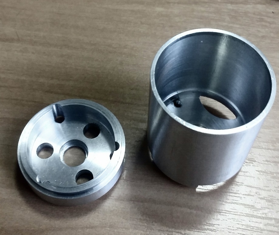
The motor housing was made of two aluminum parts in the form of a container. The stator fits snugly into the aluminum case and fits well against the walls. This design provides good cooling of the motor.
To achieve maximum performance of its developments, it is necessary to conduct an adequate assessment and accurate measurement of performance. For this we have designed and assembled a special dyno.
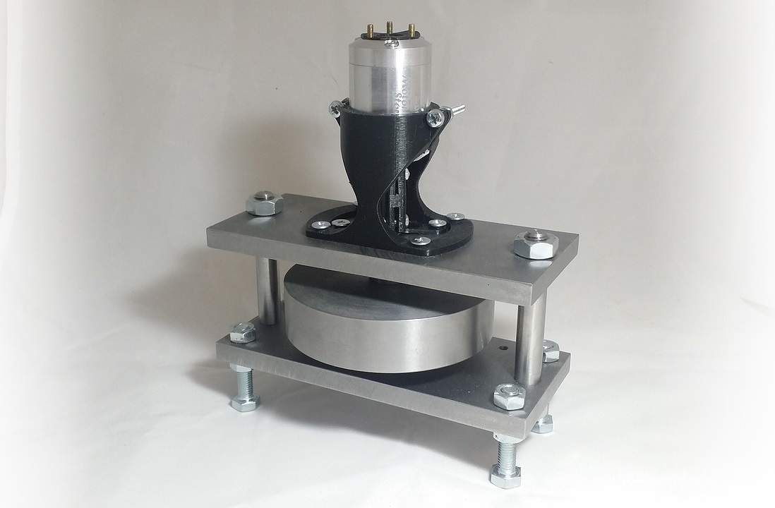
The main element of the stand is a heavy load in the form of a washer. During the measurements, the motor spins the load and the angular velocity and acceleration are calculated output power and torque of the motor.
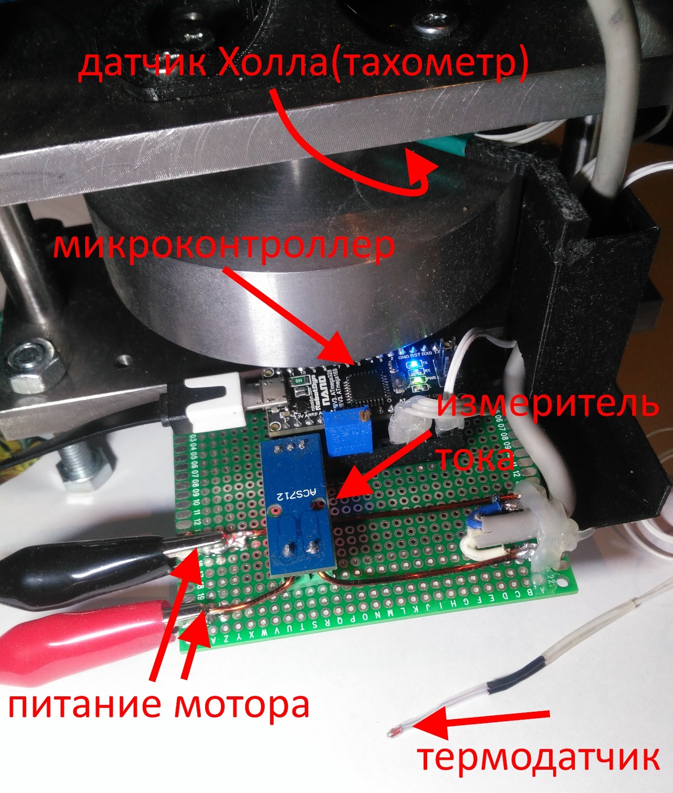
To measure the speed of rotation of the load, a pair of magnets on the shaft and a magnetic digital sensor A3144 based on the hall effect are used. Of course, it would be possible to measure revolutions by impulses directly from the motor windings, since this motor is synchronous. However, the sensor version is more reliable and it will work even at very low revs, at which the pulses will be unreadable.
In addition to speed, our stand is able to measure several more important parameters:
To collect all the parameters from the sensors and transfer them to a computer, the AVR mega series microcontroller on the Arduino nano board is used. The microcontroller communicates with the computer via the COM port. To process the readings, a special program was written that records, averages and demonstrates the measurement results.
As a result, our stand is able to measure at any time the following characteristics of the motor:
Video demonstrating the work of the stand:
To test the stand performance, we first tested it on a regular collector motor R540-6022. The parameters for this motor are known little enough, but this was enough to evaluate the measurement results, which turned out to be quite close to the factory ones.
Then our motor was tested. Naturally, he was able to show better efficiency (65% versus 45%) and, at the same time, a greater moment (1200 vs. 250 g per cm) than an ordinary motor. Temperature measurement also gave quite good results, during testing the motor did not heat up above 80 degrees.
But at the moment the measurements are not final yet. We were not able to measure the motor in the full rev range due to the limited power supply. We also have to compare our motor with similar motors of competitors and test it “in battle” by putting it on a racing radio-controlled car and perform at competitions.
In the picture from left to right: rotor, stator, partial assembly of the motor, motor assembly
Introduction
Electric motors appeared more than 150 years ago, but during this time their design has not undergone any special changes: a rotating rotor, stator copper windings, bearings. Over the years, there has been only a reduction in the weight of electric motors, an increase in efficiency, and also in the accuracy of speed control.
Today, thanks to the development of modern electronics and the emergence of powerful magnets based on rare earth metals, it is possible to create as powerful as ever and at the same time compact and lightweight “ Brushless ” electric motors. At the same time, due to the simplicity of their design, they are the most reliable electric motors ever created. About the creation of such a motor and will be discussed in this article.
')
Motor description
In “Brushless Motor” there is no “Brush” element that is familiar to everyone when disassembling power tools, whose role is to transfer current to the winding of the rotating rotor. In brushless motors, the current is applied to the windings of a non-moving stator, which, by creating a magnetic field alternately at its individual poles, spins the rotor, on which the magnets are fixed.
The first such motor was printed by us to a 3D printer as an experiment. Instead of special plates made of electrical steel, for the rotor body and stator core, on which the copper coil was wound, we used ordinary plastic. Neodymium magnets of rectangular section were fixed on the rotor. Naturally, such a motor was not capable of delivering maximum power. However, this was enough for the motor to spin up to 20k rpm, after which the plastic could not stand it and the motor rotor broke, and the magnets were scattered around. This experiment encouraged us to create a full-fledged motor.
First few prototypes
Having learned the opinion of fans of radio-controlled models, we chose a motor for racing cars of the “540” size as the most demanded one. This motor has dimensions of 54mm in length and 36mm in diameter.
The rotor of the new engine we made from a single neodymium magnet in the shape of a cylinder. The epoxy magnet is glued to a shaft turned from tool steel at a pilot plant.
We cut out the stator with a laser from a set of plates of transformer steel 0.5 mm thick. Each plate was then carefully varnished, and then a ready-made stator was glued together from about 50 plates. Varnish plates were coated to avoid a short circuit between them and to eliminate the energy loss on the Foucault currents that could occur in the stator.
The motor housing was made of two aluminum parts in the form of a container. The stator fits snugly into the aluminum case and fits well against the walls. This design provides good cooling of the motor.
Performance measurement
To achieve maximum performance of its developments, it is necessary to conduct an adequate assessment and accurate measurement of performance. For this we have designed and assembled a special dyno.
The main element of the stand is a heavy load in the form of a washer. During the measurements, the motor spins the load and the angular velocity and acceleration are calculated output power and torque of the motor.
To measure the speed of rotation of the load, a pair of magnets on the shaft and a magnetic digital sensor A3144 based on the hall effect are used. Of course, it would be possible to measure revolutions by impulses directly from the motor windings, since this motor is synchronous. However, the sensor version is more reliable and it will work even at very low revs, at which the pulses will be unreadable.
In addition to speed, our stand is able to measure several more important parameters:
- supply current (up to 30A) using a current sensor based on the hall effect ACS712;
- supply voltage. Measured directly through the microcontroller's ADC, through a voltage divider;
- temperature inside / outside the motor. Temperature is measured by semiconductor thermal resistance;
To collect all the parameters from the sensors and transfer them to a computer, the AVR mega series microcontroller on the Arduino nano board is used. The microcontroller communicates with the computer via the COM port. To process the readings, a special program was written that records, averages and demonstrates the measurement results.
As a result, our stand is able to measure at any time the following characteristics of the motor:
- current consumption;
- consumed voltage;
- power consumption;
- output power;
- shaft speed;
- shaft torque;
- Efficiency;
- power leaving in heat;
- temperature inside the motor.
Video demonstrating the work of the stand:
Test results
To test the stand performance, we first tested it on a regular collector motor R540-6022. The parameters for this motor are known little enough, but this was enough to evaluate the measurement results, which turned out to be quite close to the factory ones.
Then our motor was tested. Naturally, he was able to show better efficiency (65% versus 45%) and, at the same time, a greater moment (1200 vs. 250 g per cm) than an ordinary motor. Temperature measurement also gave quite good results, during testing the motor did not heat up above 80 degrees.
But at the moment the measurements are not final yet. We were not able to measure the motor in the full rev range due to the limited power supply. We also have to compare our motor with similar motors of competitors and test it “in battle” by putting it on a racing radio-controlled car and perform at competitions.
Source: https://habr.com/ru/post/400337/
All Articles