Electron microscope in the garage. Pump out
For those who are not yet aware of the project - you can read here .
It's time to use the metalworking machines for their intended purpose and grind everything you need for a microscope, and then try to connect the foreline pump and see what happens.
')
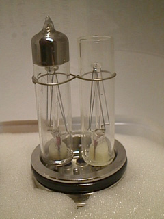 There is no standard vacuum port in this microscope. Two of his native gauge transducers worked according to the thermocouple method. In each of them there were two vacuum “lamps” with identical thermocouples inside. One lamp is sealed, with a “model” vacuum inside, and the second is open. Comparing the values of their resistance, it was possible to quantify the value of the vacuum. But the fact is that one of them was broken at all, and the second was glued in with a kind of glue, which over the years has decomposed back into a liquid state. And, of course, no measuring electronics remained for this. Therefore, the logical solution was to install more modern vacuum meters. Ideally, they are active, which give a signal ready for interpretation.
(thanks to KU - Resonant Research for the photo)
At first I didn’t come across such people, but the old Edwards Active Pirani Gauge PRL10, which turned out to be not Active at all, came across.
But they cost a penny, and have an expanded range of measurements due to a special elongated filament. I put them in place of two standard vacuum gauges JEOL, and for this it was required to make special adapters.
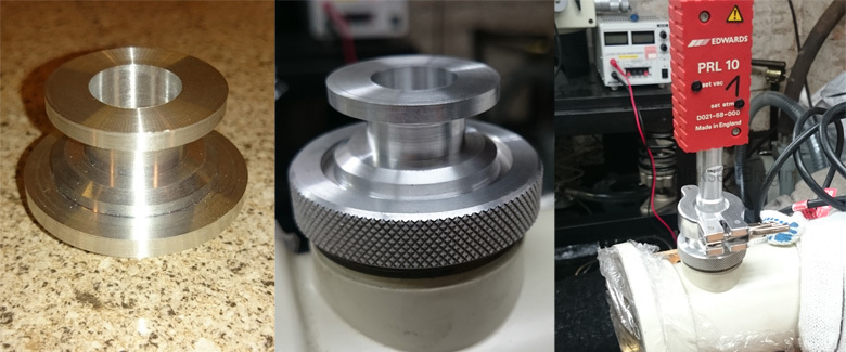
But recently I purchased a combined Pirani vacuum gauge + hot cathode . Next to the electron gun, the microscope has another port that is plugged with a native stub, and there even has a Viton seal.
I recorded the manufacturing history of the adapter for this vacuum meter.
The microscope was completed with two fore-vacuum pumps ( more on this ), but I simplified the design and decided to make a tee to connect the microscope to one powerful pump.
I already wrote that vacuum fittings are a special thing. You can not just take, cut the thread, wrap tape "FUM", and twist. All this will be missing. Therefore, the ideal option is to cut the tee from a single piece of metal. I decided to use duralumin D16T.
The pig is round. With great difficulty, you can fit a tee in it, but we will begin to learn turning and milling work immediately from the complex.
We use the technique experienced turners and clamp the disc with the displacement of one cam turning chuck. Surprisingly, everything is the same and you can pierce the two sides of the future tee under the thin hoses leading to the microscope. It is better to illustrate with a short video.
It is necessary to somehow make perpendicular input. We use the milling machine, holding the workpiece in the dividing head and cut through the inner hole.
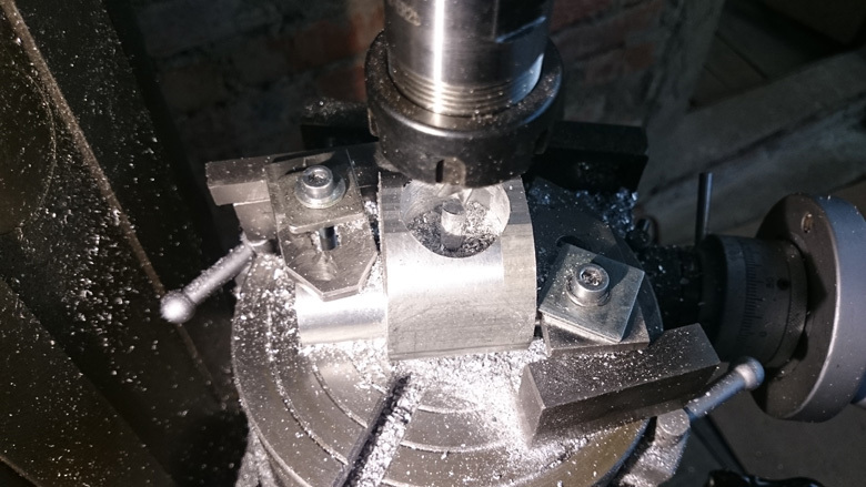
Done, but does not look very clean. Inside it is not important, but outside it must be done well and smoothly, otherwise the hose will loosely fit and allow air to flow through. A small lathe comes to the rescue: the cams of his chuck are small enough to take a tee to expand. We turn and mill the sides.
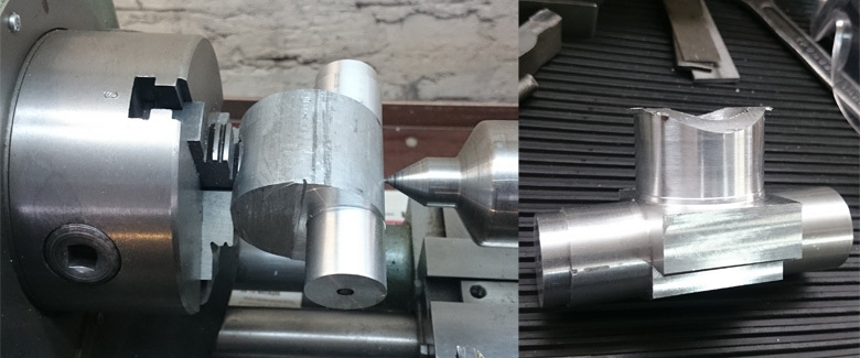
Gently clamp in a large lathe, and with a boring cutter, we bore on each side.
It remains to make a hole on the side of the connection of a large hose. For some reason I decided not to make a through hole, but to make a partition. Not sure that somehow improves the gas flow inside, but you can remove this partition at any time. Making holes on the drilling machine.
On this tee is ready, you can connect the microscope to the pump with hoses!
There is a large hole in the column for the secondary electron detector. I plan to place a detector there (depending on what can be found), but for now you just need to close it. Therefore, we sharpen a simple duralumin plug with a suitable rubber seal.

So it fits perfectly into the shape of the microscope. I didn’t even make a clamp, it’s pressed so well by vacuum.
I collected the very first option for testing: all openings are closed, the vacuum pump is connected to the three-phase network, it is constantly running, the air is pumped into the receiver, the valves are controlled from the toggle switches.
The pump on the video is not visible (but you can hear :)). Notice how the valve goes to the top left, and how the hoses are compressed-decompressed. We try!
The very first time I siphoned off without a working vacuum sensor, I simply plugged the holes, and therefore I tried the plug “to my touch”. The first results were quite good: I pumped out the column and left it for a month. Returning the first thing he tried to take off the cap - she was still holding tight. So, at least there shouldn't be a big big “hole”.
Then I connected a vacuum sensor, as well as a small inverter, which was very soon found with a friend. The fact is that in the microscope vacuum control unit there is a switch that synchronously turns on the foreline pump and closes the inlet valves. This is very convenient, so I decided to start controlling the booster pump on this switch. The inverter also provides a smooth start and braking of the pump electric motor, which should have a positive impact on its durability.
I collected all this, I launched it, but the forevacuum will not be reached. Somewhere passes, at the exit from the fornasos a small oily smoke constantly goes, and the pressure is about 1 Torr. Turn off - the vacuum keeps. Began to think how to find a leak without a leak detector. I took the degreaser in the sprayer, tried to spray near the seals, and followed the evacuation of the vacuum gauge (the logic was that the solvents penetrate the leakage faster and change the indications of the vacuum gauge).
Splashed-splashed, no result, the vacuum gauge does not change. I tried it with the pump on and off. Nothing.
The next idea is that fornasos can no longer. I don’t know what they did to him there, maybe all the records were erased there. To check, he quickly built an adapter, which mates a vacuum gauge with the pump inlet flange, and a screw for smooth air intake (if you simply disconnect the vacuum gauge with brute force, then the air flow inside the filament will collapse).
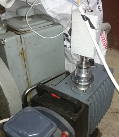
Turned on and almost instantly received a reading of the order of 10 ^ -2 Torr, which is normal for this pump and oil, which I poured into it. True, the screw for the inlet was essentially missing, and I had to adjust its position in order to approach 10 ^ -2 Torr, but this does not affect the essence of the experiment.
Then I thought logically, what could be the matter, and since at the hearing, I already began to distinguish how the pump sounds at different vacuum levels, then I tried to open the valve in the microscope and listen to whether it affects the sound. They did not affect, so the logic is what is missing the area connected by the hoses. And really! In the photo above, where the tee, I showed the final result, with clamps. The problem was that the hoses slightly bent on the tee when the pump was turned on, and began to pass.
He put the clamps, turned on and here it is - the whole column was evacuated to 10 ^ -2 Torr !
Step on the road to success. Let me remind you that the working pressure of the microscope is 10 ^ -5 Torr, which means that
the next series - we restore the diffusion pump and get a high vacuum .
Always happy to read all comments and suggestions. Waiting for your questions and preparing the material further :)
PS Correctly pump out like this:
It's time to use the metalworking machines for their intended purpose and grind everything you need for a microscope, and then try to connect the foreline pump and see what happens.
')
Adapters for vacuum gauges
There is no standard vacuum port in this microscope. Two of his native gauge transducers worked according to the thermocouple method. In each of them there were two vacuum “lamps” with identical thermocouples inside. One lamp is sealed, with a “model” vacuum inside, and the second is open. Comparing the values of their resistance, it was possible to quantify the value of the vacuum. But the fact is that one of them was broken at all, and the second was glued in with a kind of glue, which over the years has decomposed back into a liquid state. And, of course, no measuring electronics remained for this. Therefore, the logical solution was to install more modern vacuum meters. Ideally, they are active, which give a signal ready for interpretation.(thanks to KU - Resonant Research for the photo)
At first I didn’t come across such people, but the old Edwards Active Pirani Gauge PRL10, which turned out to be not Active at all, came across.
But they cost a penny, and have an expanded range of measurements due to a special elongated filament. I put them in place of two standard vacuum gauges JEOL, and for this it was required to make special adapters.
But recently I purchased a combined Pirani vacuum gauge + hot cathode . Next to the electron gun, the microscope has another port that is plugged with a native stub, and there even has a Viton seal.
I recorded the manufacturing history of the adapter for this vacuum meter.
Vacuum tee
The microscope was completed with two fore-vacuum pumps ( more on this ), but I simplified the design and decided to make a tee to connect the microscope to one powerful pump.
I already wrote that vacuum fittings are a special thing. You can not just take, cut the thread, wrap tape "FUM", and twist. All this will be missing. Therefore, the ideal option is to cut the tee from a single piece of metal. I decided to use duralumin D16T.
The pig is round. With great difficulty, you can fit a tee in it, but we will begin to learn turning and milling work immediately from the complex.
We use the technique experienced turners and clamp the disc with the displacement of one cam turning chuck. Surprisingly, everything is the same and you can pierce the two sides of the future tee under the thin hoses leading to the microscope. It is better to illustrate with a short video.
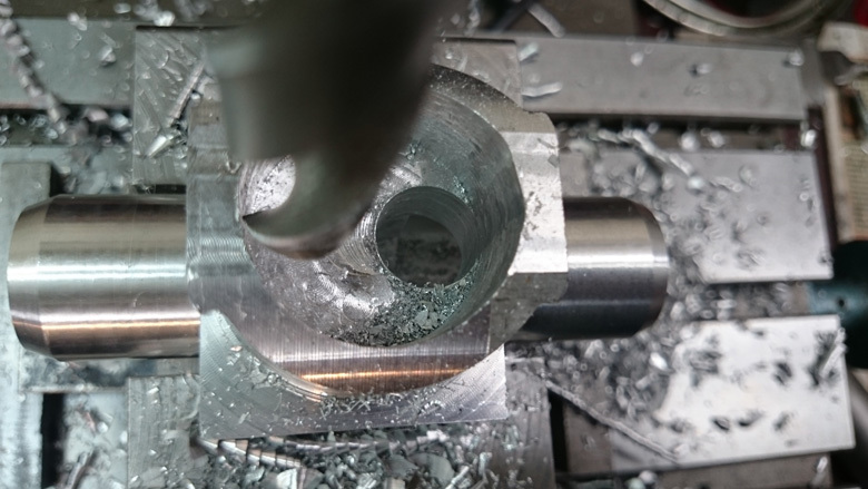
It is necessary to somehow make perpendicular input. We use the milling machine, holding the workpiece in the dividing head and cut through the inner hole.
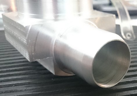
Done, but does not look very clean. Inside it is not important, but outside it must be done well and smoothly, otherwise the hose will loosely fit and allow air to flow through. A small lathe comes to the rescue: the cams of his chuck are small enough to take a tee to expand. We turn and mill the sides.
Gently clamp in a large lathe, and with a boring cutter, we bore on each side.
It remains to make a hole on the side of the connection of a large hose. For some reason I decided not to make a through hole, but to make a partition. Not sure that somehow improves the gas flow inside, but you can remove this partition at any time. Making holes on the drilling machine.
On this tee is ready, you can connect the microscope to the pump with hoses!
Electron Detector Plug
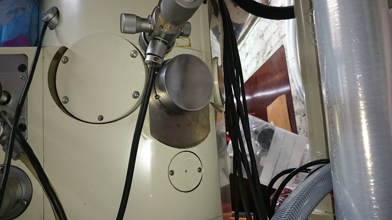
There is a large hole in the column for the secondary electron detector. I plan to place a detector there (depending on what can be found), but for now you just need to close it. Therefore, we sharpen a simple duralumin plug with a suitable rubber seal.
So it fits perfectly into the shape of the microscope. I didn’t even make a clamp, it’s pressed so well by vacuum.
Pumping the column to the forward vacuum
I collected the very first option for testing: all openings are closed, the vacuum pump is connected to the three-phase network, it is constantly running, the air is pumped into the receiver, the valves are controlled from the toggle switches.
The pump on the video is not visible (but you can hear :)). Notice how the valve goes to the top left, and how the hoses are compressed-decompressed. We try!
The very first time I siphoned off without a working vacuum sensor, I simply plugged the holes, and therefore I tried the plug “to my touch”. The first results were quite good: I pumped out the column and left it for a month. Returning the first thing he tried to take off the cap - she was still holding tight. So, at least there shouldn't be a big big “hole”.
Then I connected a vacuum sensor, as well as a small inverter, which was very soon found with a friend. The fact is that in the microscope vacuum control unit there is a switch that synchronously turns on the foreline pump and closes the inlet valves. This is very convenient, so I decided to start controlling the booster pump on this switch. The inverter also provides a smooth start and braking of the pump electric motor, which should have a positive impact on its durability.
I collected all this, I launched it, but the forevacuum will not be reached. Somewhere passes, at the exit from the fornasos a small oily smoke constantly goes, and the pressure is about 1 Torr. Turn off - the vacuum keeps. Began to think how to find a leak without a leak detector. I took the degreaser in the sprayer, tried to spray near the seals, and followed the evacuation of the vacuum gauge (the logic was that the solvents penetrate the leakage faster and change the indications of the vacuum gauge).
Splashed-splashed, no result, the vacuum gauge does not change. I tried it with the pump on and off. Nothing.
The next idea is that fornasos can no longer. I don’t know what they did to him there, maybe all the records were erased there. To check, he quickly built an adapter, which mates a vacuum gauge with the pump inlet flange, and a screw for smooth air intake (if you simply disconnect the vacuum gauge with brute force, then the air flow inside the filament will collapse).
Turned on and almost instantly received a reading of the order of 10 ^ -2 Torr, which is normal for this pump and oil, which I poured into it. True, the screw for the inlet was essentially missing, and I had to adjust its position in order to approach 10 ^ -2 Torr, but this does not affect the essence of the experiment.
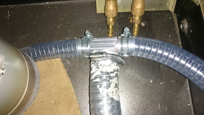
Then I thought logically, what could be the matter, and since at the hearing, I already began to distinguish how the pump sounds at different vacuum levels, then I tried to open the valve in the microscope and listen to whether it affects the sound. They did not affect, so the logic is what is missing the area connected by the hoses. And really! In the photo above, where the tee, I showed the final result, with clamps. The problem was that the hoses slightly bent on the tee when the pump was turned on, and began to pass.
He put the clamps, turned on and here it is - the whole column was evacuated to 10 ^ -2 Torr !
Step on the road to success. Let me remind you that the working pressure of the microscope is 10 ^ -5 Torr, which means that
the next series - we restore the diffusion pump and get a high vacuum .
Always happy to read all comments and suggestions. Waiting for your questions and preparing the material further :)
PS Correctly pump out like this:
Source: https://habr.com/ru/post/400035/
All Articles