Mapping and localization of a mobile robot in ROS without odometry using laser_scan_matcher
Good day readers! We have already touched upon the topic of localization and SLAM in an article about Hector SLAM . We will continue our acquaintance with the algorithms for building maps and localization in ROS. Today we will try to build a terrain map without a source of odometry, using only the Hokuyo URG-04LX-UG01 lidar and gmapping algorithm and localize the robot on the constructed map using the amcl algorithm. This will help us laser_scan_matcher . Who cares, I ask under the cat.
So, let's begin! For experiments we will use ROS Indigo, but you can use another version of ROS (Jade, Kinetic, Hydro). Package installation should be done in the same way (it is possible that some packages will not be available through apt-get only in Kinetic ROS).
The laser_scan_matcher package is a tool for incremental laser data recording, which is based on the Canonical Scan Matcher method, which you can read about here . Read about the package here . The package can be used without odometry data; it performs the odometry assessment itself.
')
Install the package:
Let's try the demo:
We will see something similar in rviz:
Here laser_scan_matcher is shown in action on the lidar data recorded in the bag file. Now try the package live. In order not to lose time, immediately try it with the gmapping algorithm. Create a package with the file my_gmapping_launch.launch to run gmapping:
Copy the following code into the my_gmapping_launch.launch file:
Here we run static_transform_publisher from the tf package to publish the transformation between the base_link → laser coordinate systems, the laser_scan_matcher and slam_gmapping nodes. The source code of the file can be downloaded from here . To use the Hokuyo lidar, we need to install the ROS hokuyo_node package:
Run the getID node from the hokuyo_node package to get information about the lidar:
An error may occur:
In this case, we need to add permissions for the / dev / ttyACM0 port:
Run getID from the hokuyo_node package again and get similar output:
Now run the hokuyo_node node:
Finally, let's launch our launch file my_gmapping_launch.launch:
Let's display the list of topics:
Among the topics we will see the following:
This way we get the odometry and position of the robot thanks to the laser_scan_matcher.
Add a LaserScan type display with a topic / scan to rviz as described in the article . We also add a display for the Map and for the TF transformation. Deploy the TF section and the Frames inside it, then check the points: odom, map, base_link. Let me remind you that these are the coordinate systems of odometry, map and robot, respectively. Do not forget to set the / map value for the Fixed frame field in the left panel Displays in the Global options section.
In rviz we will see a similar picture:
Then simply move the robot in space to build a complete map of the area. Use the map_saver utility from the map_server package to save the map:
Now let's try to localize the robot using the amcl algorithm. Create a file my_localize.launch inside our package with the following contents:
Here we are similar to the launcher for gmapping publish the transformation / laser → / base_link using the static_transform_publisher node, the hokuyo_node and laser_scan_matcher nodes. Then we run map_server to publish our constructed map, where in args we pass the path to the map in the yaml file. Finally, run the amcl node with parameters. You can read about amcl parameters on the official page of the algorithm .
The code for the launch file can also be downloaded from the github repository . Run our launch file:
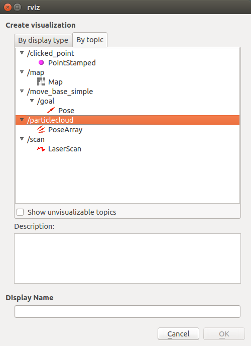
Now let's go to rviz. Set the map value for the Fixed frame in the Global options section. Let's display the list of topics:
New topics will appear in the list:
The amcl_pose topic corresponds to the position of the robot published by amcl.
Let's see the messages in the topic:
Get the position of the robot:
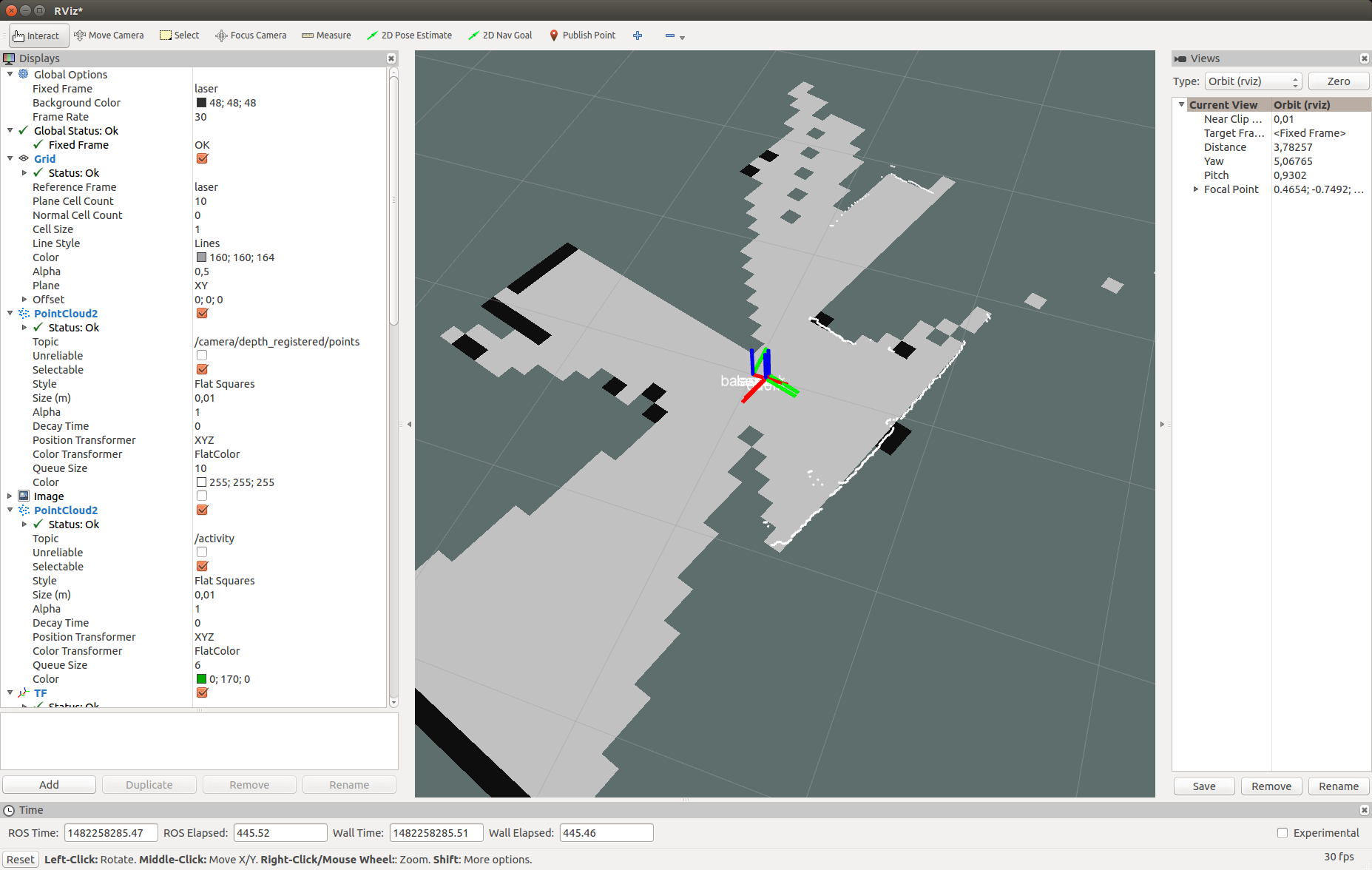
In rviz we get this picture:

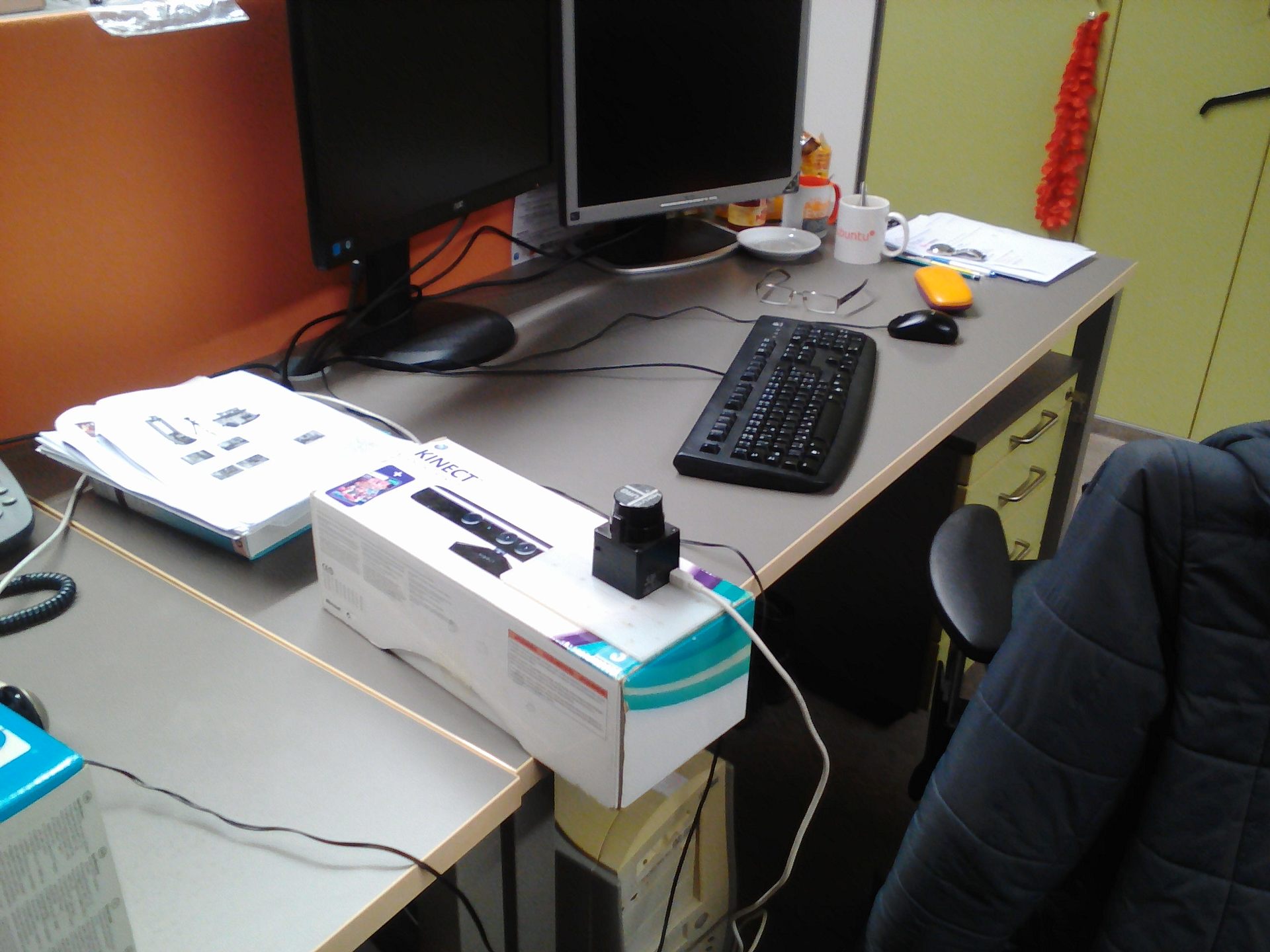
As you can see the scan points from the lidar partially coincide with the walls on the map. Here is what my installation looked like in reality:
Let's try to move the robot. The position of the robot and the point of view of the map should simultaneously change in the rviz window. After moving the robot, the position of the robot can be determined by the amcl algorithm not exactly. We need to adjust the position of the robot using the 2D Pose Estimate tool. To do this, click in the top toolbar in rviz on the 2D Pose Estimate button, click on the approximate point of the center of the robot coordinate system on the map in rviz (coordinate system base_link) and keep the mouse button held down. A green arrow will appear coming from the center of the robot:

Drag the arrow by changing its direction and trying to align the scan points from the lidar with black edges (walls) on the map. Having received the best combination let go of the mouse button.

We will receive such messages in the terminal where my_localize.launch is running:
In a short video you can see everything in action:
The topic / particlecloud presents data on the position of the robot as an uncertainty in the form of oriented positions (Pose) or the so-called cloud of particles. The message type is geometry_msgs / PoseArray.
Add a display by topic name / particlecloud :
In rviz, a cloud of particles appears in the form of a dense cluster of red arrows:

The thicker the cluster of particles, the higher the likelihood of the position of the robot in this position. About the 2D Pose estimate tool, particle cloud and other concepts in amcl can be found in the tutorial on the ros.org portal.
That's all! All the considered algorithms (gmapping and amcl) are part of a large stack of the Navigation stack in ROS, you can find a lot of information about it on the Internet. Today we tried the laser_scan_matcher tool, gmapping and amcl localization algorithms in action. Now you can easily start working on the localization and navigation of a mobile robot and create a fully autonomous robot capable of navigating in space without the need for manual control.
Subscribe to our group about ROS Vkontakte and stay informed about new articles and news about the ROS platform. I wish you all good luck in your experiments and see you soon!
PS: Happy New Year 2017!
Installing the laser_scan_matcher package
So, let's begin! For experiments we will use ROS Indigo, but you can use another version of ROS (Jade, Kinetic, Hydro). Package installation should be done in the same way (it is possible that some packages will not be available through apt-get only in Kinetic ROS).
The laser_scan_matcher package is a tool for incremental laser data recording, which is based on the Canonical Scan Matcher method, which you can read about here . Read about the package here . The package can be used without odometry data; it performs the odometry assessment itself.
')
Install the package:
sudo apt-get install ros-indigo-laser-scan-matcher Let's try the demo:
roscore roslaunch laser_scan_matcher demo.launch We will see something similar in rviz:
Here laser_scan_matcher is shown in action on the lidar data recorded in the bag file. Now try the package live. In order not to lose time, immediately try it with the gmapping algorithm. Create a package with the file my_gmapping_launch.launch to run gmapping:
cd ~/catkin_ws/src catkin_create_pkg my_laser_matcher cd src/my_laser_matcher mkdir launch vim launch/my_gmapping_launch.launch Copy the following code into the my_gmapping_launch.launch file:
Code my_gmapping_launch.launch
<?xml version="1.0"?> <launch> <node pkg="tf" type="static_transform_publisher" name="base_link_to_laser" args="0.0 0.0 0.0 0.0 0.0 0.0 /base_link /laser 40" /> <node pkg="laser_scan_matcher" type="laser_scan_matcher_node" name="laser_scan_matcher_node" output="screen"> <param name="fixed_frame" value = "odom"/> <param name="use_odom" value="true"/> <param name="publish_odom" value = "true"/> <param name="use_alpha_beta" value="true"/> <param name="max_iterations" value="10"/> </node> <node pkg="gmapping" type="slam_gmapping" name="slam_gmapping" output="screen"> <param name="map_udpate_interval" value="1.0"/> <param name="delta" value="0.02"/> </node> </launch> Here we run static_transform_publisher from the tf package to publish the transformation between the base_link → laser coordinate systems, the laser_scan_matcher and slam_gmapping nodes. The source code of the file can be downloaded from here . To use the Hokuyo lidar, we need to install the ROS hokuyo_node package:
sudo apt-get install ros-indigo-hokuyo-node Run the getID node from the hokuyo_node package to get information about the lidar:
rosrun hokuyo_node getID /dev/ttyACM0 An error may occur:
Error: Failed to open port. Permission denied. [ERROR] 1263843357.793873000: Exception thrown while opening Hokuyo. Failed to open port: /dev/ttyACM0. Permission denied (errno = 13). You probably don't have premission to open the port for reading and writing. (in hokuyo::laser::open) You may find further details at http://www.ros.org/wiki/hokuyo_node/Troubleshooting In this case, we need to add permissions for the / dev / ttyACM0 port:
sudo chmod a+rw /dev/ttyACM0 Run getID from the hokuyo_node package again and get similar output:
Device at /dev/ttyACM0 has ID H0906078 Now run the hokuyo_node node:
rosrun hokuyo_node hokuyo_node Finally, let's launch our launch file my_gmapping_launch.launch:
roslaunch my_laser_matcher my_gmapping_launch.launch rosrun rviz rviz Let's display the list of topics:
rostopic list Among the topics we will see the following:
/initialpose /move_base_simple/goal /odom /pose2D ... /imu/data This way we get the odometry and position of the robot thanks to the laser_scan_matcher.
Add a LaserScan type display with a topic / scan to rviz as described in the article . We also add a display for the Map and for the TF transformation. Deploy the TF section and the Frames inside it, then check the points: odom, map, base_link. Let me remind you that these are the coordinate systems of odometry, map and robot, respectively. Do not forget to set the / map value for the Fixed frame field in the left panel Displays in the Global options section.
In rviz we will see a similar picture:
Then simply move the robot in space to build a complete map of the area. Use the map_saver utility from the map_server package to save the map:
rosrun map_server map_saver Localization with amcl
Now let's try to localize the robot using the amcl algorithm. Create a file my_localize.launch inside our package with the following contents:
Code my_localize.launch
<launch> <param name="/use_sim_time" value="false"/> <node pkg="tf" type="static_transform_publisher" name="base_link_to_laser" args="0.0 0.0 0.0 0.0 0.0 0.0 /base_link /laser 40" /> <node name="hokuyo" pkg="hokuyo_node" type="hokuyo_node" respawn="false" output="screen"> <param name="calibrate_time" type="bool" value="false"/> <param name="port" type="string" value="/dev/ttyACM0"/> <param name="intensity" type="bool" value="false"/> </node> <node pkg="laser_scan_matcher" type="laser_scan_matcher_node" name="laser_scan_matcher_node" output="screen"> <param name="fixed_frame" value = "odom"/> <param name="use_alpha_beta" value="true"/> <param name="max_iterations" value="10"/> </node> <node name="map_server" pkg="map_server" type="map_server" args="/home/vladimir/catkin_ws/map.yaml"/> <node pkg="amcl" type="amcl" name="amcl" output="screen" > <!-- Publish scans from best pose at a max of 10 Hz --> <param name="odom_model_type" value="diff"/> <param name="odom_alpha5" value="0.1"/> <param name="transform_tolerance" value="0.2" /> <param name="gui_publish_rate" value="10.0"/> <param name="laser_max_beams" value="30"/> <param name="min_particles" value="500"/> <param name="max_particles" value="5000"/> <param name="kld_err" value="0.05"/> <param name="kld_z" value="0.99"/> <param name="odom_alpha1" value="0.2"/> <param name="odom_alpha2" value="0.2"/> <!-- translation std dev, m --> <param name="odom_alpha3" value="0.8"/> <param name="odom_alpha4" value="0.2"/> <param name="laser_z_hit" value="0.5"/> <param name="laser_z_short" value="0.05"/> <param name="laser_z_max" value="0.05"/> <param name="laser_z_rand" value="0.5"/> <param name="laser_sigma_hit" value="0.2"/> <param name="laser_lambda_short" value="0.1"/> <param name="laser_lambda_short" value="0.1"/> <param name="laser_model_type" value="likelihood_field"/> <!-- <param name="laser_model_type" value="beam"/> --> <param name="laser_likelihood_max_dist" value="2.0"/> <param name="update_min_d" value="0.2"/> <param name="update_min_a" value="0.5"/> <param name="odom_frame_id" value="odom"/> <param name="base_frame_id" type="str" value="base_link" /> <param name="global_frame_id" type="str" value="map" /> <param name="resample_interval" value="1"/> <param name="transform_tolerance" value="0.1"/> <param name="recovery_alpha_slow" value="0.0"/> <param name="recovery_alpha_fast" value="0.0"/> <param name="use_map_topic" value="true" /> <param name="first_map_only" value="true" /> </node> </launch> Here we are similar to the launcher for gmapping publish the transformation / laser → / base_link using the static_transform_publisher node, the hokuyo_node and laser_scan_matcher nodes. Then we run map_server to publish our constructed map, where in args we pass the path to the map in the yaml file. Finally, run the amcl node with parameters. You can read about amcl parameters on the official page of the algorithm .
The code for the launch file can also be downloaded from the github repository . Run our launch file:
roslaunch my_laser_matcher my_localize.launch Now let's go to rviz. Set the map value for the Fixed frame in the Global options section. Let's display the list of topics:
rostopic list New topics will appear in the list:
... /amcl/parameter_descriptions /amcl/parameter_updates /amcl_pose ... /map /map_metadata /map_updates ... /particlecloud The amcl_pose topic corresponds to the position of the robot published by amcl.
Let's see the messages in the topic:
rostopic echo /amcl_pose Get the position of the robot:
header: seq: 15 stamp: secs: 1482430591 nsecs: 39625000 frame_id: map pose: pose: position: x: 0.781399671581 y: 0.273353260585 z: 0.0 orientation: x: 0.0 y: 0.0 z: -0.636073020536 w: 0.771628869694 covariance: [0.2187289446708912, -0.010178711317316846, 0.0, 0.0, 0.0, 0.0, -0.010178711317316819, 0.23720047371620548, 0.0, 0.0, 0.0, 0.0, 0.0, 0.0, 0.0, 0.0, 0.0, 0.0, 0.0, 0.0, 0.0, 0.0, 0.0, 0.0, 0.0, 0.0, 0.0, 0.0, 0.0, 0.0, 0.0, 0.0, 0.0, 0.0, 0.0, 0.07106236846890918] --- In rviz we get this picture:
As you can see the scan points from the lidar partially coincide with the walls on the map. Here is what my installation looked like in reality:
Let's try to move the robot. The position of the robot and the point of view of the map should simultaneously change in the rviz window. After moving the robot, the position of the robot can be determined by the amcl algorithm not exactly. We need to adjust the position of the robot using the 2D Pose Estimate tool. To do this, click in the top toolbar in rviz on the 2D Pose Estimate button, click on the approximate point of the center of the robot coordinate system on the map in rviz (coordinate system base_link) and keep the mouse button held down. A green arrow will appear coming from the center of the robot:
Drag the arrow by changing its direction and trying to align the scan points from the lidar with black edges (walls) on the map. Having received the best combination let go of the mouse button.
We will receive such messages in the terminal where my_localize.launch is running:
[ INFO] [1482431993.717411186]: Setting pose (1482431993.717383): -0.413 -0.071 0.057 In a short video you can see everything in action:
The topic / particlecloud presents data on the position of the robot as an uncertainty in the form of oriented positions (Pose) or the so-called cloud of particles. The message type is geometry_msgs / PoseArray.
Add a display by topic name / particlecloud :
In rviz, a cloud of particles appears in the form of a dense cluster of red arrows:
The thicker the cluster of particles, the higher the likelihood of the position of the robot in this position. About the 2D Pose estimate tool, particle cloud and other concepts in amcl can be found in the tutorial on the ros.org portal.
That's all! All the considered algorithms (gmapping and amcl) are part of a large stack of the Navigation stack in ROS, you can find a lot of information about it on the Internet. Today we tried the laser_scan_matcher tool, gmapping and amcl localization algorithms in action. Now you can easily start working on the localization and navigation of a mobile robot and create a fully autonomous robot capable of navigating in space without the need for manual control.
Subscribe to our group about ROS Vkontakte and stay informed about new articles and news about the ROS platform. I wish you all good luck in your experiments and see you soon!
PS: Happy New Year 2017!
Source: https://habr.com/ru/post/399827/
All Articles