Simple charger for 2S batteries on STM32F030
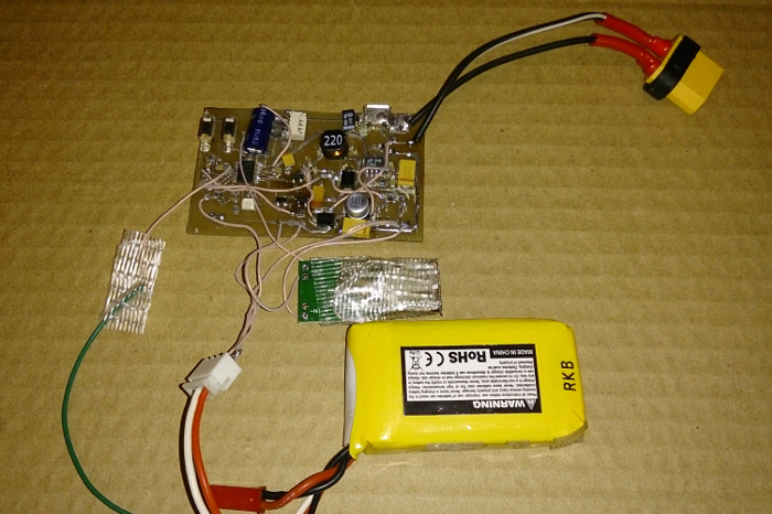
Some amount of 2S batteries of different capacity accumulated, which need to be recharged in “field conditions” from 12 volt batteries or USB. I decided to make a charger on a microcontroller, at the same time adding the function of recharging the phone from the same batteries (using the simplest step-down converter on MP1584EN). The scheme had to be redone in the process, so the view is not very presentable turned out.
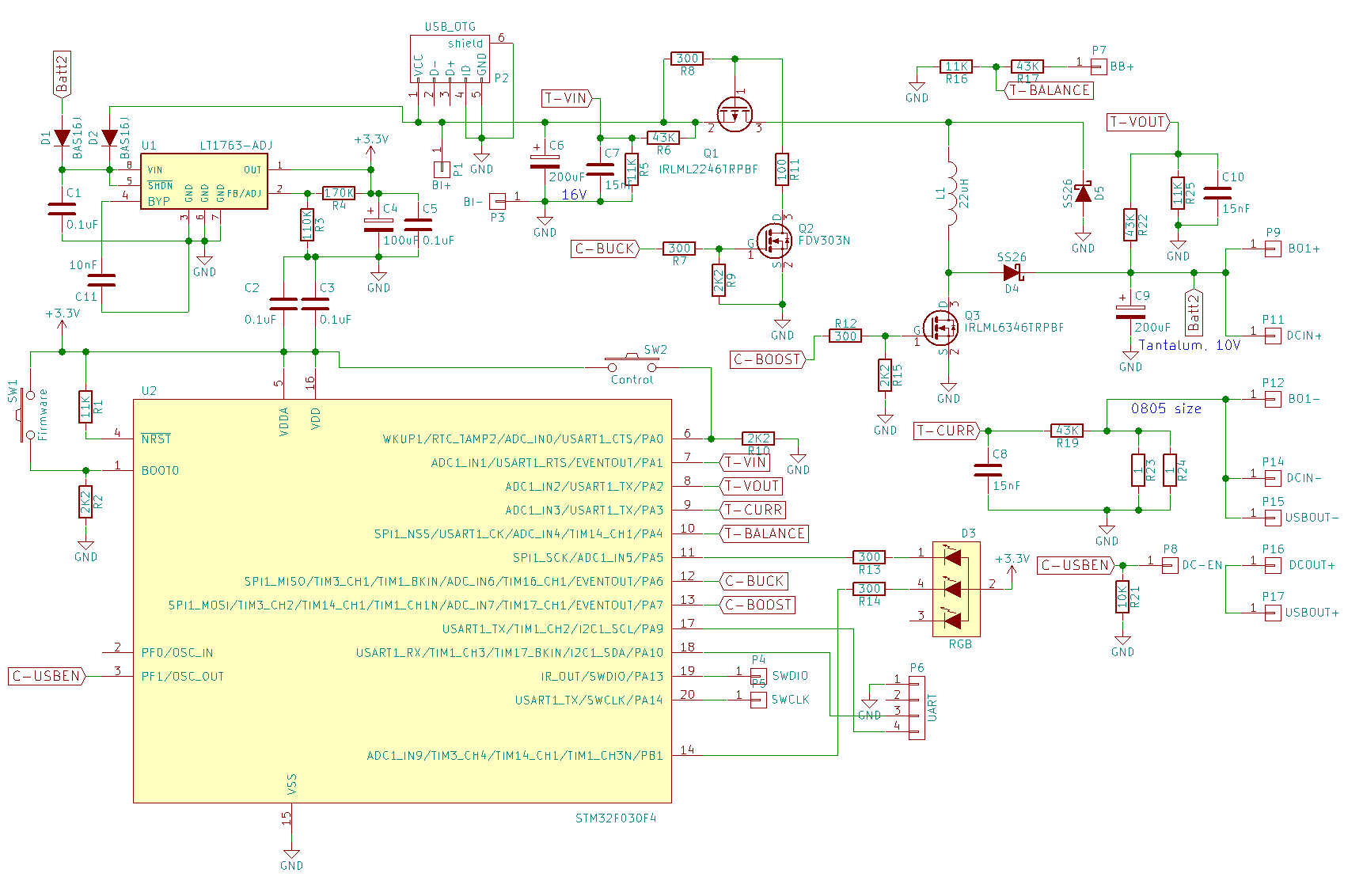
Functionally, the charger is the simplest combined buck-boost converter (500 kilohertz), with control of the charging current. All are controlled by the STM32F030F4P6, measuring the voltage on the battery, the balanced output (the junction point of two battery cells), the input and charging current, and also generating PWM pulses for key management. Indication - the simplest, using a two-color LED.
Scheme:
')
→ Code for firmware (project Eclipse + GNU ARM plugin)
Due to the simplicity, there is no battery cell balancing function (only control over recharging), so periodically it is necessary to balance the battery on a normal charger. You also can not connect to the input at the same time a 12 volt battery and USB power, since these inputs are trivially closed (you could probably plug a pair of diodes into the USB connector circuit and the 12 volt input, but somehow did not immediately think).
When a 12 volt source is connected, the buck converter works on Q1-L1-D5, and when power is applied to the USB connector, Q1 is simply constantly open, while the boost circuit is engaged on the Q3-L1-D4. The current is measured by a shunt at R23-R24 (two resistors in parallel are needed, since one resistor of size 0805 can overheat).
The output converter (for powering USB devices) is a ready-made Chinese module on the MP1584EN, only I had to solder to the second pin of this chip in order to be able to turn it off to avoid overdischarge.
Initially I used rather low-power transistors FDV303N / FDV304P as key ones, but quickly discovered that their resistance in the open state was too high and they periodically even independently soldered off the board due to overheating. I had to purchase and supply more powerful ones (IRLML2246 and IRLML6346).
Update: I printed a primitive case, it turned out 132x42x40 - I made a decent margin to fit batteries with long ends (in the photo, for example - 2.2 Ah * 35C battery).
Source: https://habr.com/ru/post/399719/
All Articles