Creating light hours
Hi, Geektimes! As a rule, when people talk about light hours, many people imagine devices that indicate the current time by means of a shadow. So it was in antiquity on a sundial, as it is in the modern world, in projects like the one that was on geektimes - Shadowplay .
I would like to tell about the design of the light clock, which is used to indicate the time, not the shadow, but the highlighted areas of the base surface, which is the dial. The idea was born in the process of the workshop, which was held on the basis of the magistracy of digital production at NITU "MISiS" under the guidance of the beautiful and unique Professor Jennifer Astwood University of Wisconsin-Stout. His goal was to create a lamp with LEDs. However, in addition to lighting, I wanted to realize the ability to display time. So the prototype was born (I think not the last) of my device.
Next will be a few photos and words about the stages of production, the concept of watches and the general impression of the work done.
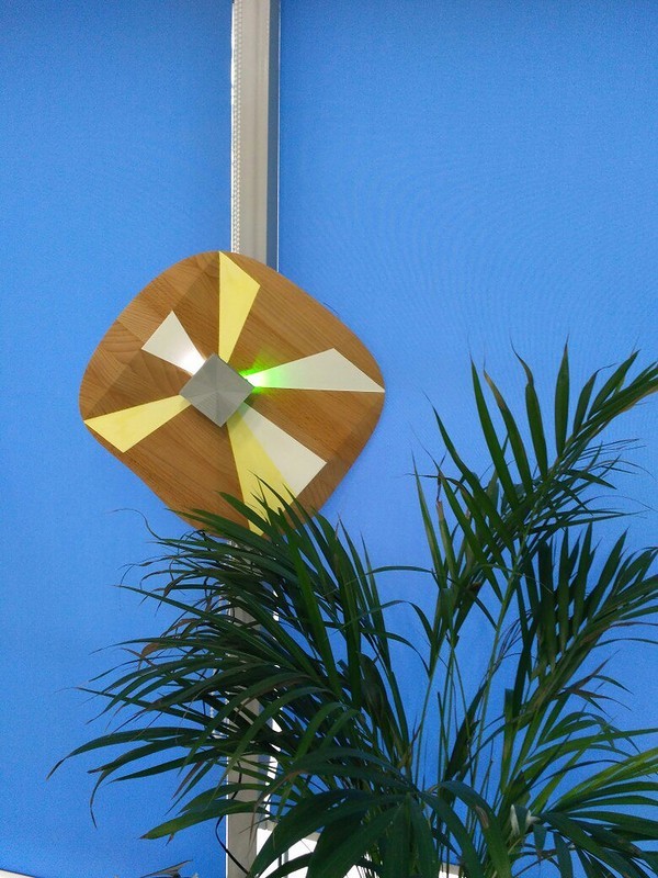
The first step was the development of the device design. I really like the texture of different types of wood - oak, beech, birch. The choice of material for the main dial was not painful for me. Benefit in any lerois sell good blanks of glued glued beech under the guise of steps for stairs. And the general geometry was dictated by the need to divide the surface into 12 elements. It was decided to mark the plane of the dial by placing a section of each hour at its own angle, thus forming a face. The angles of the faces indicate the specific hour. The triangle between the faces is a time segment multiple of 12. For a clear display of time, we had to use two colors - white shows minutes (in fact, a time segment is a multiple of 5 minutes), green - a clock (because of the highlight of the segment between the faces, we believe that the current hour is highlighted ). Thus, in the photo in the title of the topic, the time on the clock is somewhere 14.50 - 14.55.
')
It is worth noting that thanks to the Fablab MISiS it is possible to use a large number of milling and laser machines, as well as 3D printers.
Surface creation process:

The stage of rough milling on the portal three axial milling machine.

According to the resulting geometry, an LED board was developed in such a way that the light from the LEDs would fall on the bisector of the sector angle of time. LEDs of size 2835 were used, 2 pieces for each color and hour. The plate was engraved in the same way on a milling machine. For me, this was the first experience of wiring and production of boards, so it turned out to be not very high quality and accurate, but the board performs its function successfully in the future. The whole board is designed for smd installation, but I did not have access to solder paste and I collected the whole board with a soldering iron. By the end of the installation, I had already adapted to install the elements quite neatly, but this did not greatly improve the overall picture.

It remained to fix the board above the surface and limit the flow of light from the LEDs to illuminate only a specific time segment on the dial. The geometry of the board holder box repeated the face of the dial in a particular area. The box, the light deflector and the supporting axle were printed on the printer and subsequently glued together with cycacrine and hot melt, passing the cables from the board through the tube cavity.

The ignition process of the LEDs is implemented on the Arduino Mega board, while the minute LEDs have a soft ignition due to the PWM signal, and the hour lights turn on instantly.

The result of the assembly and settings are the clock presented in the title of the topic. Demonstration of their work is presented in the video. The operation mode is demo - accelerated to show how the light runs across the dial field. In real work, you have to wait 5 minutes to change the backlight.
Unfortunately, the thickness of the beech board was chosen from the available budget and did not allow for a deep relief (on this prototype the board was 20 mm, the relief was 13 mm deep) and, as a result, the segments did not read very well, which led to the need to color them by separating with color. Also, further modernization requires an approach to the direction of the light flux, in fact we have a very small area of illumination of the sector, moreover, the geometry of the shadow with the geometry of the dial is not very well observed. It is necessary to turn the LEDs from the horizontal plane and it is better to work out the deflector - it will be something to do during long winter evenings.
I would like to tell about the design of the light clock, which is used to indicate the time, not the shadow, but the highlighted areas of the base surface, which is the dial. The idea was born in the process of the workshop, which was held on the basis of the magistracy of digital production at NITU "MISiS" under the guidance of the beautiful and unique Professor Jennifer Astwood University of Wisconsin-Stout. His goal was to create a lamp with LEDs. However, in addition to lighting, I wanted to realize the ability to display time. So the prototype was born (I think not the last) of my device.
Next will be a few photos and words about the stages of production, the concept of watches and the general impression of the work done.
The first step was the development of the device design. I really like the texture of different types of wood - oak, beech, birch. The choice of material for the main dial was not painful for me. Benefit in any lerois sell good blanks of glued glued beech under the guise of steps for stairs. And the general geometry was dictated by the need to divide the surface into 12 elements. It was decided to mark the plane of the dial by placing a section of each hour at its own angle, thus forming a face. The angles of the faces indicate the specific hour. The triangle between the faces is a time segment multiple of 12. For a clear display of time, we had to use two colors - white shows minutes (in fact, a time segment is a multiple of 5 minutes), green - a clock (because of the highlight of the segment between the faces, we believe that the current hour is highlighted ). Thus, in the photo in the title of the topic, the time on the clock is somewhere 14.50 - 14.55.
')
It is worth noting that thanks to the Fablab MISiS it is possible to use a large number of milling and laser machines, as well as 3D printers.
Surface creation process:
The stage of rough milling on the portal three axial milling machine.
According to the resulting geometry, an LED board was developed in such a way that the light from the LEDs would fall on the bisector of the sector angle of time. LEDs of size 2835 were used, 2 pieces for each color and hour. The plate was engraved in the same way on a milling machine. For me, this was the first experience of wiring and production of boards, so it turned out to be not very high quality and accurate, but the board performs its function successfully in the future. The whole board is designed for smd installation, but I did not have access to solder paste and I collected the whole board with a soldering iron. By the end of the installation, I had already adapted to install the elements quite neatly, but this did not greatly improve the overall picture.
It remained to fix the board above the surface and limit the flow of light from the LEDs to illuminate only a specific time segment on the dial. The geometry of the board holder box repeated the face of the dial in a particular area. The box, the light deflector and the supporting axle were printed on the printer and subsequently glued together with cycacrine and hot melt, passing the cables from the board through the tube cavity.
The ignition process of the LEDs is implemented on the Arduino Mega board, while the minute LEDs have a soft ignition due to the PWM signal, and the hour lights turn on instantly.
int ledW[] = {3, 4, 5, 6, 7, 8, 9, 10, 11, 12, 13, 2}; int ledG[] = {22, 24, 26, 28, 30, 32, 34, 36, 38, 40, 42, 44}; void setup() { for (int i=0; i <= 11; i++){ pinMode(ledW[i], OUTPUT); pinMode(ledG[i], OUTPUT); } } void loop() { for (int j=0; j <= 11; j++){ digitalWrite(ledG[j], HIGH); for (int i=0; i <= 11; i++){ analogWrite(ledW[i], 67); delay(100); analogWrite(ledW[i], 130); delay(100); analogWrite(ledW[i], 200); delay(4800); analogWrite(ledW[i], 0); } digitalWrite(ledG[j], LOW); } } The result of the assembly and settings are the clock presented in the title of the topic. Demonstration of their work is presented in the video. The operation mode is demo - accelerated to show how the light runs across the dial field. In real work, you have to wait 5 minutes to change the backlight.
Unfortunately, the thickness of the beech board was chosen from the available budget and did not allow for a deep relief (on this prototype the board was 20 mm, the relief was 13 mm deep) and, as a result, the segments did not read very well, which led to the need to color them by separating with color. Also, further modernization requires an approach to the direction of the light flux, in fact we have a very small area of illumination of the sector, moreover, the geometry of the shadow with the geometry of the dial is not very well observed. It is necessary to turn the LEDs from the horizontal plane and it is better to work out the deflector - it will be something to do during long winter evenings.
Source: https://habr.com/ru/post/399491/
All Articles