Hakay CAN bus auto for voice control
A modern car is not only a means of transportation, but also an advanced gadget with multimedia functions and an electronic control system for units and a bunch of sensors. Many automakers offer the functions of traffic assistants, parking assistants, monitoring and controlling cars from the phone. This is possible due to the use of an auto CAN bus to which all systems are connected: engine, brake system, steering wheel, multimedia, climate, etc.
My car Skoda Octavia 2011 in. It does not offer management capabilities from the phone, so I decided to correct this shortcoming, and at the same time add the voice control function. As a gateway between the CAN bus and the phone, I use the Raspberry Pi with the CAN BUS shield and the TP-Link WiFi router. The protocol of communication units auto closed, and all my letters to provide documentation of the protocol Volkswagen refused. Therefore, the only way to learn how devices communicate in cars and learn how to control them is reverse engineering of the CAN bus VW protocol.
')
I acted in stages:
- CAN Shield Development for Raspberry Pi
- Installing software to work with CAN bus
- CAN bus connection
- Development of a sniffer and study of the CAN bus protocol
- Phone application development
- Voice control with Homekit and Siri
At the end of the voice control video window lifter.
CAN Shield Development for Raspberry Pi
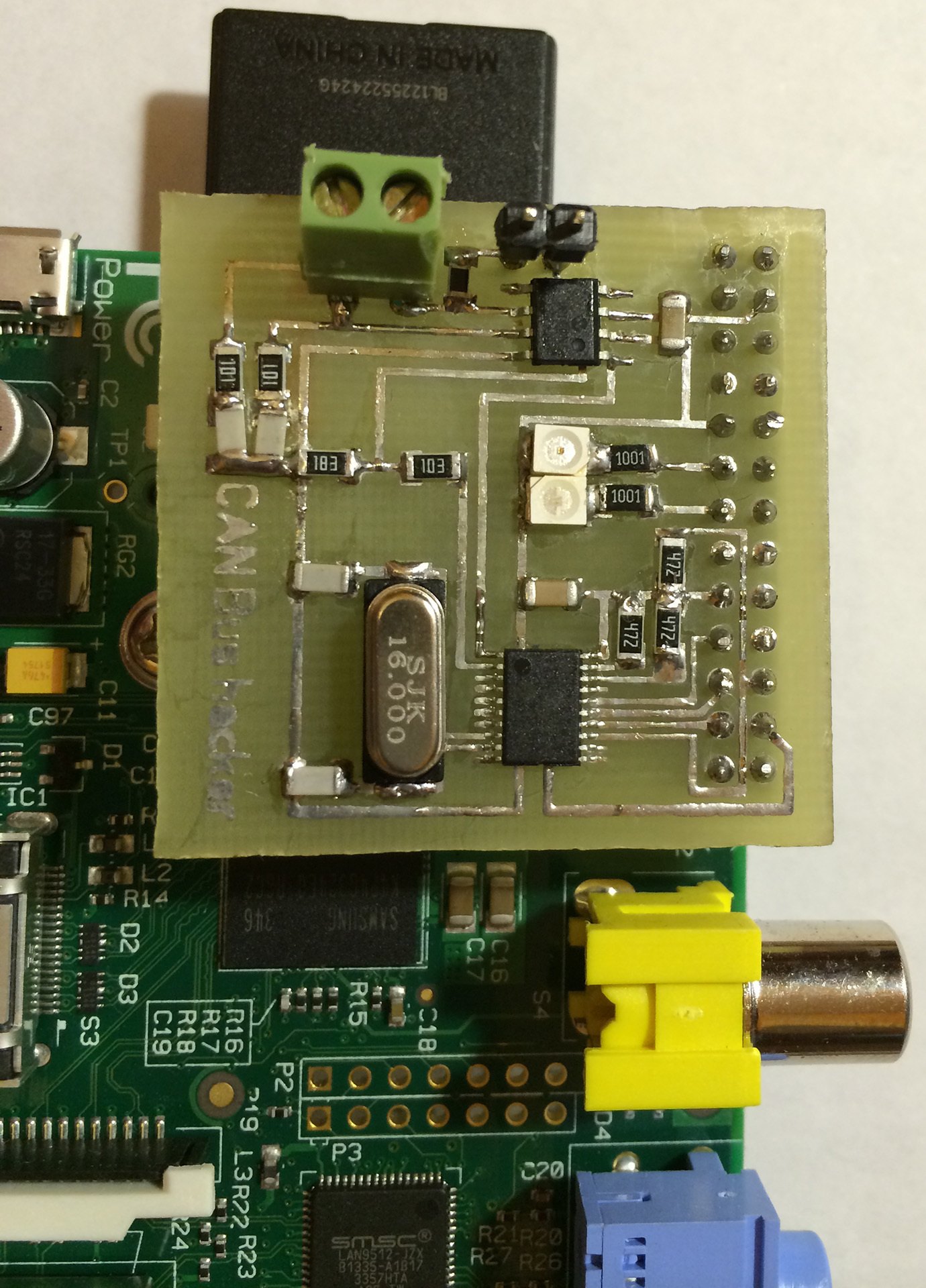
Schild took the scheme here lnxpps.de/rpie , in the same place the description of the conclusions, for communication with CAN 2 chips are used MCP2515 and MCP2551. 2 CAN-High and CAN-Low wires are connected to the shield. In SprintLayout 6, spread the board, who can use CANBoardRPi.lay (in the title photo, the prototype of the shield on the breadboard).

Installing software to work with CAN bus
On Raspbian 2-x a year ago, I needed to patch bcm2708.c to add support for CAN (maybe this is not needed now). To work with the CAN bus, you need to install the can-utils utilities package from github.com/linux-can/can-utils , then load the modules and raise the can interface:
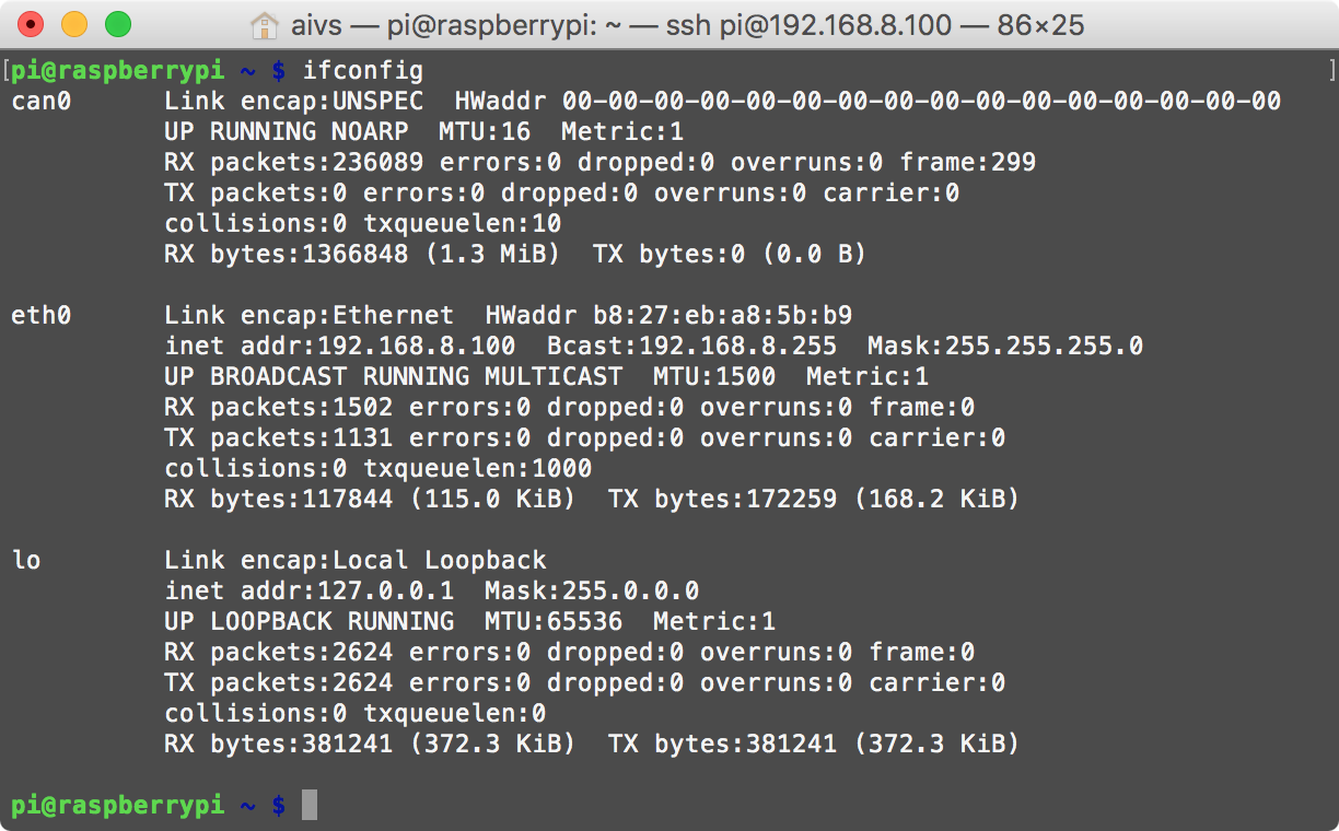
# initialize insmod spi-bcm2708 insmod can insmod can-dev insmod can-raw insmod can-bcm insmod mcp251x # Maerklin Gleisbox (60112 and 60113) uses 250000 # loopback mode for testing ip link set can0 type can bitrate 125000 loopback on ifconfig can0 up Check that the CAN interface has gone up with the ifconfig command:
Check that everything works by sending a command and receiving it.
In one terminal we listen:
root@raspberrypi ~ # candump any,0:0,#FFFFFFFF In another terminal we send:
root@raspberrypi ~ # cansend can0 123#deadbeef A more detailed installation process is described here lnxpps.de/rpie .
CAN bus connection
A little studying the open documentation on the CAN bus VW, I found out that I use 2 buses.
The CAN bus of the power unit , transmitting data at a speed of 500 kbit / s, connects all control units servicing this unit.
For example, the following devices can be connected to the CAN bus of a power unit:
- the engine control unit,
- ABS control unit,
- the control unit of the exchange rate stabilization system,
- gearbox control unit
- airbag control unit
- instrument cluster.
The CAN bus of the Comfort system and the information command system allows data transfer at a speed of 100 kbit / s between control units servicing these systems.
For example, to the CAN bus, the Comfort system and the information command system may be
The following devices are connected:
- Climatronic control unit or air conditioning system
- control units in the door of the car,
- Comfort control unit,
- control unit with display for radio and navigation system.
Having access to the first, you can control the movement (in my version on mechanics, at a minimum, you can control the cruise control), by gaining access to the second, you can control the radio, climate, central locking, power windows, headlights, etc.
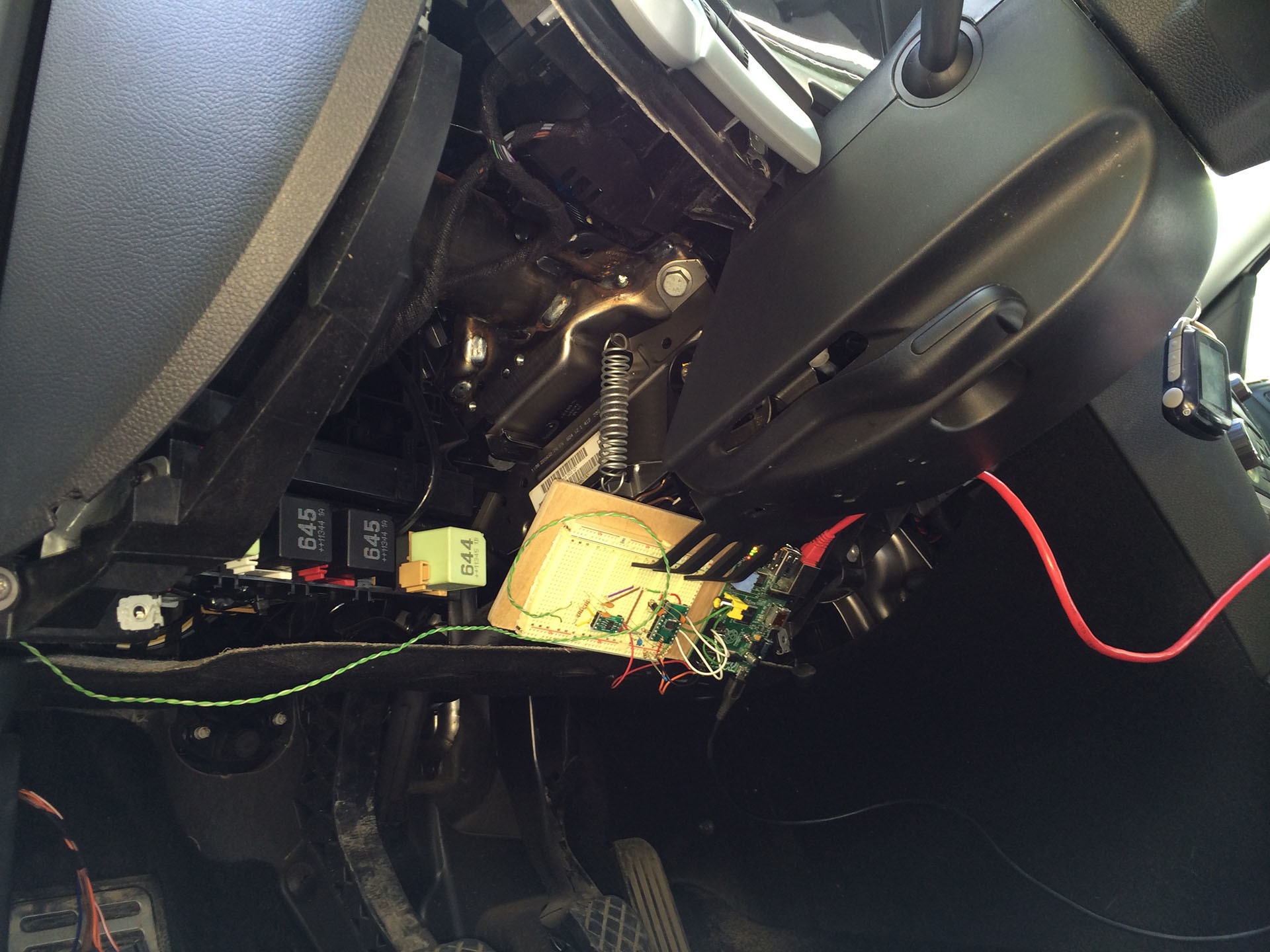
Both buses are connected through the gateway, which is located in the area under the steering wheel, the diagnostic OBD2 connector is also connected to the gateway, unfortunately you cannot listen to the traffic from both buses through the OBD2 connector, you can only send the command and request the status. I decided that I would work only with the Comfort bus and the most convenient place to connect to the bus was the connector in the driver's door.
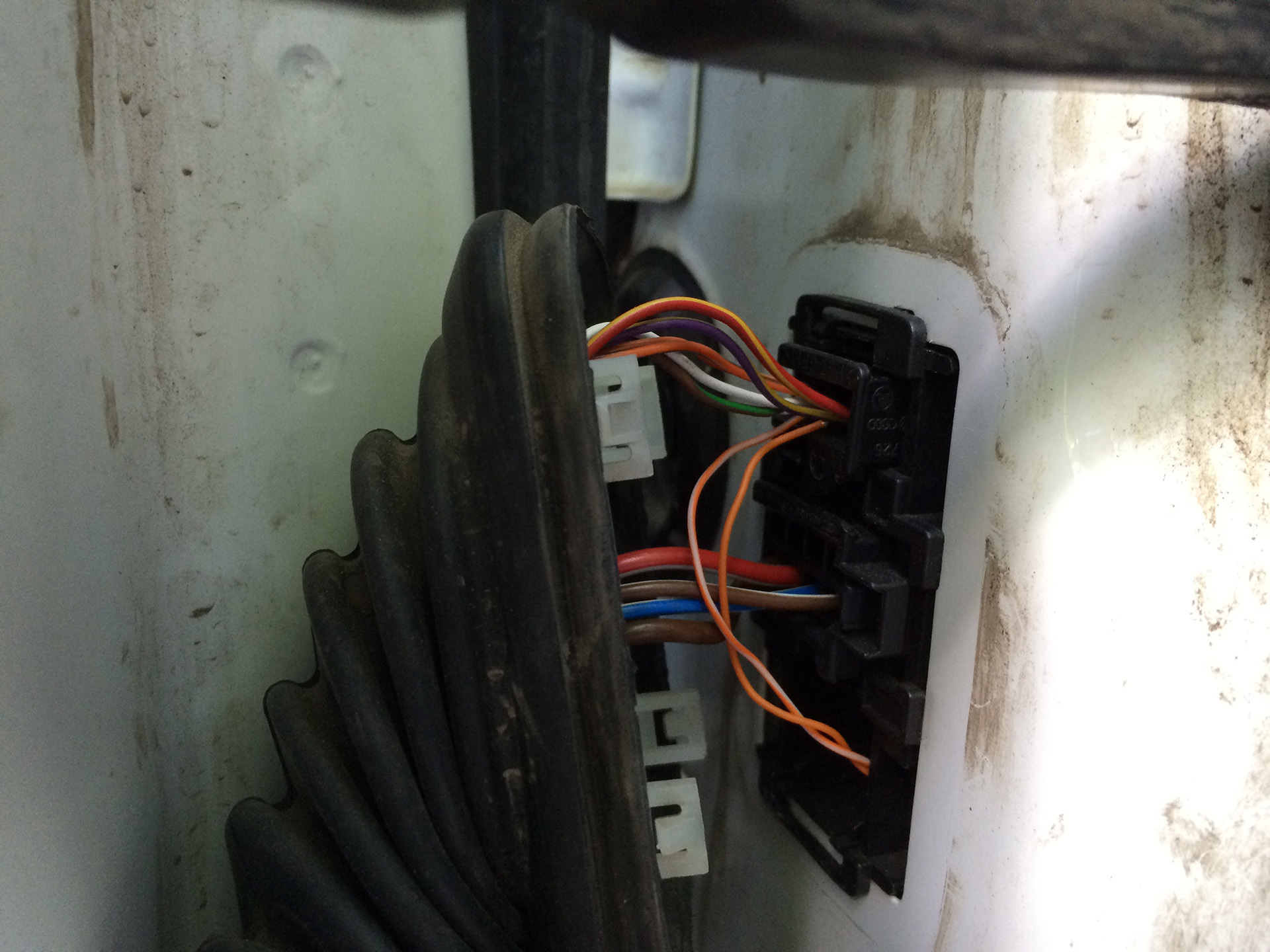
Now I can listen, everything that happens in the CAN bus "Comfort" and send commands.
Development of a sniffer and study of the CAN bus protocol
After I got access to listening to the CAN bus, I need to decipher who is transmitting what to whom. The format of the CAN packet is shown in the figure.
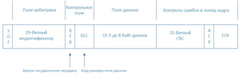
All utilities from the can-utils kit themselves can disassemble CAN packets and give only useful information, namely:
- Identifier
- Data length
- Data
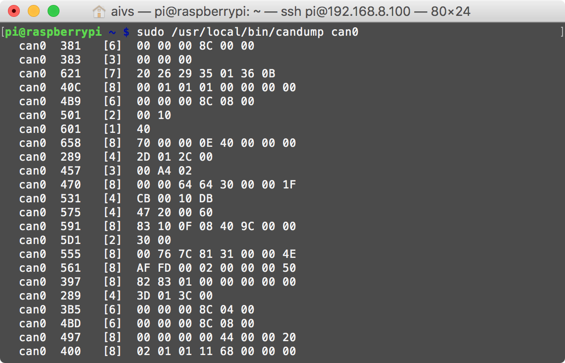
Data is transmitted in an unencrypted form, which facilitates the study of the protocol. On the Raspberry Pi, I wrote a small server that redirects data from the candump to TCP / IP in order to parse the data stream on the computer and beautifully show it.
For macOS, I wrote a simple application that for each device address adds a cell to the table and in this cell I can already see what data is changing.

I press the power window button, I found a cell in which the data is changing, then I determined which commands correspond to pressing down, pressing up, holding up, holding down.
You can check that the command is working by sending from the terminal, for example, the command to lift the left glass up:
cansend can0 181#0200 Commands that transmit devices over CAN bus in VAG cars (Skoda Octavia 2011), obtained by the reverse engineering method:
// Front Left Glass Up 181#0200 // Front Left Glass Down 181#0800 // Front Right Glass Up 181#2000 // Front Right Glass Down 181#8000 // Back Left Glass Up 181#0002 // Back Left Glass Down 181#0008 // Back Right Glass Up 181#0020 // Back Right Glass Down 181#0080 // Central Lock Open 291#09AA020000 // Central Lock Close 291#0955040000 // Update Light status of central lock ( / , , ) 291#0900000000 I was too lazy to study all the other devices, so on this list, only that which was interesting to me.
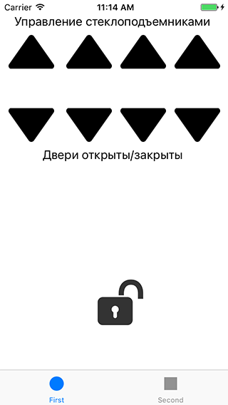
Phone application development
Using the commands I received, I wrote an iPhone application that opens / closes the windows and controls the central lock.
On the Raspberry Pi, I launched 2 small servers, the first one sends the data from the candump to TCP / IP, the second one takes the commands from the iPhone and sends them to the cansend.
Sources of the auto management application for iOS
// // FirstViewController.m // Car Control // // Created by Vitaliy Yurkin on 17.05.15. // Copyright (c) 2015 Vitaliy Yurkin. All rights reserved. // #import "FirstViewController.h" #import "DataConnection.h" #import "CommandConnection.h" @interface FirstViewController () <DataConnectionDelegate> @property (nonatomic, strong) DataConnection *dataConnection; @property (nonatomic, strong) CommandConnection *commandConnection; @property (weak, nonatomic) IBOutlet UILabel *Door_1; @property (weak, nonatomic) IBOutlet UILabel *Door_2; @property (weak, nonatomic) IBOutlet UILabel *Door_3; @property (weak, nonatomic) IBOutlet UILabel *Door_4; @property (weak, nonatomic) IBOutlet UIButton *CentralLock; - (IBAction)lockUnlock:(UIButton *)sender; @end @implementation FirstViewController - (void)viewDidLoad { self.dataConnection = [DataConnection new]; self.dataConnection.delegate = self; [self.dataConnection connectToCanBus]; self.commandConnection = [CommandConnection new]; [self.commandConnection connectToCanBus]; } - (void)didReceiveMemoryWarning { [super didReceiveMemoryWarning]; // Dispose of any resources that can be recreated. } - (void)doorStatusChanged:(char)value { /* 1 - Front Left Door 2 - Front Right Door 4 - Back Left Door 8 - Back Right Door 3 - Front Left&Right Door = 1 + 3 5 - Front& Back left Door = 1 + 4 */ // Front Left Door if (value & 1) { self.Door_1.backgroundColor = [UIColor yellowColor]; self.Door_1.text = @""; NSLog(@"1"); } else { self.Door_1.backgroundColor = [UIColor lightGrayColor]; self.Door_1.text = @""; } // Front Right Door if (value & 2) { self.Door_2.backgroundColor = [UIColor yellowColor]; self.Door_2.text = @""; NSLog(@"2"); } else { self.Door_2.backgroundColor = [UIColor lightGrayColor]; self.Door_2.text = @""; } // Back Left Door if (value & 4) { self.Door_3.backgroundColor = [UIColor yellowColor]; self.Door_3.text = @""; NSLog(@"4"); } else { self.Door_3.backgroundColor = [UIColor lightGrayColor]; self.Door_3.text = @""; } // Back Right Door if (value & 8) { self.Door_4.backgroundColor = [UIColor yellowColor]; self.Door_4.text = @""; NSLog(@"8"); } else { self.Door_4.backgroundColor = [UIColor lightGrayColor]; self.Door_4.text = @""; } } BOOL firstStatusChange = YES; BOOL lastStatus; -(void) centralLockStatusChanged:(BOOL)status { // At first status changes set lastStatus variable if (firstStatusChange) { firstStatusChange = NO; // Invert status, to pass the next test lastStatus = !status; } // Change Lock image only if status changed if (!(lastStatus == status)) { // Check status if (status) { [self.CentralLock setBackgroundImage:[UIImage imageNamed:@"lock_close"] forState:UIControlStateNormal]; } else { [self.CentralLock setBackgroundImage:[UIImage imageNamed:@"lock_open"] forState:UIControlStateNormal]; } lastStatus = status; } } // Front Left Glass - (IBAction)frontLeftUp:(UIButton *)sender { [self.commandConnection sendMessage:@"cansend can0 181#0200"]; } - (IBAction)frontLeftDown:(id)sender { [self.commandConnection sendMessage:@"cansend can0 181#0800"]; } // Front Right Glass - (IBAction)frontRightUp:(UIButton *)sender { [self.commandConnection sendMessage:@"cansend can0 181#2000"]; } - (IBAction)frontRightDown:(id)sender { [self.commandConnection sendMessage:@"cansend can0 181#8000"]; } // Back Left Glass - (IBAction)backLeftUp:(UIButton *)sender { [self.commandConnection sendMessage:@"cansend can0 181#0002"]; } - (IBAction)backLeftDown:(id)sender { [self.commandConnection sendMessage:@"cansend can0 181#0008"]; } // Back Right Glass - (IBAction)backRightUp:(UIButton *)sender { [self.commandConnection sendMessage:@"cansend can0 181#0020"]; } - (IBAction)backtRightDown:(id)sender { [self.commandConnection sendMessage:@"cansend can0 181#0080"]; } - (IBAction)lockUnlock:(UIButton *)sender { // If central lock closed if (lastStatus) { // Open [self.commandConnection sendMessage:@"cansend can0 291#09AA020000"]; int64_t delayInSeconds = 1; // 1 sec dispatch_time_t popTime = dispatch_time(DISPATCH_TIME_NOW, delayInSeconds * NSEC_PER_SEC); dispatch_after(popTime, dispatch_get_main_queue(), ^(void){ [self.commandConnection sendMessage:@"cansend can0 291#0900000000"]; }); } else { // Close [self.commandConnection sendMessage:@"cansend can0 291#0955040000"]; int64_t delayInSeconds = 1; // 1 sec dispatch_time_t popTime = dispatch_time(DISPATCH_TIME_NOW, delayInSeconds * NSEC_PER_SEC); dispatch_after(popTime, dispatch_get_main_queue(), ^(void){ [self.commandConnection sendMessage:@"cansend can0 291#0900000000"]; }); } } @end There is a way not to write your own application for a phone, but to use a ready-made from the world of smart homes, you just need to install the Z-Way automation system on the Raspberry Pi:
wget -q -O - razberry.z-wave.me/install | sudo bash After that we add our CAN devices to the Z-Way automation system
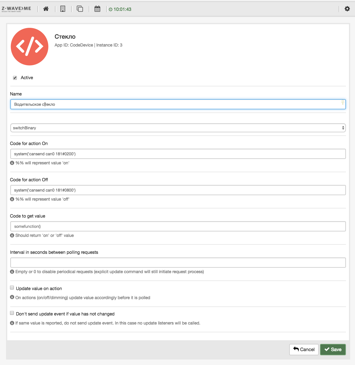
And control the window as an ordinary switch:

Mobile application for Z-Way: ZWay Home Control and ZWay Control.
Voice control with Homekit and Siri
In one of my articles, I described the installation process of Homebridge on the Raspberry Pi for voice control of the Z-Way home automation system . After installing Homebridge, you will be able to voice control with Siri. I am sure that for Android there are many applications that allow voice to send HTTP requests to control the Z-Way.
Video voice control windows attached.
Source: https://habr.com/ru/post/399043/
All Articles