Bike electrification kit development
Greetings to all who are interested in electronics! My name is Vasily Sukhoparov, I am the Technical Director of Eczo.bike. I want to talk about how we developed a bike electrification kit, which pitfalls we had to face and which engineering tricks to go. Ahead will be a little STM32 programming, circuits, subtleties of the design of power boards and a few words about the mechanical component of the KEV (Bike Electrification Kit).
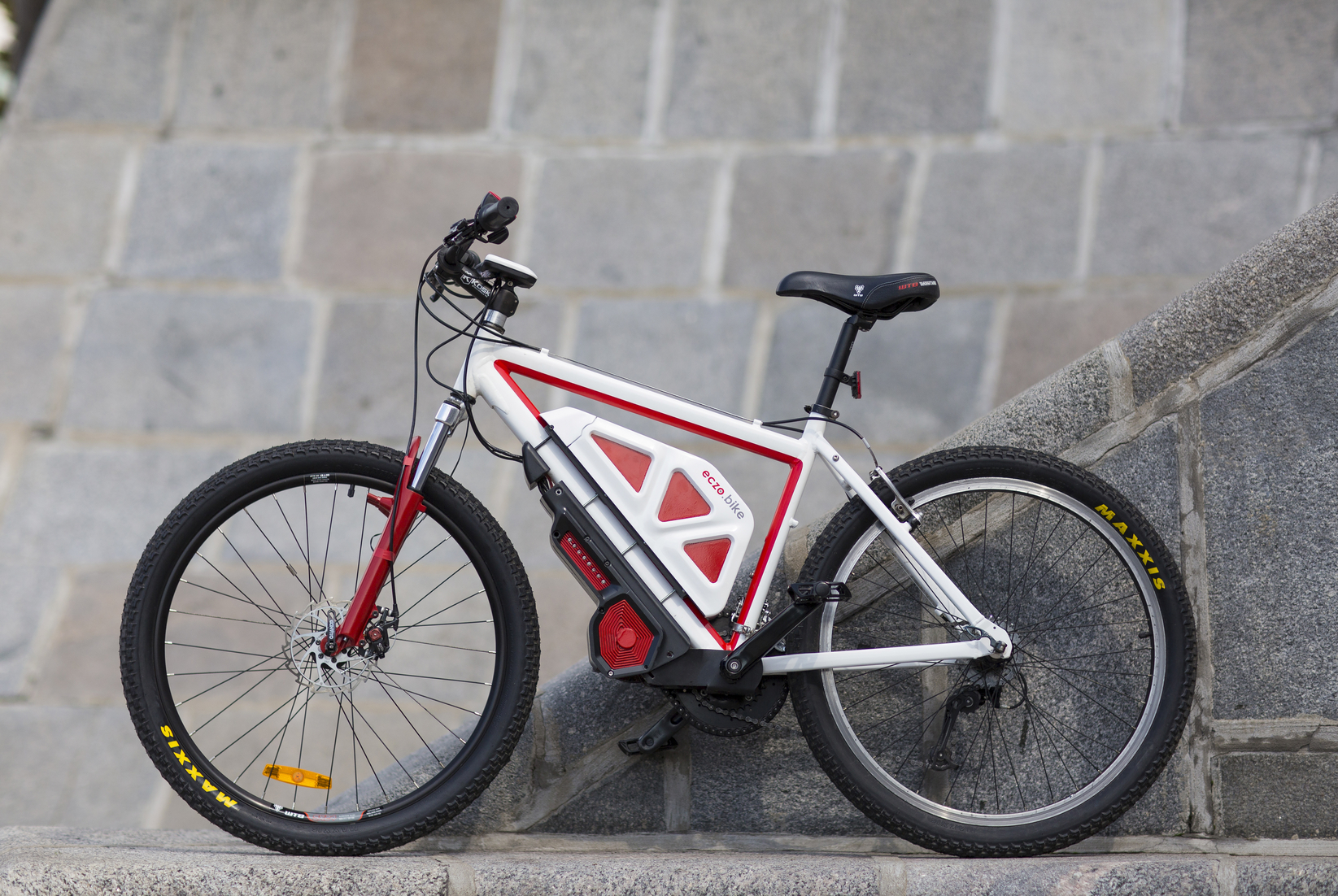
Electrification kit with a maximum power of 2600 W, on-board computer, tracker, and replaceable batteries.
Having experience of self-assembly of an electric bike in parts and a large number of stuffed cones in the process, led me to the understanding that at the moment there are no offers on the market that meet all my needs.
Every detail had to be customized, collective farm, invent something from scratch. You can not just take and plug on the bike electronics, like a new video card in the computer. There was no system Plug andPlay Ride.
')
Your own system could provide:
- modularity
- “user-friendly” interface
- the possibility of fine-tuning for themselves
- no need to solder connectors and in general the availability of knowledge in electronics
- low weight
All of the above is something that an ordinary user will have to encounter who wants to convert large Chinese components. With this approach, electro-bicycles will remain a lot of geeks and electronics engineers, unable to get into the masses.
Industrial solutions do not shine with special power (up to 1000W) and are often built into their own bicycle frames. In the home vacuum cleaner "horses" and then more :) About configurability and connection of additional features in general can not speak.
Gradually, starting from the development of the on-board computer in the basement of my house (literally) and ending with the inverter, battery management system and the entire kit as a whole, it came to understand how everything should line up to ensure maximum comfort from using this device. In this case, that the thing worked for the user, and not the user had to spend time to get it to work.
The prototype in the picture before the kata was assembled for the most part by manual labor, the boards were soldered right in the office, and immediately programmed. On the CNC, the cases of solid plastic bars were milled; the metal frame was made in production. The accumulators were assembled by their own labor, according to the technology a la Tesla, the basic component of which is an element in the form factor 18650, similar cells are found in most laptops. Yes, formally Tesla rides notebook batteries :-)

The on-board computer shows not only the battery voltage or the percentage of charge (which is sometimes uninformative), but also the consumption in Wh, the specific power consumption Wh / km, and the range, three main parameters that you want to know when you go somewhere far away and you need to plan a route. With an increase in speed, the air resistance also increases, moreover, in a progression, and it makes the main contribution to the energy consumption during movement. You can save less by pressing the sneaker on the floor, or twisting the pedals.
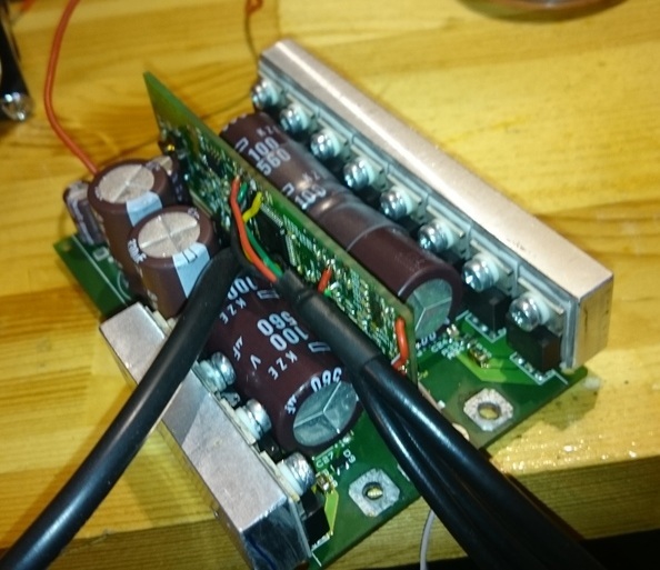
The inverter (in common - the controller) controls the motor, allows you to customize the driving modes, control of the load, speed, power, in general, allows you to configure the system fairly widely. It has built-in hardware short-circuit protection, temperature monitoring of transistors, a motor, support for a sensorless mode and the possibility of auto-detection of motor parameters. The brain of the inverter is STM32F405. By controlling all these parameters, it is possible to ensure high reliability from most cases that have arisen with me on Chinese electronics (whether it is overheating of the motor / controller, or burnout of the power switches due to the fact that the motor is locked, etc.).
Maximum TTX such a piece of iron - IN: 30 ~ 90V 150A, OUT: 200A. In KEV uses a simplified version of the controller with weaker characteristics.

BMS (Battery management system) - battery management system. Calculates the charge / discharge, controls the process of charging the elements and balances them, if necessary. The difference from conventional BMS is again in reliability, most often Chinese BMS with a flame burned out. You can see the voltage on each element of the battery, under load, you can monitor their internal resistance. The main battery defect is increased self-discharge and deterioration of the int. resistance, which can cause damage to the entire battery, if not noticed in time.
Built-in thermal control. Adding this module to the system allows you to use the battery as fully as possible without harming its health, for example, to reduce power when it is almost completely discharged or very cold / hot temperature, speeds up the charging process using its own balancing algorithm.

For the conversion of the bike was selected outboard motor, because only it allows you to get a good moment on the wheel and more power with less weight. This motor weighs 3kg. For comparison, the motor wheels are of two types: Direct drive - “direct drive” - there are 1000W or even more, but they weigh from 6 kg to 23 kg only per motor. Geared - gearbox - up to 500W weight from 2 kg, and literally a couple of motors 1000W to 4.5 kg. In the first case, it is necessary to put reinforced rims on the bike, and be sure to build up the iron at the point of attachment of the motor axis so that the frame does not roll. But no motor wheel in a similar weight category can get a moment of the order of 160 Nm at the rear wheel.
To ensure versatility in connection, a CAN bus with 13V on-board voltage and a separate battery bus with battery voltage was chosen.
The heart of the whole system is the controller that controls the motor. It converts DC voltage from battery to AC with frequency up to 1500 Hz. (PWM frequency is higher - up to 20 kHz) Control signals are received either directly or from the on-board computer (screen) via the CAN bus. It also has a Ubat converter. in 13V to ensure the operation of the modules.
The battery connects to the common network via BMS, as mentioned above, it monitors the battery to ensure its long service life. It also has a 13V converter for module operation.
The on-board computer is connected via a CAN bus with on-board voltage, it displays information that it receives from the modules, and can also record data on an SD card.
The tracker is also connected via CAN + 13V and has a small battery at its disposal to protect against bike theft when the main battery is missing.
The system supports connecting up to 4 batteries and controllers at the same time, for example, to control four-wheeled vehicles.
In the following articles I will discuss in more detail about the development of an onboard computer, a controller, a battery management system and how we collected batteries from the cells. If it is interesting, I will write a separate article about testing the drive on the dyno or how to measure the efficiency of the motor + controller bundle at home.
Electrification kit with a maximum power of 2600 W, on-board computer, tracker, and replaceable batteries.
What was all this for?
Having experience of self-assembly of an electric bike in parts and a large number of stuffed cones in the process, led me to the understanding that at the moment there are no offers on the market that meet all my needs.
Every detail had to be customized, collective farm, invent something from scratch. You can not just take and plug on the bike electronics, like a new video card in the computer. There was no system Plug and
')
Your own system could provide:
- modularity
- “user-friendly” interface
- the possibility of fine-tuning for themselves
- no need to solder connectors and in general the availability of knowledge in electronics
- low weight
All of the above is something that an ordinary user will have to encounter who wants to convert large Chinese components. With this approach, electro-bicycles will remain a lot of geeks and electronics engineers, unable to get into the masses.
Industrial solutions do not shine with special power (up to 1000W) and are often built into their own bicycle frames. In the home vacuum cleaner "horses" and then more :) About configurability and connection of additional features in general can not speak.
Gradually, starting from the development of the on-board computer in the basement of my house (literally) and ending with the inverter, battery management system and the entire kit as a whole, it came to understand how everything should line up to ensure maximum comfort from using this device. In this case, that the thing worked for the user, and not the user had to spend time to get it to work.
What is the result?
The prototype in the picture before the kata was assembled for the most part by manual labor, the boards were soldered right in the office, and immediately programmed. On the CNC, the cases of solid plastic bars were milled; the metal frame was made in production. The accumulators were assembled by their own labor, according to the technology a la Tesla, the basic component of which is an element in the form factor 18650, similar cells are found in most laptops. Yes, formally Tesla rides notebook batteries :-)
The on-board computer shows not only the battery voltage or the percentage of charge (which is sometimes uninformative), but also the consumption in Wh, the specific power consumption Wh / km, and the range, three main parameters that you want to know when you go somewhere far away and you need to plan a route. With an increase in speed, the air resistance also increases, moreover, in a progression, and it makes the main contribution to the energy consumption during movement. You can save less by pressing the sneaker on the floor, or twisting the pedals.
The inverter (in common - the controller) controls the motor, allows you to customize the driving modes, control of the load, speed, power, in general, allows you to configure the system fairly widely. It has built-in hardware short-circuit protection, temperature monitoring of transistors, a motor, support for a sensorless mode and the possibility of auto-detection of motor parameters. The brain of the inverter is STM32F405. By controlling all these parameters, it is possible to ensure high reliability from most cases that have arisen with me on Chinese electronics (whether it is overheating of the motor / controller, or burnout of the power switches due to the fact that the motor is locked, etc.).
Maximum TTX such a piece of iron - IN: 30 ~ 90V 150A, OUT: 200A. In KEV uses a simplified version of the controller with weaker characteristics.
BMS (Battery management system) - battery management system. Calculates the charge / discharge, controls the process of charging the elements and balances them, if necessary. The difference from conventional BMS is again in reliability, most often Chinese BMS with a flame burned out. You can see the voltage on each element of the battery, under load, you can monitor their internal resistance. The main battery defect is increased self-discharge and deterioration of the int. resistance, which can cause damage to the entire battery, if not noticed in time.
Built-in thermal control. Adding this module to the system allows you to use the battery as fully as possible without harming its health, for example, to reduce power when it is almost completely discharged or very cold / hot temperature, speeds up the charging process using its own balancing algorithm.
For the conversion of the bike was selected outboard motor, because only it allows you to get a good moment on the wheel and more power with less weight. This motor weighs 3kg. For comparison, the motor wheels are of two types: Direct drive - “direct drive” - there are 1000W or even more, but they weigh from 6 kg to 23 kg only per motor. Geared - gearbox - up to 500W weight from 2 kg, and literally a couple of motors 1000W to 4.5 kg. In the first case, it is necessary to put reinforced rims on the bike, and be sure to build up the iron at the point of attachment of the motor axis so that the frame does not roll. But no motor wheel in a similar weight category can get a moment of the order of 160 Nm at the rear wheel.
Characteristics of KEV
Peak power up to 2600 W electric
Maximum current of the motor 70A
Maximum battery current 50A
Battery Voltage 36.4 ~ 54.6V
Maximum charge current 1C (~ 1 hour)
CAN bus
DC-DC OUT: 13V 13W + 10W for modules
On-board computer with FSTN screen 240x128 2.8 "
Bluetooth 4.0 on BMS or in inverter
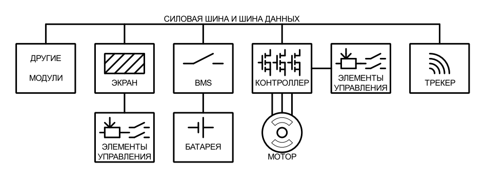
Device block diagram
To ensure versatility in connection, a CAN bus with 13V on-board voltage and a separate battery bus with battery voltage was chosen.
The heart of the whole system is the controller that controls the motor. It converts DC voltage from battery to AC with frequency up to 1500 Hz. (PWM frequency is higher - up to 20 kHz) Control signals are received either directly or from the on-board computer (screen) via the CAN bus. It also has a Ubat converter. in 13V to ensure the operation of the modules.
The battery connects to the common network via BMS, as mentioned above, it monitors the battery to ensure its long service life. It also has a 13V converter for module operation.
The on-board computer is connected via a CAN bus with on-board voltage, it displays information that it receives from the modules, and can also record data on an SD card.
The tracker is also connected via CAN + 13V and has a small battery at its disposal to protect against bike theft when the main battery is missing.
The system supports connecting up to 4 batteries and controllers at the same time, for example, to control four-wheeled vehicles.
In custody
In the following articles I will discuss in more detail about the development of an onboard computer, a controller, a battery management system and how we collected batteries from the cells. If it is interesting, I will write a separate article about testing the drive on the dyno or how to measure the efficiency of the motor + controller bundle at home.
Source: https://habr.com/ru/post/399029/
All Articles