We measure the power of a cell phone
The Internet is full of horror stories about the harm of mobile phones. These horror stories are not strongly supported by serious research, so we leave them on the authors' conscience. But the phone really emits some amount of power. Let's try to understand the problem. The first tests on the oscilloscope showed that the power changes very quickly over time, so the option of conditionally simultaneous measurement from different points will not work, and we will have to block the horn antenna with our own hands to collect the maximum radiated power.
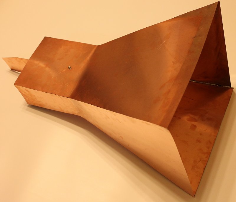
The result is presented on KDPV. The white balance was deliberately chosen wrong, because with the right balance, as we shall see, the surface of the foil is of a somewhat unpresentable color. But to embellish is not our method, so all the other pictures are “honest” - bitter is better, but true, than pleasant, but flattery (s).
First we need to measure the frequency range in which the phone communicates with the nearest towers, because The device itself was three-band: 900/1800/1900 MHz. Since we do not need coordination or total power to determine the range, we can use the simplest loop antenna with a diameter of about 300 mm inserted into the central contact of the input port of the spectrum analyzer. It is said - done, the range of 900 MHz. Not very nice, because the size of our future ward is the maximum possible. The wavelength is about 330 mm, half of it is 165 mm, which means, as textbooks teach us, it is reasonable to use a waveguide section of about 200x100 mm (the middle octave between the cut-off of the main mode and entering the waveguide of the second mode). It is reasonable, it is reasonable, but where to get this multi-kilogram monster? And what if we make it from foil fiberglass? The dimensions are small, the material is enough, stiffness, most likely, too. But what about the antenna itself? If you do it properly, you will have to open about a meter, and the length is even longer. Taking into account the doubts about the rigidity of such a structure and doubts about the sufficiency of materials, as a result, a volitional decision was made - to open up to 400 mm, and to limit the length of the structure to 600 mm. At the very least, it is worthwhile to pass primary tests, before making a structure comparable to a relic radiation detector.
')
The ruler and the marker are in the hands, later - the metal shears, as a result we have four nice blanks, from which we solder the horn antenna itself and the coaxial-waveguide junction in the form of a single product. At first glance, the surface of the foil was clean, so I decided to do without the skin and immediately began the process of soldering with the help of the usual POS-60 and rosin. We combine two blanks, fix an approximately right angle between them (I did without a square), grab it from one end, then at the bend, and finally at the second end. The textolite is thin, which means it is light, so this is already enough to prevent the structure from falling off under its own weight. Next, we completely solder the seam from the inside. But it was not there - on the first seam it took about half an hour, besides, the last two seams would have to be done under conditions of increasing claustrophobia from the assembled structure. Rejecting the reluctance to dirty clean pants flying with dust from the skin, I still cleaned the surface for soldering, after which I tinted all the common edges of the blanks. After this, the process of complete propaying of one seam with the control of the light propagation began to take a couple of minutes, and the implementation of the last two seams is not so much more complicated than the first. Outside closeup:

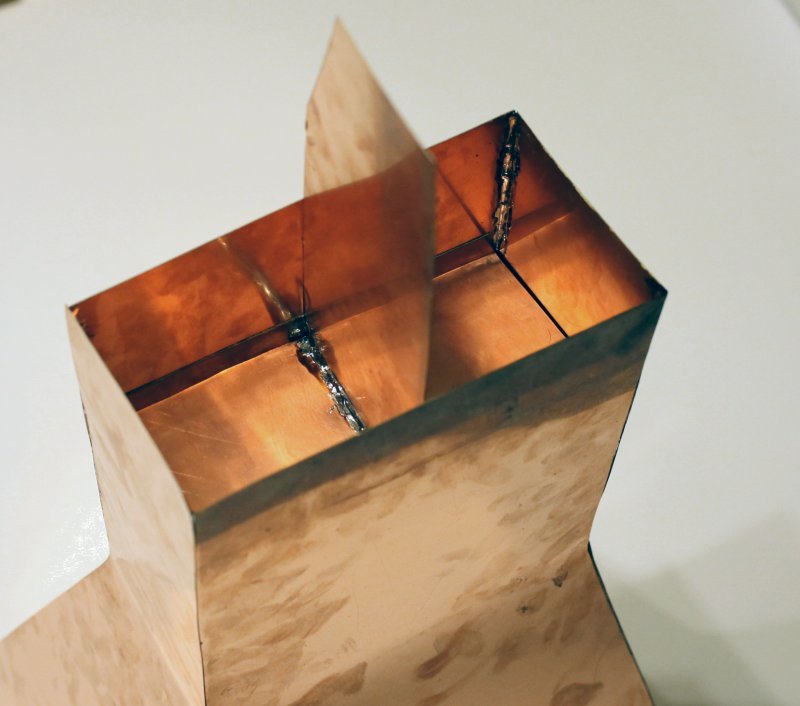
The seam looks in my opinion quite well, the waviness in a fraction of a millimeter, which is quite acceptable. Now we are making a short-circuiting piston from PCB scraps. To do this, bend the U-shaped billet, the central part of which is slightly less than the internal cross section of the waveguide part and solder the next piece to it, for which the piston can be pulled out if it is quiescent:
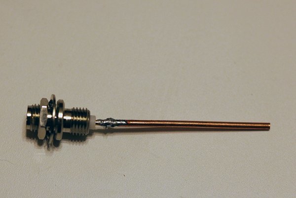
Solder the antenna with a length of less than half the short side of the waveguide to the SMA connector:
This is an unused curve option. Install it into the hole made in the middle of the long wall:

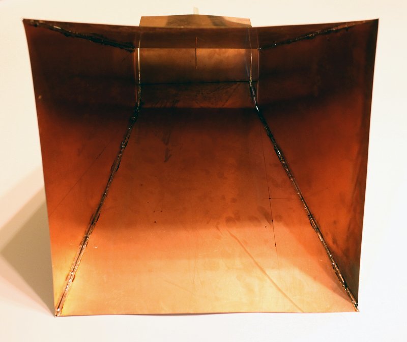
And we see the antenna from the front of the horn (you can see both the antenna and its reflection):
In principle, we are ready to measure with an oscilloscope, but for insurance, first of all, let's see what level of power we can encounter. The World Encyclopedia gives us the following data: the maximum radiated power of mobile phones of the standard GSM-1800 is 1 W, for the GSM-900 it is 2 W. These capacities are large enough, the coaxial detector will not work in quadratic mode. To reduce the power and transfer the detector closer to the correct mode, we set the attenuator to 15 dB (more, unfortunately, it was not found, it would be better for thirty-fives). Go to the tests on the oscilloscope.
We put the phone on a wooden chair, turn on dialing and put a horn with a connected detector on top of the phone. First, we make sure that the maximum amplitude of the received signal is reached exactly in the center of the horn while the phone is long (vertical) in parallel with the horn antenna, then adjust the position of the piston to the maximum signal. Now you can begin to remove the "meaningful" waveforms from the detector. None of the tests was able to achieve a signal amplitude of more than 200 mV. Unfortunately, this value is higher than the range of calibration available in our hands:
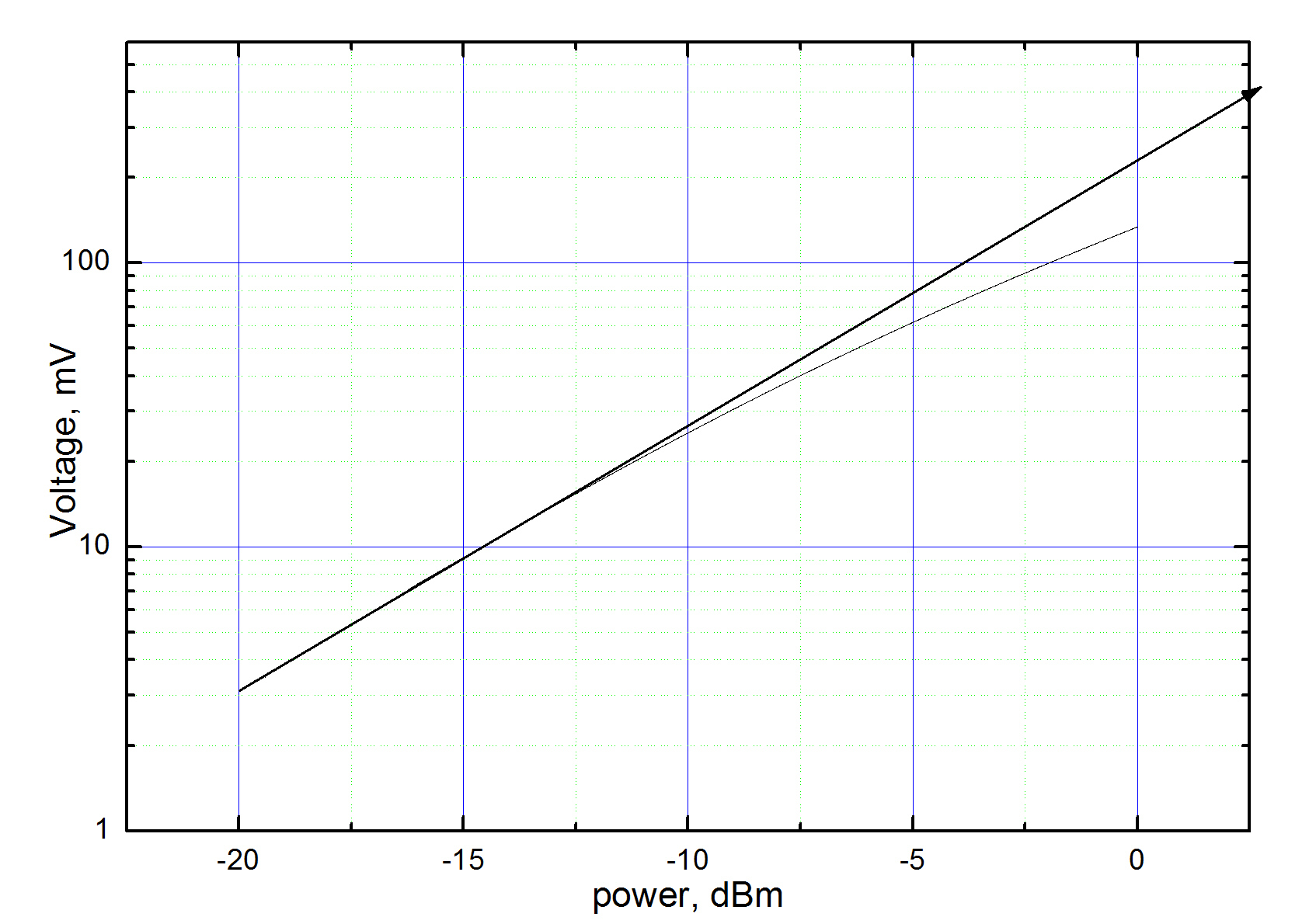
Nevertheless, it is possible to extrapolate the data to the right and obtain a power value of about +3 dBm (the decimal logarithm of the power divided by 1 mW). Add here 15 dB attenuator and 3 dB to the symmetrical radiation inside the antenna and in the opposite direction (check the phone's flipping). Total we get +21 dBm or 126 mW. The value, in my opinion, is quite reasonable. Unfortunately, attempts to force the phone to lose the signal of the base station and to increase the transmission power to the maximum were unsuccessful. For this, a screened room or a Faraday cage with a grid much shorter than the wavelength would be perfect, but nothing similar was found nearby. For some reason, I did not want to take out the roll of the chain-link netting and wrap it with it. Thus, no definitive answers were received, and I even thought not to publish the article. But, after some thought, I decided that a small addition of graphs would brighten up a DIY article.
In the picture below, there are two data sets - during an attempt to dial and during a conversation:
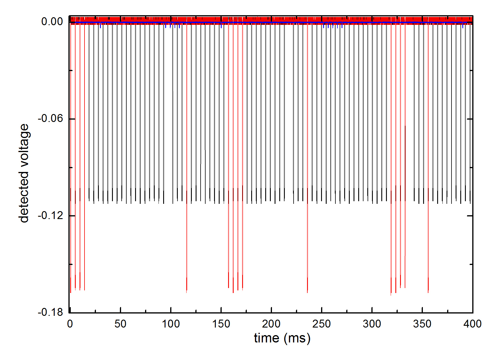
Strangely enough, but during the conversation (red curve) data is transferred even less. The same schedule details:
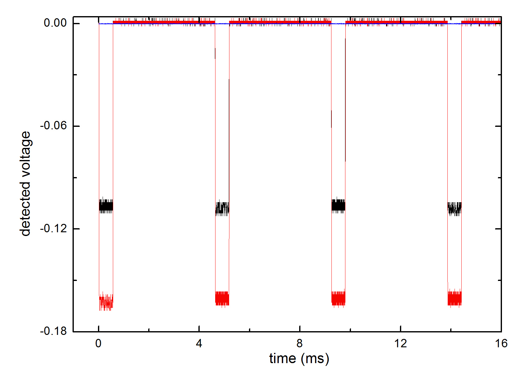
The frame duration approximately corresponds to the nominal value of 577 μs, the period also corresponds to the nominal value - eight frames. Some readers probably have a question - how can you transmit voice data at a frame rate (bits) of about 200 Hz (and in fact and below)? The fact is that for data transmission, not amplitude, but quadrature modulation is used. Without going into the wilds of this not the simplest object, I will say that one frame is not one bit, obtained using amplitude modulation, but a whole data packet, modulated not amplitude, but phase-wise (in fact, it is still trickier, but , beyond the scope of the article). Naturally, after simple detection, we see no traces of the phase. I note that the average power is less than the peak power eight times due to the intervals between the frames, and once again at five due to the sparsity of the transmission intervals.
To prove the linearity of the polarization of radiation, we remove the signal by turning the phone 90 degrees around the direction of the horn:
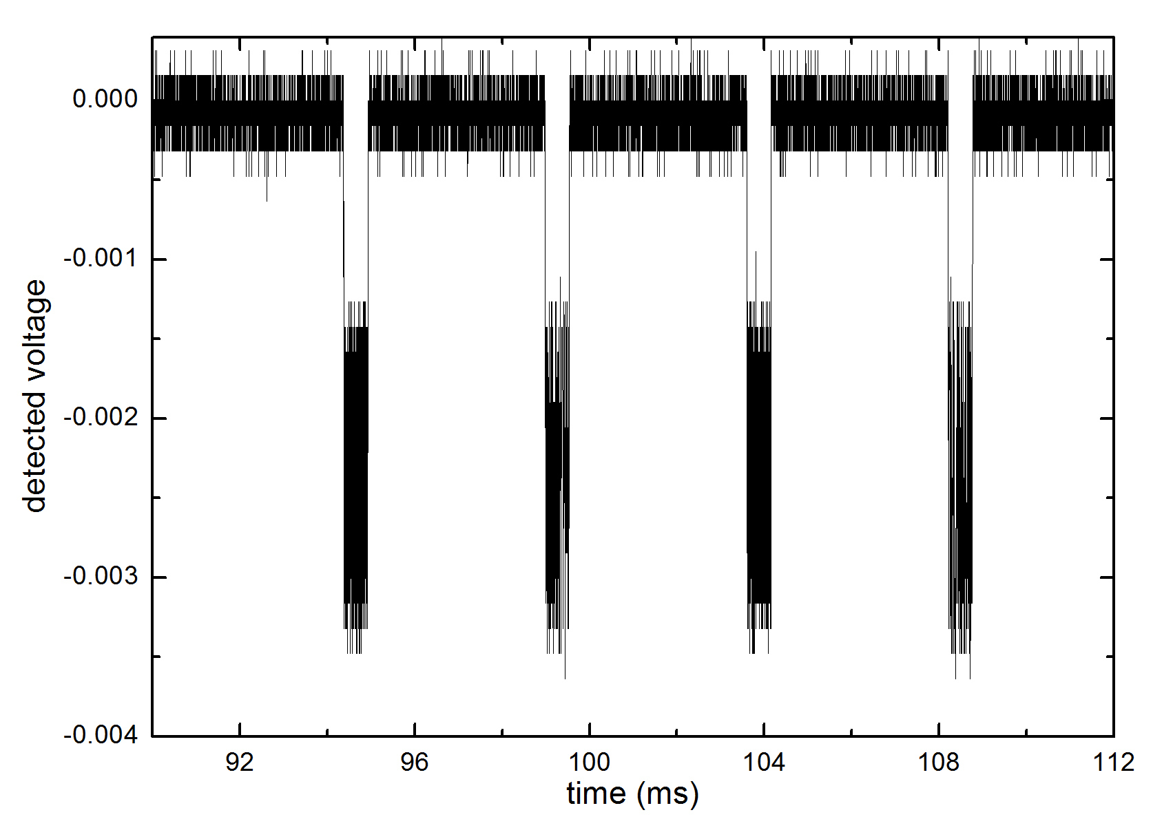
The amplitude noticeably subsided, but the signal is still being detected. This may be the result of inaccurate linear polarization, or just the accuracy of the orientation of the axis of the phone.
Since we looked at the detected signal, why don't we look at the signal itself live? The frequency, of course, is a bit high, but now there are also fast oscilloscopes. Here is the result:
Symbols - actually measured data, curves - splines on two data sets during one attempt to dial, horizontal normalization over a period of oscillations, animation step - a thousand periods. The floating phase, as I understand it, is precisely the result of the modulation used in mobile communications.
You can try to use the final design in one of two ways. Option number one - wipe off all prints and other traces of vinegar and collect the extract inside the shining copper. Option number two - connect the product with a coaxial cable with a connector for an external antenna in the phone. When traveling to remote places, she can help well with the quality of communication, if, of course, she can guess with the direction to the tower and polarization.
Thank you for your attention, I hope it was interesting.
The result is presented on KDPV. The white balance was deliberately chosen wrong, because with the right balance, as we shall see, the surface of the foil is of a somewhat unpresentable color. But to embellish is not our method, so all the other pictures are “honest” - bitter is better, but true, than pleasant, but flattery (s).
First we need to measure the frequency range in which the phone communicates with the nearest towers, because The device itself was three-band: 900/1800/1900 MHz. Since we do not need coordination or total power to determine the range, we can use the simplest loop antenna with a diameter of about 300 mm inserted into the central contact of the input port of the spectrum analyzer. It is said - done, the range of 900 MHz. Not very nice, because the size of our future ward is the maximum possible. The wavelength is about 330 mm, half of it is 165 mm, which means, as textbooks teach us, it is reasonable to use a waveguide section of about 200x100 mm (the middle octave between the cut-off of the main mode and entering the waveguide of the second mode). It is reasonable, it is reasonable, but where to get this multi-kilogram monster? And what if we make it from foil fiberglass? The dimensions are small, the material is enough, stiffness, most likely, too. But what about the antenna itself? If you do it properly, you will have to open about a meter, and the length is even longer. Taking into account the doubts about the rigidity of such a structure and doubts about the sufficiency of materials, as a result, a volitional decision was made - to open up to 400 mm, and to limit the length of the structure to 600 mm. At the very least, it is worthwhile to pass primary tests, before making a structure comparable to a relic radiation detector.
')
The ruler and the marker are in the hands, later - the metal shears, as a result we have four nice blanks, from which we solder the horn antenna itself and the coaxial-waveguide junction in the form of a single product. At first glance, the surface of the foil was clean, so I decided to do without the skin and immediately began the process of soldering with the help of the usual POS-60 and rosin. We combine two blanks, fix an approximately right angle between them (I did without a square), grab it from one end, then at the bend, and finally at the second end. The textolite is thin, which means it is light, so this is already enough to prevent the structure from falling off under its own weight. Next, we completely solder the seam from the inside. But it was not there - on the first seam it took about half an hour, besides, the last two seams would have to be done under conditions of increasing claustrophobia from the assembled structure. Rejecting the reluctance to dirty clean pants flying with dust from the skin, I still cleaned the surface for soldering, after which I tinted all the common edges of the blanks. After this, the process of complete propaying of one seam with the control of the light propagation began to take a couple of minutes, and the implementation of the last two seams is not so much more complicated than the first. Outside closeup:
The seam looks in my opinion quite well, the waviness in a fraction of a millimeter, which is quite acceptable. Now we are making a short-circuiting piston from PCB scraps. To do this, bend the U-shaped billet, the central part of which is slightly less than the internal cross section of the waveguide part and solder the next piece to it, for which the piston can be pulled out if it is quiescent:
Solder the antenna with a length of less than half the short side of the waveguide to the SMA connector:
This is an unused curve option. Install it into the hole made in the middle of the long wall:
And we see the antenna from the front of the horn (you can see both the antenna and its reflection):
In principle, we are ready to measure with an oscilloscope, but for insurance, first of all, let's see what level of power we can encounter. The World Encyclopedia gives us the following data: the maximum radiated power of mobile phones of the standard GSM-1800 is 1 W, for the GSM-900 it is 2 W. These capacities are large enough, the coaxial detector will not work in quadratic mode. To reduce the power and transfer the detector closer to the correct mode, we set the attenuator to 15 dB (more, unfortunately, it was not found, it would be better for thirty-fives). Go to the tests on the oscilloscope.
We put the phone on a wooden chair, turn on dialing and put a horn with a connected detector on top of the phone. First, we make sure that the maximum amplitude of the received signal is reached exactly in the center of the horn while the phone is long (vertical) in parallel with the horn antenna, then adjust the position of the piston to the maximum signal. Now you can begin to remove the "meaningful" waveforms from the detector. None of the tests was able to achieve a signal amplitude of more than 200 mV. Unfortunately, this value is higher than the range of calibration available in our hands:
Nevertheless, it is possible to extrapolate the data to the right and obtain a power value of about +3 dBm (the decimal logarithm of the power divided by 1 mW). Add here 15 dB attenuator and 3 dB to the symmetrical radiation inside the antenna and in the opposite direction (check the phone's flipping). Total we get +21 dBm or 126 mW. The value, in my opinion, is quite reasonable. Unfortunately, attempts to force the phone to lose the signal of the base station and to increase the transmission power to the maximum were unsuccessful. For this, a screened room or a Faraday cage with a grid much shorter than the wavelength would be perfect, but nothing similar was found nearby. For some reason, I did not want to take out the roll of the chain-link netting and wrap it with it. Thus, no definitive answers were received, and I even thought not to publish the article. But, after some thought, I decided that a small addition of graphs would brighten up a DIY article.
In the picture below, there are two data sets - during an attempt to dial and during a conversation:
Strangely enough, but during the conversation (red curve) data is transferred even less. The same schedule details:
The frame duration approximately corresponds to the nominal value of 577 μs, the period also corresponds to the nominal value - eight frames. Some readers probably have a question - how can you transmit voice data at a frame rate (bits) of about 200 Hz (and in fact and below)? The fact is that for data transmission, not amplitude, but quadrature modulation is used. Without going into the wilds of this not the simplest object, I will say that one frame is not one bit, obtained using amplitude modulation, but a whole data packet, modulated not amplitude, but phase-wise (in fact, it is still trickier, but , beyond the scope of the article). Naturally, after simple detection, we see no traces of the phase. I note that the average power is less than the peak power eight times due to the intervals between the frames, and once again at five due to the sparsity of the transmission intervals.
To prove the linearity of the polarization of radiation, we remove the signal by turning the phone 90 degrees around the direction of the horn:
The amplitude noticeably subsided, but the signal is still being detected. This may be the result of inaccurate linear polarization, or just the accuracy of the orientation of the axis of the phone.
Since we looked at the detected signal, why don't we look at the signal itself live? The frequency, of course, is a bit high, but now there are also fast oscilloscopes. Here is the result:
Symbols - actually measured data, curves - splines on two data sets during one attempt to dial, horizontal normalization over a period of oscillations, animation step - a thousand periods. The floating phase, as I understand it, is precisely the result of the modulation used in mobile communications.
You can try to use the final design in one of two ways. Option number one - wipe off all prints and other traces of vinegar and collect the extract inside the shining copper. Option number two - connect the product with a coaxial cable with a connector for an external antenna in the phone. When traveling to remote places, she can help well with the quality of communication, if, of course, she can guess with the direction to the tower and polarization.
Thank you for your attention, I hope it was interesting.
Source: https://habr.com/ru/post/398675/
All Articles