Guide to creating mechanical tentacles at home, part 3
Part 1
Part 2
In the last part, I will describe all the tools and techniques for the final assembly of tentacles. As promised, there are bonuses in the post.
" Files schemes .
1. Almighty list of materials
2. Vector drawings for the laser cutter.
a. DXF files with a shift of 0.003 "
b. Original DFX files
3. STL Models for a 3D Printer
4. Original CAD models of tentacles
5. Original CAD controller models
Depending on your purpose, some files will be more important than others. If you just want to make parts, you can immediately cut, using shear DXF files, parts from a sheet of the desired thickness, and proceed. If you need to tweak something in detail, I attached the original DXF.
')
And when we already have a bunch of new parts, let's go through the last steps necessary for the work of our child: assembly and adjustment.
Controller assembly
Each controller is two pulleys rotated at an angle to each other and fixed one above the other. Although we collect everything ourselves, do not despair - I will explain difficult places.
1. Assembly of 4 pulleys.
To comply with the sequence of operations, refer to the animation. Installing all components requires choosing the right tools.
Components:
• 4-40 Heat-setting sleeves with internal thread - 2 pcs
• M2 Heat-setting sleeves with internal thread - 16 pcs
• Rivets d 0.125 ", 9/16" long - 44 pcs
• outer_pulley_plate - 8 pcs
• inner_pulley_plate - 8 pcs
• Corners 612K-ND - 16 pcs
• Hexagon screws 4-40, 3/16 "- 16 pcs
• Small washers - 16 pcs
Instruments:
• Riveting Press
• Soldering iron
Rivets
In my garage I use a miniature press for rivets, but such a tool can also be found in the hackerspace.
Heat-setting sleeves with internal thread
To install such bushings is a task that at first glance seems to be difficult. But in fact, you only need to heat them with a soldering iron at a temperature of 250 C and carefully insert them into the part. You do not need to press on the soldering iron - just give the tip a slight vibration, and it will lower the bushings with its own weight. Each takes 15-20 seconds - take your time.
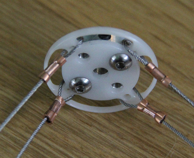
Cable clamps

To comply with the sequence of operations, refer to the animation. Do not forget that the cable passes between the washers and the upper corner.
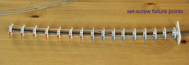
2. Installing sleeves in pulley plates
In the diagram below, I have designated all the places to insert heat-fixing sleeves (STI) into the plates. The diameters of the holes are specially selected for these bushings.
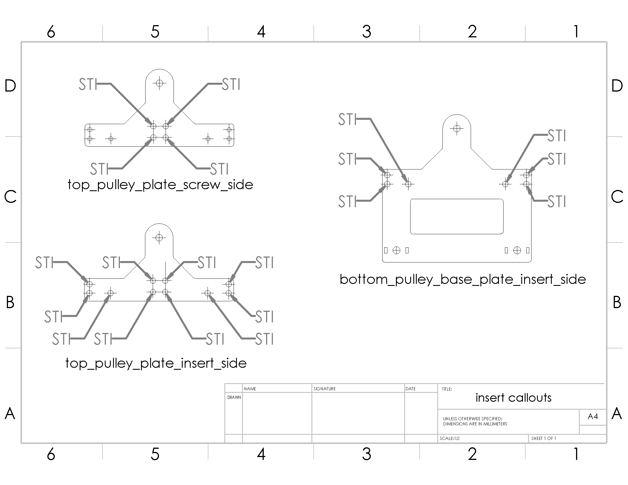
Components:
• 4-40 Heat-setting sleeves with internal thread - 40 pcs
• top_pulley_plate_insert_side - 2 pcs
• top_pulley_plate_screw_side - 2 pcs
• bottom_pulley_base_plate_insert_side - 2 pcs
3. Countersinking brackets
The brackets will fasten the upper and lower pulleys of the controllers. Countersinking is necessary in the following places.
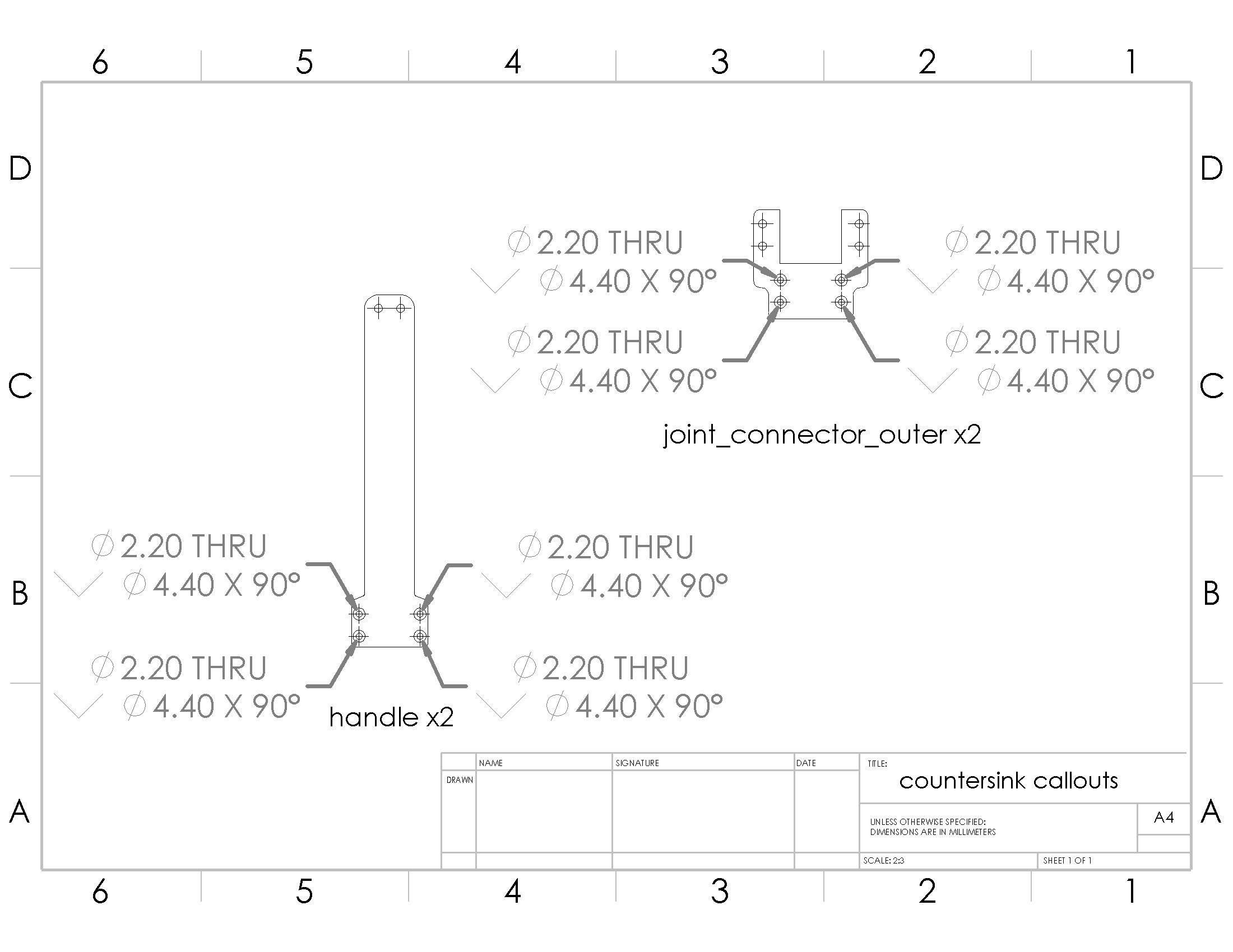
Components:
• handle_plates - 4 pcs
• joint_connector_outer plates - 4 pcs
Instruments:
• countersink + stop and hand drill (or machine) OR
• countersink + machine with stop
Details: depth tolerances
The screws that pass through the holes in the plates should reach the sleeves located at a depth of one or two plates. Using countersinking, it is necessary to create hidden nests in which the screw heads will hide at least flush. It is possible and deeper, only so that the screws do not protrude from the other side beyond the sleeves.
4. We connect parts of controllers
Components:
• assembled pulleys - 4 pcs
• top_pulley_plate_insert_side - 2 pcs
• top_pulley_plate_screw_side - 2 pcs
• bottom_pulley_base_plate_insert_side - 2 pcs
• bottom_pulley_base_plate_screw_side - 2 pcs
• spacers between pulleys - 4 pcs
• joint_spacer - 4 pcs
• joint_connector_outer - 4 pcs
• 6mm M2 flat head hexagon screws - 16 pcs
• 8mm M2 flat head hexagon screws - 16 pcs
• step screw - 4 pcs
• 8-32 nuts - 2 pieces
• Printed on the 3D printer part cable_insert_bracket with mounted rims - 4 pcs
• .5-in 4-40 hexagon socket with internal thread - 4 pcs
• .25-in 4-40 hexagon bolts - 12 pcs
• 3/16 4-40 spherical Allen screws - 32 pcs
• 612K-ND corners - 16 pcs
Instruments:
• hexagons
Details: sequence of actions
I would recommend to assemble the lower and upper halves separately, and then join them together. To connect the halves, we use the 612K-ND angles that I mentioned earlier.
Details: diameter for pulley axles
Stepped screws should easily pass through pulleys.
Details: we fix the controllers
After assembling the controllers it is convenient to fix on the rails OpenBuilds VSlot 20 × 20. Thus, it will be possible to choose a convenient distance between them for the person who is going to control them.
With all controllers - go to the tentacles.
Building tentacles
In this section, we will go through the assembly of a tentacle and its connection to the controllers.
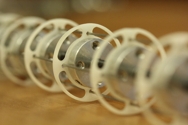
1. hub preparation
Components:
• hubs and screws - 18 pcs
• polyformaldehyde segments - 18 pcs
• 4-40 x 3-16 in. round head hexagon screws - 36 pcs
Instruments:
• drill
• 4 mm drill bit
Each segment-vertebra consists of a hub, a plastic plate and two screws (four can be screwed in, but they will be superfluous and only add weight). Twist 18 vertebrae.
Details: hub diameter
Depending on the diameter of the core used, you may need to increase the diameter of the center hole. It is convenient to clamp all the hubs in a vice and ream the hole to the desired diameter.
2. Cutting the cable of the desired length
Components:
• cable - 7.6 m
• limit switches - 4 pcs
Instruments:
• cutting pliers
• ticks for limit switches
• optional - mini-burner
1. Cut 8 pieces of cable of 914 mm each.
2. Optionally: heat one end of each cable on the burner to white heat for 8 seconds, and let it cool. As a result, it does not fluff.
3. Take 4 cables. Put the limit switches on the unfired ends.
3. Build a vertebra in the fold
Components:
• End switches - 4 pieces
• The remaining 4 unclamped cable - 4 pcs
Instruments:
• Crimping for cables
1. Take the 4 remaining cables.
2. Wrap each of the ends around one of the horizontal segments of the vertebra.
3. Clamp the cable.
4. Preparation of the upper segment cables

Components:
• Vertebrae - 8 pcs.
• Crimped cables - 4 pcs
• Speedometer cable or flexible channel, 610 mm
• Spring guide, 610 mm - 4 pcs
Instruments:
• 1.5 mm hexagon
1. Put one vertebra on the end of the flexible core. Hexagon attach it to the end.
2. Put on the seven remaining vertebrae and distribute them evenly. While slightly tighten them with a hexagon. The core should be filled with vertebrae approximately one third the length.
3. Pass each of the four cables through the corresponding openings of the vertebrae. Thread so that the limit switch rests on the upper vertebra.
5. Preparation of cables for the lower segment with a bend point
Components:
• 7 vertebrae
• Vertebrae from the fold with cables connected to it.
Slide the infidelity of the vertebrae into the bottom.
1. Thread the core through the bend vertebra and screw it lightly.
2. Put on the remaining seven vertebrae and lightly screw them. Pass the 4 cables through the corresponding holes. The whole structure should occupy approximately 2/3 of the core length.
6. Attaching the lower stopper

The key to quality management is a well-fixed stopper. I have a square piece of plastic connected to the base. No magic, just an extra hub and plate connected to the lower segment.
7. Align the vertebrae.
For each half of the tentacle, make sure that the vertebrae are standing evenly and evenly, then tighten them properly.
8. Threading cable channels
Components:
• Springs 610 mm long - 4 pieces
• Springs 457 mm long - 4 pieces
Instruments:
• Nippers
Almost done! Springs become channels for cables. Four of them end at the base of the tentacle. The other four are at half length, at the fold point, passing through the bottom section of the tentacle.

1. Slip the long channels over the four cables. Each of them passes through the lower part of the tentacle. Bring them to a point of a bend and put it in it.
2. Thread the four short channels to the base of the tentacle.
It's time to join the controllers!
9. Connection tentacles with controllers
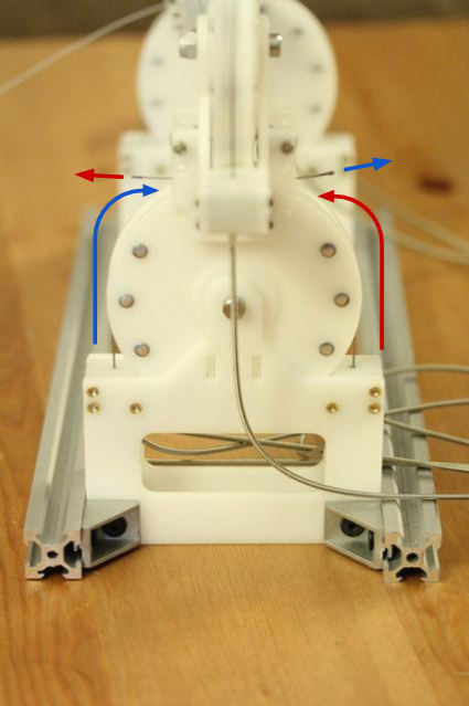
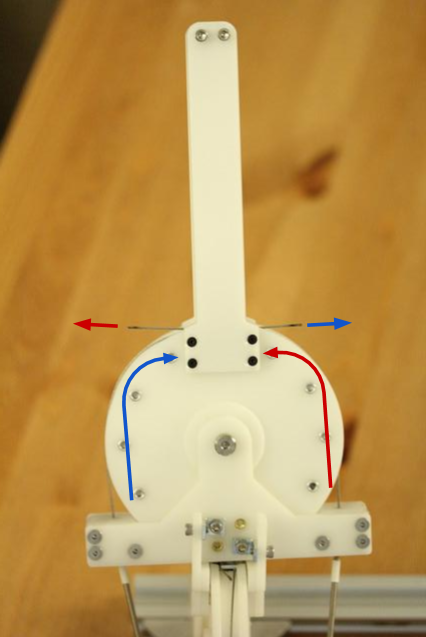
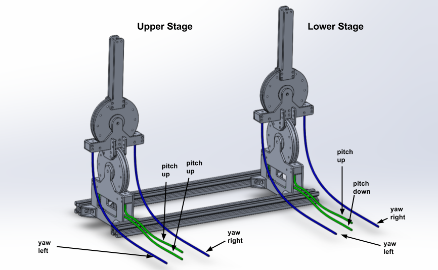
Each degree of freedom of the tentacle is controlled by two complementary cables, and each half has two degrees of freedom. Each controller pulley is connected to a pair of complementary cables to ensure mobility in the selected plane.
We need to understand the pile of cables we have and choose complementary pairs. You can temporarily seal them with scotch tape.
Pass each pair into the opposite clips printed on the 3D printer and clamp it with the corners on the pulleys. Choose the entire extra length of the cables - they should be stretched. You need to tension them until the cable channel rests on the printed holder. Screw the wire clips. Repeat for each pair.
10. Tensioning cables
With two hands, pull the supplementary cables, and with two other hands (a partner may be needed here), tighten the corner clips of the cables properly.
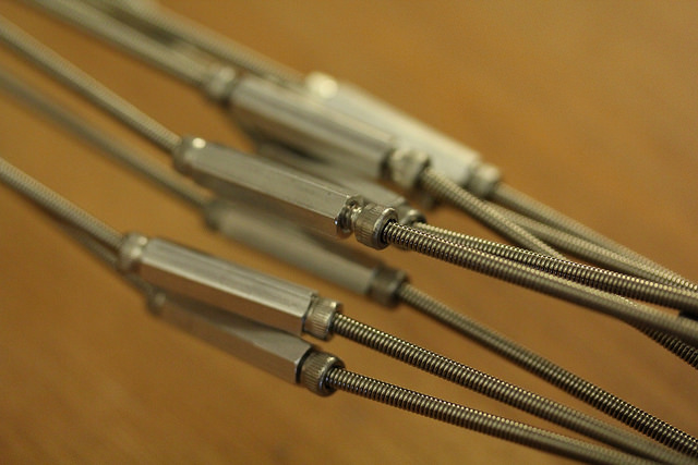
This method of stretching will fit perfectly, but I can offer another - to design a tensioning mechanism of hexagon bushings and bolts with an axial bore. Spin the bolt, the tension increases - the third hand is no longer needed.
11. Attaching the base
Tentacle movements are best obtained when its base is well secured and the entire “spine” resists twisting. I used a small vice, but this part of the plan can be improved.
Total
If you have reached this place and collected a new shiny tentacle - my congratulations! Now make 20 of these pieces, attach them to the top ten servomotors and make them move to the rhythm of the music. I hope that the interested reader has managed to learn interesting lessons from these articles, and thank you for staying with us.
Source: https://habr.com/ru/post/398605/
All Articles