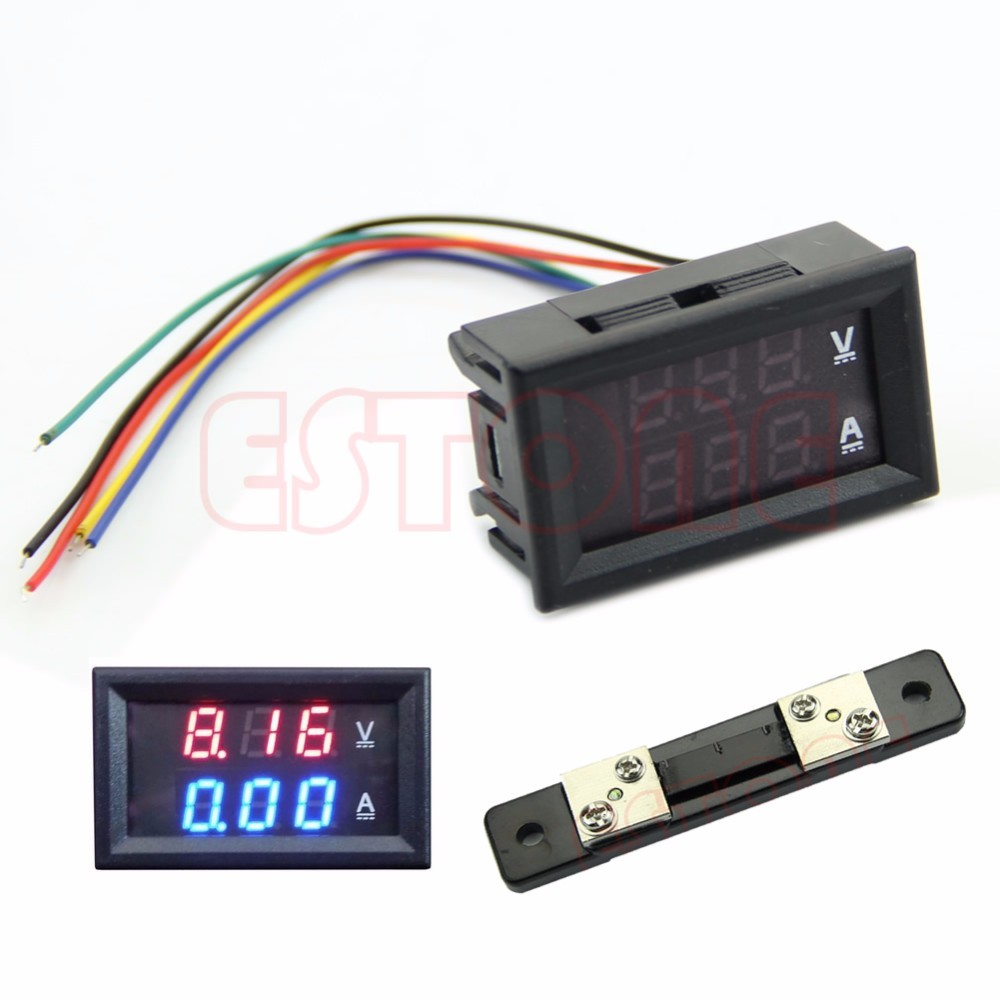
Refinement of a Chinese voltmeter WR-005
For my next project (reworking the ATX BP 580W in the laboratory), I bought the above-mentioned indicator . Not immediately and at the wrong time, it turned out that his power input is galvanically connected to the negative input of the shunt. This introduces a tangible error when powering the indicator from the same source from which the current is measured (error up to ampere with my shunt at 50A!). It was possible, of course, to pile up another duty room and power the indicator from it, but it seemed to me too fat and I decided to knock the indicator itself.
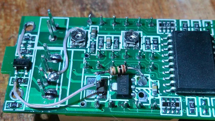
A search on the Internet found his twin brother YB27VA and its standard scheme. I must say that the layout of my device is slightly different. The essence of the rework is to decouple the differential input of the ad8605 op-amp (marked as B3A) from the common power wire. For rework, you will need initial skills of reverse engineering (to make sure that the circuit is the same), small parts soldering and Ohm’s knowledge :)
Scheme before rework:

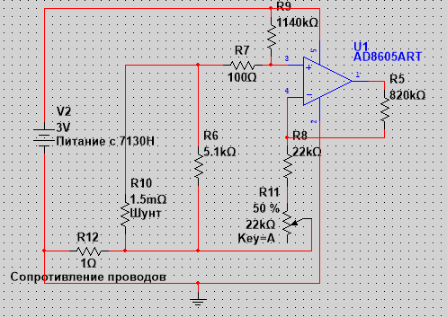
Scheme after:
')
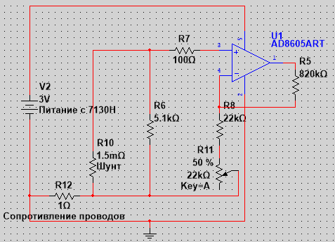
Red marked cut tracks. I decided to refuse the resistor R6, since it seems that it is needed only for the ammeter to show “0” with the shunt disconnected. Also, the transfer of the power of ad8605 (2 legs) is not necessary (judging by the tests in the simulator).
The second alteration solves the problem related to the fact that the indicator does not “see” the first ~ 180mA of current, that is, when applying to the 1A shunt, the device shows 0.8A, if you apply 0.2, then zero and so on. This is due to the offset input of the op amp and the ADC. It can be calculated, knowing the resistance of the shunt and the amount by which the device “lies”. I got 270mkV at the input of the shelter. It is easy to create this displacement artificially by adding one resistor to the circuit; as a result, the instrument will start measuring from zero.
In my case, it was necessary to add a 1140kΩ resistor from the integral stabilizer to 3V to the “+” of the OU input. This resistor, together with the R7 and the shunt forms a divider that specifies the initial offset.
The composite resistor turned out exactly as needed, due to the error of one of them :)
As a result, it now measures, starting from 50mA, up to 50A with a minimum step of about 20mA (0 also shows). Linearity is also not pumped up, but, sometimes, skips a unit, for example, from 0.12 immediately to 0.14 jumps.
The accuracy achieved pleasantly surprised me, it turned out to be a real measuring device that can be used in a laboratory power supply unit as the main indicator. Which you can even believe :) (this applies, at least, to the current). It is not clear why the Chinese decided to save on a couple of penny parts. Their cost is clearly an order of magnitude lower than other components, for example, the ad8605. Use good devices :)
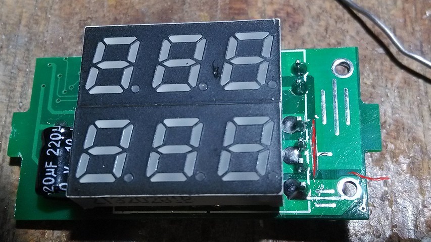
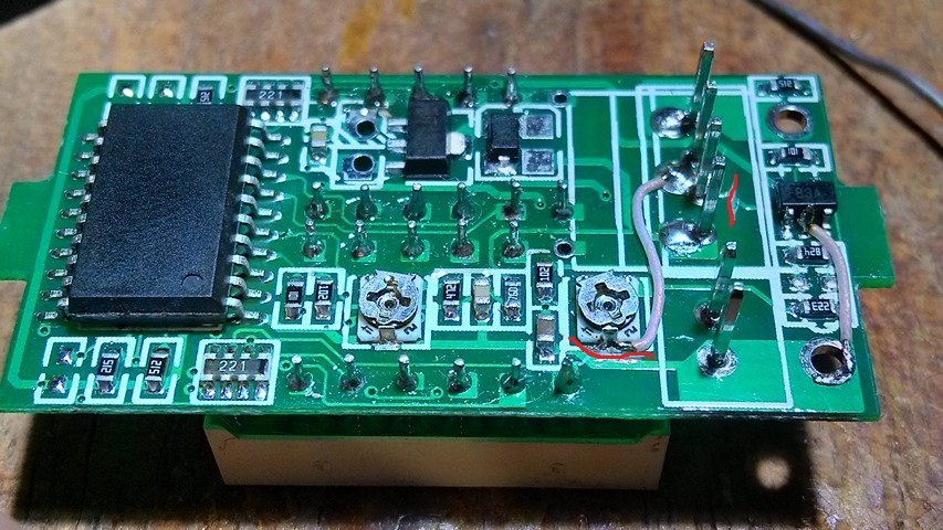
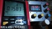
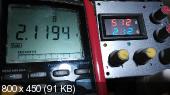
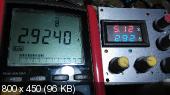
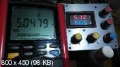
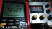
More photos with measurement results:


PS I already wanted to publish the article, but decided to check - and how are things going with tension? It turned out that the situation is also not good - the device is lying at 0.1V, and it is not elegant to fix it, because the lower resistor is trimming. But I still soldered a resistor there for 20MΩ and the result suited me)
» Link to device ali
» Reviews of his twin brother
A search on the Internet found his twin brother YB27VA and its standard scheme. I must say that the layout of my device is slightly different. The essence of the rework is to decouple the differential input of the ad8605 op-amp (marked as B3A) from the common power wire. For rework, you will need initial skills of reverse engineering (to make sure that the circuit is the same), small parts soldering and Ohm’s knowledge :)
Scheme before rework:
Scheme after:
')
Red marked cut tracks. I decided to refuse the resistor R6, since it seems that it is needed only for the ammeter to show “0” with the shunt disconnected. Also, the transfer of the power of ad8605 (2 legs) is not necessary (judging by the tests in the simulator).
The second alteration solves the problem related to the fact that the indicator does not “see” the first ~ 180mA of current, that is, when applying to the 1A shunt, the device shows 0.8A, if you apply 0.2, then zero and so on. This is due to the offset input of the op amp and the ADC. It can be calculated, knowing the resistance of the shunt and the amount by which the device “lies”. I got 270mkV at the input of the shelter. It is easy to create this displacement artificially by adding one resistor to the circuit; as a result, the instrument will start measuring from zero.
In my case, it was necessary to add a 1140kΩ resistor from the integral stabilizer to 3V to the “+” of the OU input. This resistor, together with the R7 and the shunt forms a divider that specifies the initial offset.
The composite resistor turned out exactly as needed, due to the error of one of them :)
As a result, it now measures, starting from 50mA, up to 50A with a minimum step of about 20mA (0 also shows). Linearity is also not pumped up, but, sometimes, skips a unit, for example, from 0.12 immediately to 0.14 jumps.
The accuracy achieved pleasantly surprised me, it turned out to be a real measuring device that can be used in a laboratory power supply unit as the main indicator. Which you can even believe :) (this applies, at least, to the current). It is not clear why the Chinese decided to save on a couple of penny parts. Their cost is clearly an order of magnitude lower than other components, for example, the ad8605. Use good devices :)
More photos with measurement results:


PS I already wanted to publish the article, but decided to check - and how are things going with tension? It turned out that the situation is also not good - the device is lying at 0.1V, and it is not elegant to fix it, because the lower resistor is trimming. But I still soldered a resistor there for 20MΩ and the result suited me)
» Link to device ali
» Reviews of his twin brother
Source: https://habr.com/ru/post/398579/
All Articles