Guide to creating mechanical tentacles at home: part 2, cable management
In the last article, we met with a two-step mechanism for tentacles. Today we will take a closer look at one of the many methods of manual control of these animals. And what is the coolest, this method is available for playback at home!
Without a control system, our home tentacle can only dangle in different directions, like overcooked macaroni. It is useless without a control mechanism that would give all cables adequate tension. Since the movement of the tentacles is controlled only by four pairs of cables, it is easy to estimate in the mind a system of motors to control them. But for a start, I decided to stop at the manual control, as is customary in the film industry.
')
Introduction to manual control
Manual control? Of all the possibilities of electronics, are we for some reason choosing this electronics-free cave approach? Do not worry. Manual control provides unique features that with its alternatives are not so easy to obtain.
First, this control will be purely mechanical. This means, in terms of spare parts, it is simple. No power source or code errors. As soon as we correctly attach all the cables and deal with possible problems, the controllers will simply work.
Secondly, unlike the servo, these controllers operate silently. No cheap servo chirping. If your elbows and wrists do not crunch, the sound when moving the tentacles is minimal. For enthusiastic directors, quiet props may become more attractive than an electronic alternative - even if they can then remove the sound during processing.
Third, manual control gives us feedback. If the tentacle bumps into an obstacle, the electronic control without a depression sensor will not know about it. As the arms are squeezed by the controllers attached to the cables that transmit tension along the entire length of the tentacle, we directly perceive the forces perceived by the tentacle. We can feel them, and we feel an obstacle.
Finally, professionals still use hand controllers as one of the control options. And although we do not make our 6061 aluminum alloy controllers, as professionals, our plastic alternative is not too different from the proven schemes of the past.
Reverse action
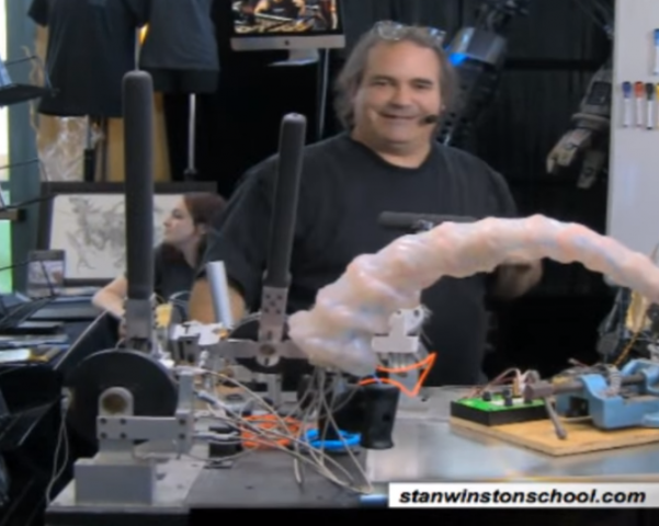
I mentioned that the feedback comes from attaching the cables to the tentacles. To demonstrate this visually, you can show such a funny thing as the opposite action. You can directly move the tentacle, and these actions will be transmitted through the cables to the controllers.
Inspiration for controllers
The controller is supposed to do with a laser cutter (although it also has one part of a 3D printer). Design is an adaptation of controllers that I have seen in the commercials of special effects masters.
Most of the controllers I've seen share degrees of freedom along two different axes, rather than integrating them into one. I think that this is because of the ease of manufacture, and also because of the freedom to follow the tentacle.
I made my controller based on the Stan Winston Tutorial training materials. And although they are similar in type, my controller is different in shape and sensations, since it is supposed to be made using a laser cutter.
The laser cutter option was chosen because not many have access to CNC machines. Laser cutters are found in schools and workshops (hackerspaces).
The largest change in the original design is the change of controllers in places. The movement of the lever controlling the "pitch" of the tentacle to the very bottom requires the use of the entire hand at once. And the same movement of the Landon controller is mainly based on the movements of the wrists. The change of controllers allowed me to unload my wrists, and I hope that others will like it too.
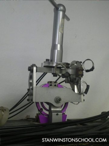
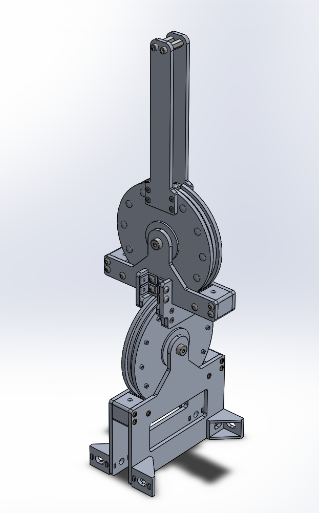
Controller design
Like the tentacle, the controller consists of many different parts that we have not yet mentioned. Here are its main parts and components.
Corners 612 and 621

Few ready-made parts I like more than these parts: 612K-ND and 621K-ND . I did not find another finished corner of the same small size. Moreover, they have a thread of 4-40, making it ideal for screwing in places where there is little free space.
But there is nothing perfect - and the corners of these parts are not always strictly perpendicular. But in this case it does not matter - with them I connect two perpendicular pulleys on the controller. They are held with two plastic plates, and the corners only fasten them.
Riveted pulleys
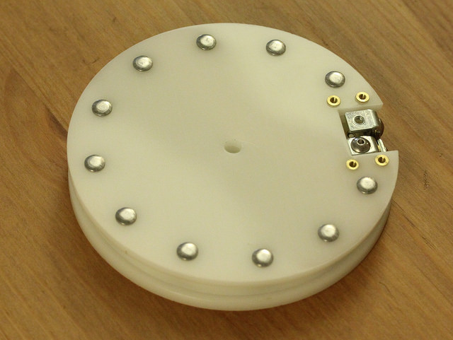
Pulleys consist of four plates. Being riveted together (acetal glues very poorly ), they work as one.
To the untrained eye, this detail may seem finished. But two important properties make the manufacture of this part more profitable than the adaptation of any finished. First, each pulley tightens and loosens the cables responsible for the movement. So, these cables must be firmly attached to the pulley. For this, I adjusted the two clips on top of the pulley. Secondly, the pulley must be connected either with the handle, if it is used above, or with another pulley, if it is below.
In both cases, the connection points are not in the center, and most ready-made pulleys do not have such mounting holes. In a CAD project, I included these holes in the plates. As a result, after laser cutting, a part with ready-made mounting holes is obtained. And since the pattern for them is the same for both the crank and for the joint connection of the pulleys, the upper and lower pulleys are identical.
Rivets
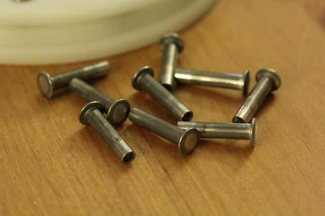
The pulleys are born in the form of four plates, but after assembly, they do not need to be disassembled. Therefore, I chose the rivets. They give the details a finished look, not to mention the pleasant moments with flattening the rivets during assembly. And it is easier to insert the rivet than cutting the thread everywhere and screwing in the screws.
Clips for ropes
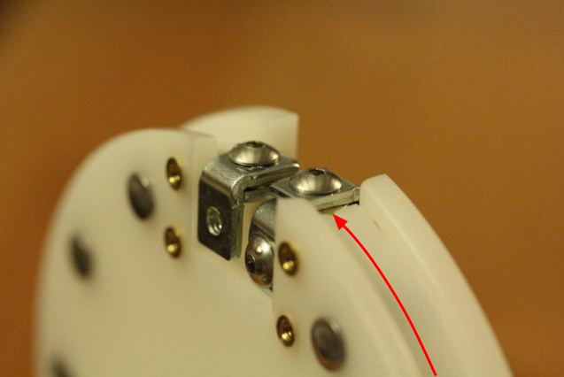
In the world of rapidly home-made prototypes, we are usually limited to soft or brittle materials, since most parts come from a 3D printer or laser cutter. In addition, the acetal has another problem - it is very slippery, so the clamp can not just press the cable to the plate. In such cases, it is necessary to transfer critical functions to the finished parts. Our clips are made of two steel corners. The cable is clamped between them and twisted so that the steel presses on the steel.
End of cable channel with clutch and 3D printer
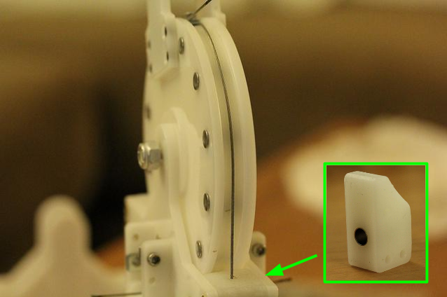
Each channel must end at a certain point in the controller so that the cable can go on and clamped in the pulley. When the pulley pulls on the wire, the channel does not move. The movements of the controller vary the length of the cable from the clamp to the end of the channel.
For this, I made a block on the 3D printer with a clutch inserted into it. These metal clutches can be found in bicycle and motorcycle stores, and they will protect the printed part from wear. Like the cable clips made from metal corners, these clutches will take the load off the parts we have manufactured.
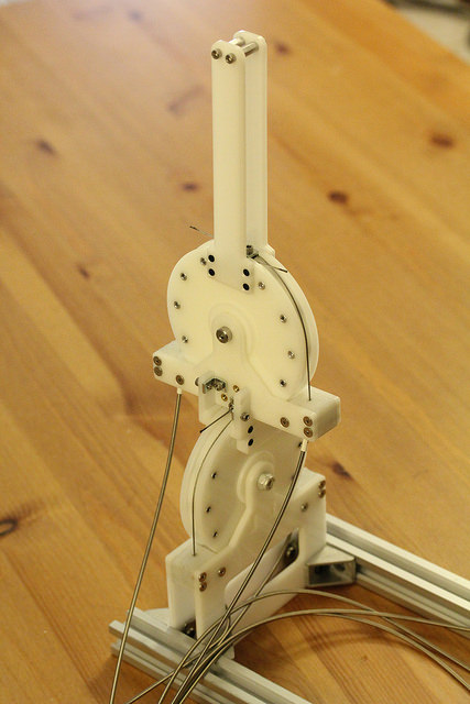
Attachment points
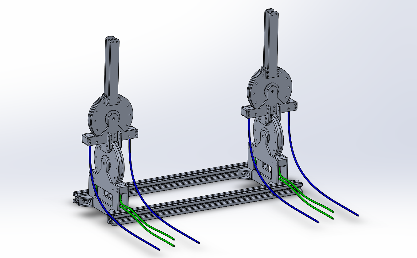
It’s impossible to predict the width of the shoulders of all people, so I added mounting brackets for the Makerslide staples. Thus, everyone will be able to cut off the guides of the desired length and fasten the controllers so that they can be conveniently controlled.
To be continued
I keep the photo log and CAD model up to date, and next time we will focus on assembling controllers and tentacles.
Source: https://habr.com/ru/post/398311/
All Articles