How I prosthetics UPS indicator
In the late 90s I had a UPS. Beautiful, with an LED indicator and a bunch of buttons, had two batteries inside and could support the life of my computer then (with the monitor!) For as much as 15 minutes. The times in Kamchatka were then hard, the lights were turned off regularly, so this device was very helpful. I went through with him the entire energy crisis, and more than once he saved my coursework from the sudden loss of electricity. And yet, it was possible to connect a tape recorder to it and, by candlelight, listen to the radio or your favorite tapes, preparing dinner for yourself on a portable gas stove ...
Naturally, UPS broke down. The first time his transformer burned down. Not the one that is big and stands in the inverter, but some small one, probably, for measuring the voltage in the network. Not finding the same factory one, I set up a self-made one, and the device worked for some time. Then stopped. For a long, long time, I could not find the reason. We had to unsolder different parts, check them for operability and solder them back. The problem was not. The gutted device lained under the bed for a couple of years, until one fine day I had the idea to apply 5 volts directly to the controller. And lo and behold: there was a squeak of the built-in speaker and numbers appeared on the LED indicator. He was alive! Next - a matter of technology: I walked along the power supply circuit with a voltmeter and found out that a fuse was soldered on the board, which looked like a resistor in a brazen manner! The fuse (burnt out naturally) was replaced and the UPS came to life.
Unfortunately, my repair and two years under the bed did not pass for the device for nothing. Somehow, in an incomprehensible way, the port burned in the controller, which was responsible for the glow of the green On-Line LED and the lowest segment of all digital segment indicators. There is nothing you can do - I had to accept. After a while I left Kamchatka and our paths diverged.
')
Years passed and, arriving to visit my parents, in the far corner I found my favorite bespereboynik: abandoned, dirty, without batteries and rubber feet. By that time, I had already acquired my own housing in another city, so it was decided to take the device to my place, restore its working capacity and use it for its intended purpose.
Task
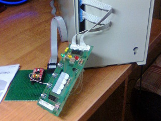
First of all, the UPS was washed and dried. Then, in a certain shop of radio components, suitable rubber feet and new batteries were bought. Much to his surprise, a suitable transformer was found in the same store, instead of my homemade products. A couple of days of work, and washed, updated bespereboynik joyfully squeaked and began to charge their new batteries. Everything was good, but the indicator was still not working.
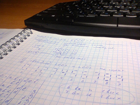
The idea to fix it came to me before. Having drawn all the numbers (and some letters) of the seven segment indicator on a notebook sheet, I realized that it is possible to determine the state of the lowest segment by the state of the others. The green LED can be turned on when other LEDs are off. There were a lot of thoughts about how this could be done: from a simple ROM chip to a simple FPGA. But, since I was a student and lived in Kamchatka, I did not have the opportunity to acquire something more complicated than small logic. Indicator repair was postponed.
This time I decided to tackle the problem seriously. Rummaging in the bins, I again did not find any ROM, or FPGA and any CPLD. On the other hand, the Arduino Pro Mini, or rather, its cheap Chinese clone with Ali Express, came under the arms. I bought Arduin in order to make a mini-computer based on a WiFi SD card from Transcend. Unfortunately, the card died during the experiments, and the board with the microcontroller was left idle. Nothing, we found her a new task!
Job
Dynamic indication is implemented in the display module: the segment signals are common to all four indicators so that only one of them is lit at a time. Moreover: as though the fifth indicator also connected three LEDs. Five selection signals allow you to specify which indicator (or LED strip) is being used now. These selection signals are successively scanned at a fairly high speed and, due to the inertia of vision, it seems that all indicators are lit at the same time.
At first, I wanted to get away with the simplest solution: an ordinary cycle that checks signals from six working segments, and turns the non-working seventh on or off. In fact, this is just an emulation of the ROM, about which I thought at the very beginning.
To do this, I had to connect six working segment to the input of the microcontroller, and a non-working segment - to the output.
Sketching a small array that matched the various states of the inputs with the output and the loop that bypasses this array, I loaded everything into the controller and immediately got a problem: the bottom segment was always lit. The first thought: a cant in the program. However, no matter how I looked at the code, no errors were found. In the end, it came to be understood that my cycle was not synchronized with the switching of indicators. If we read the state of the segments at the end of the cycle of selecting one indicator, then it is likely that we will light or extinguish the lower segment of the next one. Disorder.
Without thinking twice, I soldered five indicator selection signals to the remaining free inputs of the Arduino, configured them to generate an interrupt, and began to use an interrupt handler instead of a loop. It became better, but did not solve the problem. In the right places, the segment was burning as it should, but in those places where it should have been extinguished, there was not a bright residual glow.
After thinking for some time, I decided that this effect can occur if the search cycle in the array of the desired state for the segments takes longer than the indicator burning time. In this case, we also get out of our phase and manage the segment of the next indicator. It is necessary that between the time of receiving the interrupt from the select signal to the segment control command, as little time as possible should pass. It was possible to do this only in one way: make the code that makes a decision about the state of the segment from the interrupt handler, run it in the main loop with the lowest priority, and save the result in a certain global buffer. The interrupt handler will only have to read the value of their global buffer and quench or ignite a segment, depending on its contents. In the worst case, we can only be late with a change in the state of a segment in a certain indicator, but no longer climb on the next one.
That was the right decision. But finally everything worked only after I synchronized the decision-making cycle with an interruption using a spin-lock and disallowed the processing of the interruption during the operation of this cycle. And it not just earned, but earned as it should!
There was another problem with the indicators: most of the time they showed only numbers. However, after turning on the UPS, a testing process was launched, during which, in addition to numbers, two more words appeared: TEST and PASS. And if the letters T, E and P could simply be added to the array of valid characters, and S was similar to 5, then the letter A did not differ from the figure of eight, from the point of view of my program. The decision loop simply found the corresponding pattern in the array and finished drawing the lower segment. It was necessary to think of something to avoid it.
And I thought up. At the time of the arrival of a signal about a change of indicator, it is necessary to determine which indicator it belongs to and save the state of its segments into a variable specially assigned to it. Now, at any time, I can accurately determine the current content of all four indicators at once. And if on the first, third and fourth symbols P, 5 and 5 are displayed, respectively, then the second symbol is definitely A, and there is no need to light the lower segment. Just in case, I also added the processing of the word FAIL, which I have never seen, but the possibility of its appearance.
Everything, with the digital indicator is over. It remains only to fix the green LED "On-Line". But then a surprise was waiting for me ... The idea was this: the green LED (On-Line) always lights up alone. If the yellow (Battery) or red (Low Battery) LEDs are lit, the green should not be lit. Thus, we solder the wires from these LEDs to the microcontroller, set a simple if () with a logical “OR” and everything should work. But it turned out that when the yellow LED is on, it actually does not light up permanently, but flashes quickly. Quickly, but not enough, if () missed it and did not light the green LED. It turned out that when working from the network, the green LED lights up in a hollow brightness, but when switching to the battery, it burned at half the brightness, but still it burned. Well, not a problem, I thought, I will put a simple low-pass filter: I will cut off all the fast blinks, but leave only the slow ones that correspond to switching to the battery and back. The analysis of the flashing time of the yellow LED brought the following surprise: the period of impulses that are fed to it is very unstable and can reach quite large values. It turned out that the filter should pass signals no higher than 0.5-1 Hz. This is not very good, because we get a rather large delay in changing the On-Line signal, but it is quite tolerable.
I decided to make the filter very simple. We are 50 times, at equal intervals of time, monitor the status of yellow and red LEDs. If one of them is lit, then increase the special counter by one. Then, we check the value of the counter, and if the control LEDs are lit for 50% of the time being checked, then we consider that it is on, and if it is less, then it is off. In the process of debugging, we had to reduce this figure to 10%. Why - did not understand.
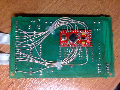
And it all worked! It only remained to beautifully mount the Arduino board in the UPS with a double-sided tape and a glue gun.
For the curious:
the resulting code
#include <stdint.h> #include <avr/io.h> #include <avr/interrupt.h> #define AVG_TIME 50 #define THS_TIME 45 #define SD_SEG_A _BV(0) #define SD_SEG_B _BV(1) #define SD_SEG_C _BV(2) #define SD_SEG_D _BV(3) #define SD_SEG_E _BV(4) #define SD_SEG_F _BV(5) #define SD_SEG_G _BV(6) #define SD_LED_RED SD_SEG_A #define SD_LED_YLW SD_SEG_C #define LD_SEL_LED _BV(0) #define LD_SEL_1 _BV(1) #define LD_SEL_2 _BV(2) #define LD_SEL_3 _BV(3) #define LD_SEL_4 _BV(4) #define GET_SEL (PINC & 0x1f) #define SD_SYM_NONE (0) #define SD_SYM_0 (SD_SEG_A | SD_SEG_B | SD_SEG_C | SD_SEG_D | SD_SEG_E | SD_SEG_F) #define SD_SYM_1 (SD_SEG_B | SD_SEG_C) #define SD_SYM_2 (SD_SEG_A | SD_SEG_B | SD_SEG_D | SD_SEG_E | SD_SEG_G) #define SD_SYM_3 (SD_SEG_A | SD_SEG_B | SD_SEG_C | SD_SEG_D | SD_SEG_G) #define SD_SYM_4 (SD_SEG_B | SD_SEG_C | SD_SEG_F | SD_SEG_G) #define SD_SYM_5 (SD_SEG_A | SD_SEG_C | SD_SEG_D | SD_SEG_F | SD_SEG_G) #define SD_SYM_6 (SD_SEG_A | SD_SEG_C | SD_SEG_D | SD_SEG_E | SD_SEG_F | SD_SEG_G) #define SD_SYM_7 (SD_SEG_A | SD_SEG_B | SD_SEG_C) #define SD_SYM_8 (SD_SEG_A | SD_SEG_B | SD_SEG_C | SD_SEG_D | SD_SEG_E | SD_SEG_F | SD_SEG_G) #define SD_SYM_9 (SD_SEG_A | SD_SEG_B | SD_SEG_C | SD_SEG_D | SD_SEG_F | SD_SEG_G) #define SD_SYM_E (SD_SEG_A | SD_SEG_D | SD_SEG_E | SD_SEG_F | SD_SEG_G) #define SD_SYM_P (SD_SEG_A | SD_SEG_B | SD_SEG_E | SD_SEG_F | SD_SEG_G) #define SD_SYM_T (SD_SEG_D | SD_SEG_E | SD_SEG_F | SD_SEG_G) #define GET_SYM (~PIND & 0x7f) #define BROKEN_SEG (SD_SEG_D) static uint8_t sd_symbols[] = { // list of known symbols SD_SYM_NONE, SD_SYM_0, SD_SYM_1, SD_SYM_2, SD_SYM_3, SD_SYM_4, SD_SYM_5, SD_SYM_6, SD_SYM_7, SD_SYM_8, SD_SYM_9, SD_SYM_E, SD_SYM_P, SD_SYM_T }; volatile static uint8_t sel, symbol; // current input signals volatile static short fb0, fb1, fb2, fb3, fb4; // display frame buffer // display routine ISR(PCINT1_vect) { sel = GET_SEL; symbol = GET_SYM; if (((sel & LD_SEL_LED) && fb0) || ((sel & LD_SEL_1) && fb1) || ((sel & LD_SEL_2) && fb2) || ((sel & LD_SEL_3) && fb3) || ((sel & LD_SEL_4) && fb4)){ PORTD &= ~BROKEN_SEG; } else { PORTD |= BROKEN_SEG; } } // // entry point // int main(void) { int cur_time; int led_on_time; uint8_t last_symbol_1, last_symbol_2, last_symbol_3, last_symbol_4; int i; // setup GPIO ports DDRC = 0; DDRD = BROKEN_SEG; // setup pin change interrupt PCICR |= _BV(PCIE1); PCMSK1 |= _BV(PCINT8) | _BV(PCINT9) | _BV(PCINT10) | _BV(PCINT11) | _BV(PCINT12); cur_time = 0; led_on_time = 0; last_symbol_1 = last_symbol_2 = last_symbol_3 = last_symbol_4 = 0; fb0 = fb1 = fb2 = fb3 = fb4 = 0; while(1) { // sync with display strobe sei(); while (sel == 0) {} cli(); // if select one of segment indicator if (sel & (LD_SEL_1 | LD_SEL_2 | LD_SEL_3 | LD_SEL_4)) { // looking for displayed symbol for (i = 0; i < 14; i++) { uint8_t sd_symbol = sd_symbols[i]; if ((symbol & ~BROKEN_SEG) == (sd_symbol & ~BROKEN_SEG)) { short val; if (sd_symbol & BROKEN_SEG) { val = 1; } else { val = 0; } if (sel & LD_SEL_1) { last_symbol_1 = sd_symbol; fb1 = val; } else if (sel & LD_SEL_2) { last_symbol_2 = sd_symbol; fb2 = val; } else if (sel & LD_SEL_3) { last_symbol_3 = sd_symbol; fb3 = val; } else if (sel & LD_SEL_4) { last_symbol_4 = sd_symbol; fb4 = val; } // PASS workaround if ((last_symbol_1 == SD_SYM_P) &&(last_symbol_2 == SD_SYM_8) && (last_symbol_3 == SD_SYM_5) && (last_symbol_4 == SD_SYM_5)) { fb2 = 0; } // FAIL workaround else if ((last_symbol_1 == SD_SYM_E) &&(last_symbol_2 == SD_SYM_8) && (last_symbol_3 == SD_SYM_1) && (last_symbol_4 == SD_SYM_1)) { fb1 = 0; fb2 = 0; fb4 = 1; } break; } } } // if select LED line else if (sel & LD_SEL_LED) { if (cur_time++ > AVG_TIME) { if (led_on_time < THS_TIME) { fb0 = 0; } else { fb0 = 1; } cur_time = 0; led_on_time = 0; } else { if ((symbol & (SD_LED_RED | SD_LED_YLW)) == 0) { led_on_time++; } } } // reset sync flag sel = 0; } return 0; } Source: https://habr.com/ru/post/397697/
All Articles