Another smart home, in several parts. Decorative lighting
Usually, the smart home begins (and very often ends too) with the control light bulb. Then there are bluetooth sockets, temperature sensors with WiFi, but light bulbs are the very first.
Well, I already know how to control ordinary light bulbs, I need to master LEDs.
')
Getting started.
With it, everything is very simple, three colors, 12 volts and software PWM. You can add a fourth channel for white tape, yet RGB LEDs do not give such white light as individual white LEDs.
Putting the controller.
4 channels with six-bit program PWM, front panel control - one variable resistor sets the chromaticity in the HSV space, the second one - brightness and saturation. The buttons can turn on effects, or discretely switch the color or brightness of the white channel. It is possible to connect to the network either by wire (RS485) or wirelessly (WiFi).

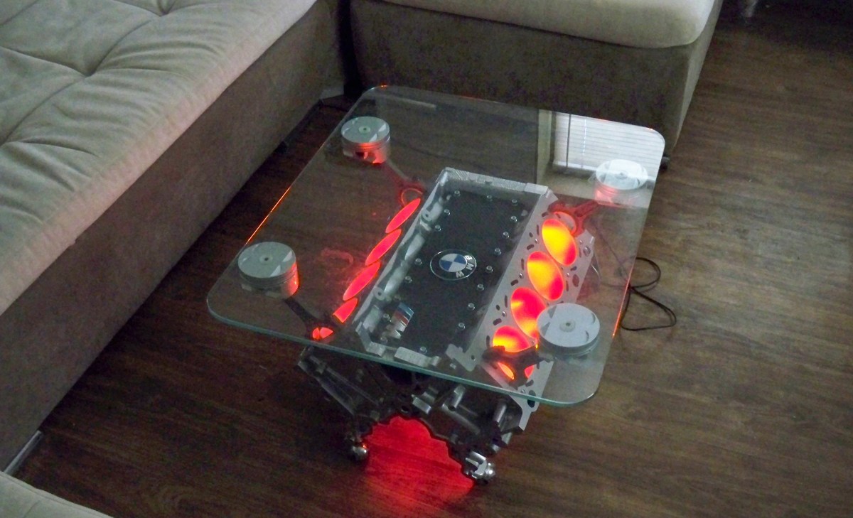
Install into place, add power supply, glue tape

And we get from the usual coffee table - an unusual

What can this controller? Set colors in RGBW or HSV space, 4 presets, 4 timers, sleep and wake timer, 8 effects with speed control.
But the tape is a tape, not everywhere it can be applied, therefore it was decided to make controlled lights.
The simplest option for addressable independent luminaires is a three-wire connection, two wires for power and one for control. But why pull one extra wire? There are two solutions for transmitting information over the power wires — add a modulated RF (more complex solution) or interrupt the voltage (simpler). I stopped at the second. The scheme of the transmitting part:

In the normal mode, the power is supplied to the line through Q2, when transmitting commands, the power lead is shorted to ground by the transistor Q1. The transmission speed is 2400 baud, the length of the parcel is 8 bytes, the pre-optimus, the address of the luminaire, the command with parameters and the checksum. Logically it is possible to connect up to 250 devices, but, taking into account the fact that, depending on the type of LEDs, the current consumption can be up to 500 mA per luminaire - then 250 is with a large margin. Perhaps group control of lamps, for which the address is allocated Broadcast.
Diagram of the receiving part (and the whole lamp)

At the entrance there is a diode bridge, so as not to think about polarity, then a stabilizer and a microcontroller. The USART input is connected through the R2-R3-R4 divider. In this embodiment, there is an unpleasant moment - the flickering of the LEDs during transmission, but this can be solved by installing a larger capacity and transferring the power point of the LEDs after D4.
The construct can be anything, I will show one of the options - a board in the form of a split ring

What can be done with a similar lamp? For example, from the usual garden lantern

make an unusual

Or, for example, from ordinary wood

do the unusual

And you can from the usual decorative fountain

make an unusual

A web-based control is available, where you can set color and brightness both in HSV space and individually for each channel, save and set presets, effects, sleep and wake-up timers, and so on.

Also there is a tab in the application for hours

There is a variant of luminaires without a central controller, with a WiFi module, but still it’s impossible to call them wireless. Yes, and there are doubts about the performance of WiFi under water.
Links to previous parts:
Well, I already know how to control ordinary light bulbs, I need to master LEDs.
')
Getting started.
LED Strip Light
With it, everything is very simple, three colors, 12 volts and software PWM. You can add a fourth channel for white tape, yet RGB LEDs do not give such white light as individual white LEDs.
Putting the controller.
4 channels with six-bit program PWM, front panel control - one variable resistor sets the chromaticity in the HSV space, the second one - brightness and saturation. The buttons can turn on effects, or discretely switch the color or brightness of the white channel. It is possible to connect to the network either by wire (RS485) or wirelessly (WiFi).
Install into place, add power supply, glue tape
And we get from the usual coffee table - an unusual
What can this controller? Set colors in RGBW or HSV space, 4 presets, 4 timers, sleep and wake timer, 8 effects with speed control.
But the tape is a tape, not everywhere it can be applied, therefore it was decided to make controlled lights.
LED controlled lights
The simplest option for addressable independent luminaires is a three-wire connection, two wires for power and one for control. But why pull one extra wire? There are two solutions for transmitting information over the power wires — add a modulated RF (more complex solution) or interrupt the voltage (simpler). I stopped at the second. The scheme of the transmitting part:
In the normal mode, the power is supplied to the line through Q2, when transmitting commands, the power lead is shorted to ground by the transistor Q1. The transmission speed is 2400 baud, the length of the parcel is 8 bytes, the pre-optimus, the address of the luminaire, the command with parameters and the checksum. Logically it is possible to connect up to 250 devices, but, taking into account the fact that, depending on the type of LEDs, the current consumption can be up to 500 mA per luminaire - then 250 is with a large margin. Perhaps group control of lamps, for which the address is allocated Broadcast.
Diagram of the receiving part (and the whole lamp)
At the entrance there is a diode bridge, so as not to think about polarity, then a stabilizer and a microcontroller. The USART input is connected through the R2-R3-R4 divider. In this embodiment, there is an unpleasant moment - the flickering of the LEDs during transmission, but this can be solved by installing a larger capacity and transferring the power point of the LEDs after D4.
The construct can be anything, I will show one of the options - a board in the form of a split ring
What can be done with a similar lamp? For example, from the usual garden lantern
make an unusual
Or, for example, from ordinary wood
do the unusual
And you can from the usual decorative fountain
make an unusual
A web-based control is available, where you can set color and brightness both in HSV space and individually for each channel, save and set presets, effects, sleep and wake-up timers, and so on.
Also there is a tab in the application for hours
There is a variant of luminaires without a central controller, with a WiFi module, but still it’s impossible to call them wireless. Yes, and there are doubts about the performance of WiFi under water.
Links to previous parts:
- Another smart home, in three parts. Part one, iron.
- Another smart home, in three parts. Part two, software and server.
- Another smart home, in three parts. Part Three, User Interface
- Another smart home. Part Four - connect the intercom
- Another smart home. Part Five - Big Red Button.
- Another smart home, in several parts. Weather station from scrap materials.
Source: https://habr.com/ru/post/397643/
All Articles