Overview of the Draytek 2925 Series Router. Part Two
In the first part of the review of the Draytek 2925n series of routers, we examined in detail how the device is positioned in the market, how the router is used, its key functions and examples of their use, got acquainted with the detailed technical specifications, looked at the configuration and appearance of the router, detailed the functions of indicators and interfaces devices.
The results unambiguously demonstrate the wide capabilities of the router, coupled with the “gigabit”, which may be needed by an SMB and SMB + enterprise level or a small branch of a large company that have “outgrown” 100Mbit / s network connections and need hundreds of megabits on the local network and WAN interfaces to the ISP. Therefore, the device has great potential for use in resource-intensive corporate networks. Load testing, the results of which you can see in the first part of the review, showed good results. The first part of the review is available at this link.
In this part of the review, we will take a closer look at the device’s web interface, learn about its features and an example of setting up such functions and interfaces as WAN and LAN, Load balancing, wireless network, VPN (PPTP, IPSec and SSL), firewall, NAT, special tools for auto configuration and centralized management of access points - Central AP Management and VPN connections on remote routers –Central VPN Management, bandwidth control, a function of creating a cluster of high availability from several routers, as well as USB functions, diagnostics and installation utoringa router.
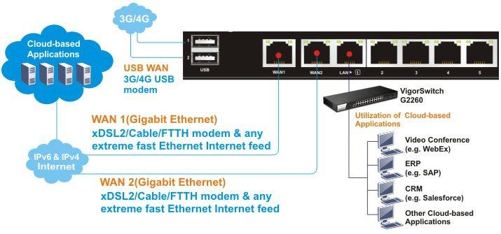
Below is a general wiring diagram of the router.
')
Fig. 0
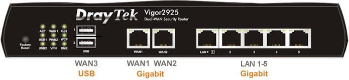
Fig. 0-1
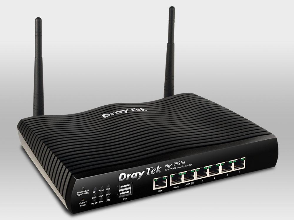
I pay attention that all Ethernet all ports of WAN and LAN are "gigabit".
By default, the router has an open wireless network called Draytek and a DHCP server, you can connect to it or use one of the LAN ports.
After connecting to the router from the PC and successfully obtaining the IP address from the 192.168.1.0/24 network, open its web interface, to do this, in the web browser, dial the default LAN IP 192.168.1.1, Username: admin, password: admin. I recommend immediately changing the password to a more secure one.
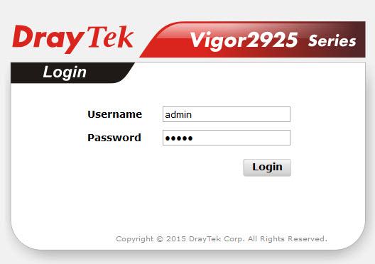
Fig. one
We get to the “ Online Status” menu , where the main information about the device is displayed.
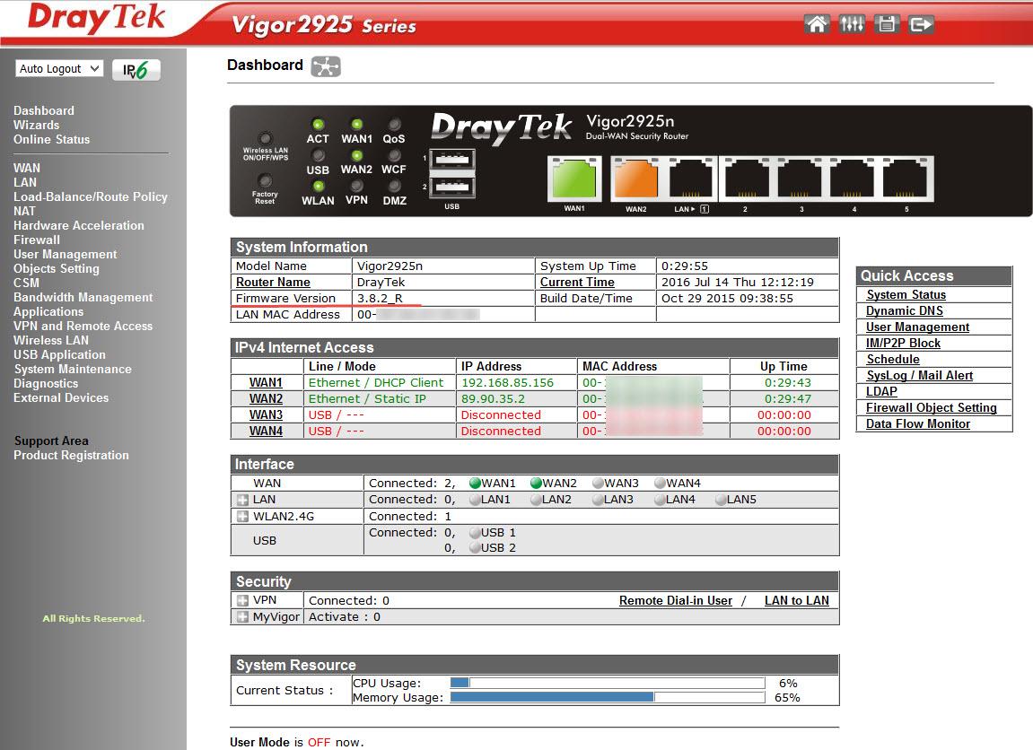
Fig. 2
Below, in the image, the “ Dashboard” menu is presented , in which the router’s connection to the WAN, LAN and wireless WLAN networks is clearly displayed. Simply and clearly
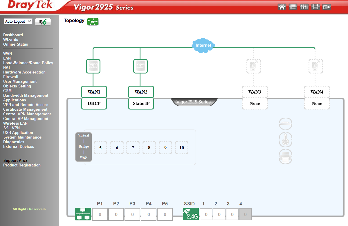
Fig. 2-1
I note that the firmware version 3.7.8.2_R is preinstalled on routers shipped to Russia, this firmware differs from the usual one in that it does not have encryption other than the PPTP protocol, it looks like this:
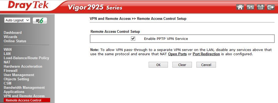
Fig. 3
If this is not enough, you can install a full-fledged firmware by downloading it from the Draytek.com website in the Supports section -> Downloads -> Firmware - Vigor2925 Series .
I chose the latest 3.8.2.3 and downloaded it, then, unzip it, in the web interface of the router, open System Maintenance >> Firmware Upgrade and specify the file v2925_3823.all, then click "Upgrade" .
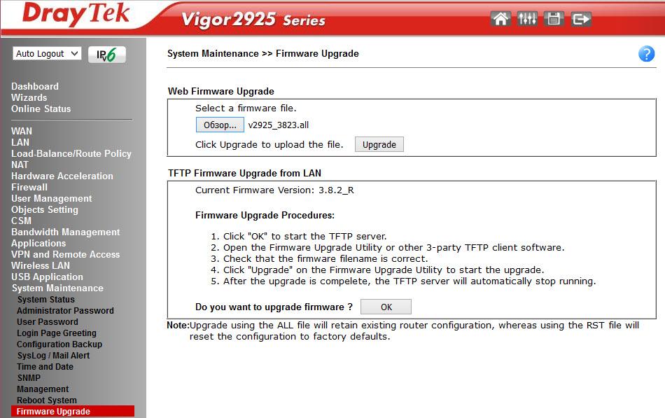
Fig. four
After a successful update, restart the router and get the latest firmware without any restrictions.
For clarity, below is an image of the network scheme for the Draytek 2925n router, for the example of which we will consider its web interface, as well as some examples of setting functions.
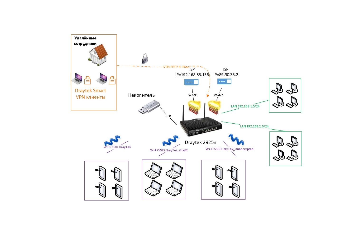
Fig. 4-1
To connect to the Internet, we use two WAN interfaces with several routing rules. In case of a failure on the first channel, the traffic will automatically go through the backup.
We use two subnets: LAN0 = 192.168.1.0 / 24 and LAN1 = 192.168.2.0 / 24. And three wireless networks with SSID: DrayTek, DrayTek_Guest and DrayTek_Unencrypted. They are integrated through VLAN settings with wireless networks. Remote clients can connect via VPN using Smart VPN Client and PPTP and IPSec protocols. For the SmartMonitor application, mirroring is enabled from the LAN ports.
In general, regardless of the model of the Draytek router, the menu structure has a similar organization, you can not find any functions, or discover more of them than in another model or firmware version, but the structure remains unchanged. On the left is a block of global menu items structured by router subsystems: Wizards, settings for wired network interfaces WAN and LAN, then a firewall settings block (Firewall, Objects Settings, CSM) and User Management, then a settings block special router applications (Applications). Then there are two menu items responsible for centralized management of Draytek - Central AP Management wireless points and centralized VPN management on Draytek - Central VPN Management routers. Then the VPN settings block, followed by the menu for setting up a wireless network (Wireless LAN), a separate menu for setting the USB port (USB Application), and finally the menu of service functions (System Maintenance) and the diagnostics menu of the router (Diagnostics).
All items are structured simply and logically, in accordance with the network functions, without any specific and confusing logic.
Each global menu item includes one or more sub-items. Consider the main menu items, since the router has a configuration corresponding to the network scheme that was presented above, as we review the new menu items, it will become clear how these or other network functions are configured.
Here are the settings wizards that allow you to configure the main functions of the router with a few clicks. They are a chain of several dialog boxes, the last window displays a listing of all the settings made and the “Finish” button to apply them. It seemed to me that the data of the wizard for very lazy administrators, as well as without them, setting up the basic functions on the router is easy.
Quick Start Wizard - used to quickly configure the connection WAN 1-3 interfaces.
Service Activation Wizard - activates an intelligent thematic filter Web Content Filter .
The following wizards of the VPN Client Wizard and the VPN Server Wizard seemed interesting to me, with the help of them it is easy to configure the VPN in the LAN-to-LAN and Remote Dial-in User modes, activate the service and register the users. Below, an example of 3 steps to add and activate a VPN user.
We chose PPTP, then you need to configure the client-side, we will use the Draytek Smart VPN client. Let's go back to the VPN settings in the VPN and Remote Access menu.
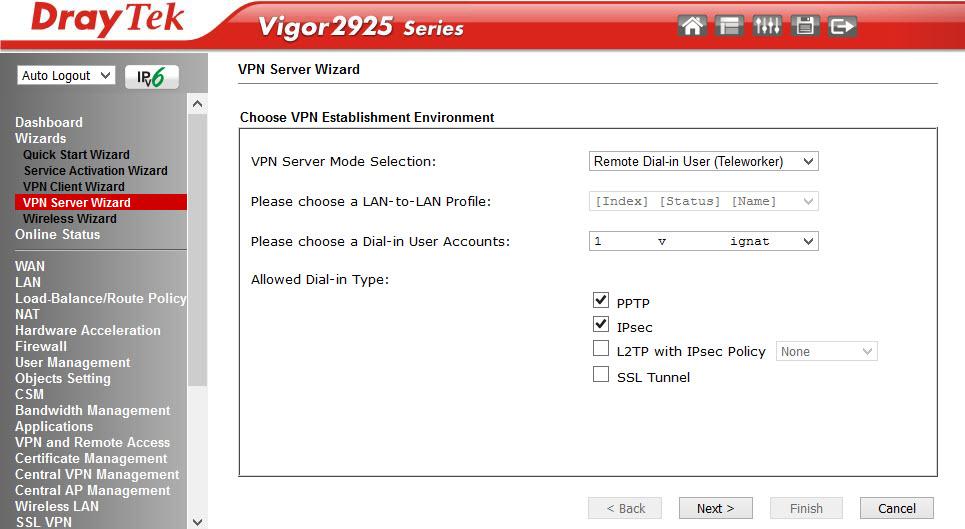
Fig. five
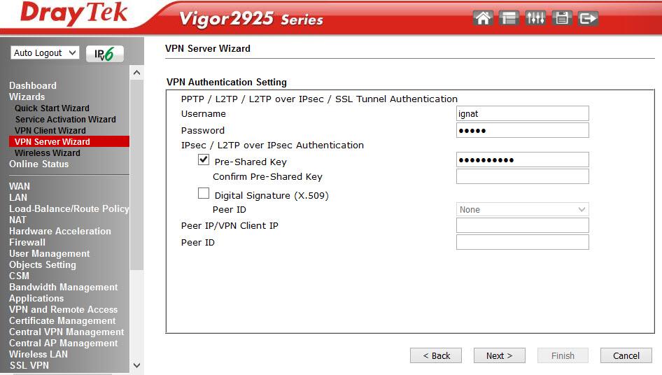
Fig. 6
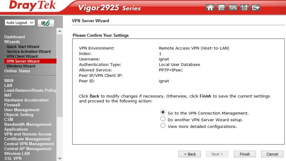
Fig. 7
Wireless Wizard Wizard is used for initial configuration of a wireless network. Below is the final window at the completion of the wizard.
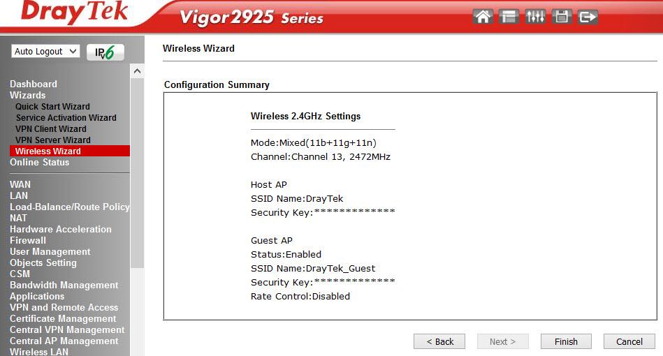
Fig. eight
In a couple of clicks, the wireless network is set up.
The next menu item contains two subitems: the first Physical Connection shows the physical status of the interfaces LAN, WAN 1-3 and link-level counters, the same thing, but only for virtual interfaces can be seen in the Virtual WAN menu.
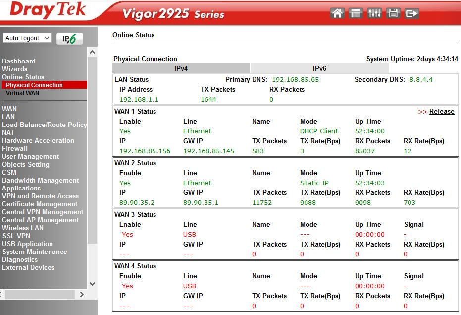
Fig. 9
More detailed information on the system status can be found in System Maintenance -> System Status .
In this menu, all settings related to the connection of the router to the Internet providers are made. In our example, WAN 1 and 2 are active:
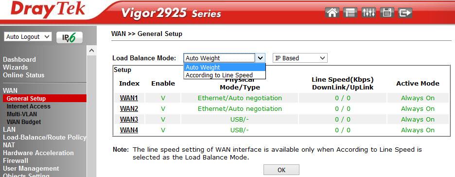
Fig. 10-1
Load balance mode setting is available when two or three WAN interfaces are used simultaneously. We use Auto Weigh mode; in this mode, the router automatically distributes the load. The WAN 3 interface can be used when connecting a 3 / 4G modem.
Below is the detailed configuration of the WAN 2 interface, we use load balancing mode.
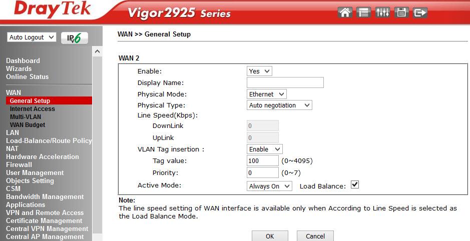
Fig. 10-2
In the Internet Access submenu, the interfaces are configured directly.
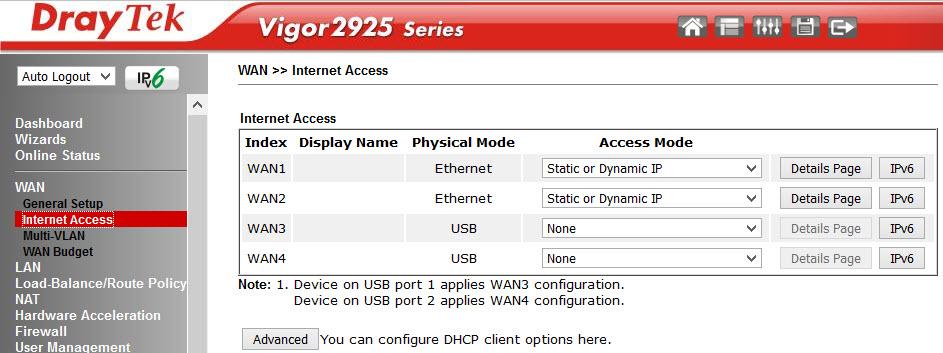
Fig. 10-3
We are moving to Detalils Page WAN 2 , here are the settings for the connection mode, we use a static IP, the first interface is a DHCP client. In addition to the methods we used, you can connect to the Internet using the PPTP / L2TP or PPPoE protocols, also IPv6.
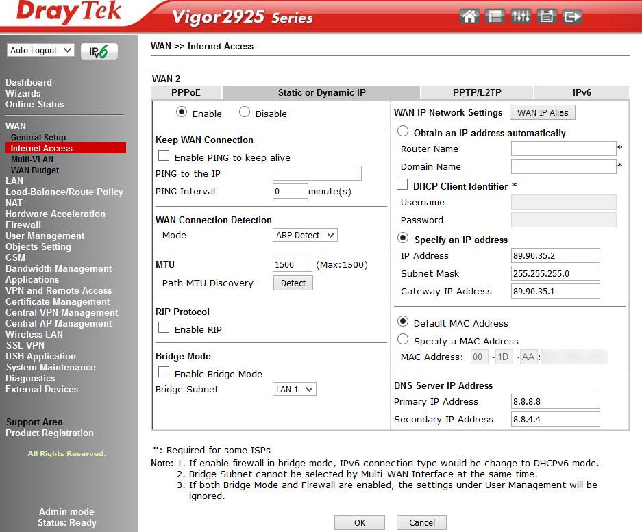
Fig. eleven
The Multi-VLAN submenu allows the administrator to create profiles for a specific physical WAN 1-2 interface and create a bridge with LAN interfaces on the local network to achieve maximum throughput.
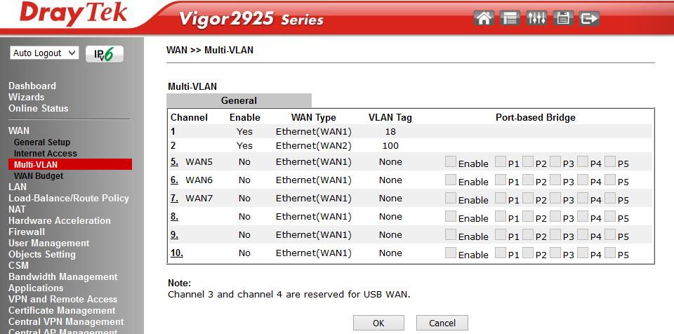
Fig. 12
That is, on the basis of the physical interface WAN 1-2, we create an additional virtual WAN 5-7 in the VLAN specified by us and “bridge” it with the necessary LAN ports 1-3 (port 4 can work only in the NAT mode), optionally, we can assign virtual interface WAN 5-7 IP address manually or receive via DHCP, that is, make it L3. As an example, you can take the forwarding of IPTV traffic from a WAN to a LAN.
The Multi-VLAN submenu is responsible for budgeting or limiting the amount of traffic through WAN interfaces. The traffic budget is allocated for a specific time interval, which is determined by the administrator. After the interval expires, the counter of the consumed traffic is reset and turned on again. The administrator indicates the action that will occur if the traffic budget is spent before the expiration of the time interval, it can be: turn off the interface, send a notification by e-mail or SMS.
Below are images of the interface list and detailed settings, using the example of the WAN1 interface.
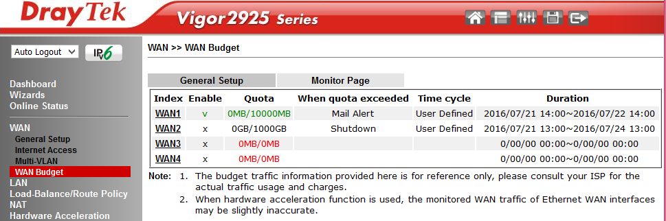
Fig. 12-1
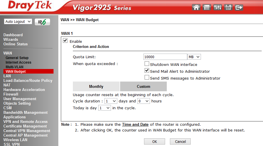
Fig. 12-2
The item is responsible for setting the local network and contains a number of sub-items. The router supports two independent LAN segments with its own settings, the default is 192.168.1.1/24 and 192.168.2.1/24, you can also add one routed network. In both segments, DHCP is enabled which gives IP addresses to connecting user terminals. By the way, the DHCP server can be configured to transfer any additional DHCP options, it is very convenient if there are specialized services on the network, for example, a TFTP server.
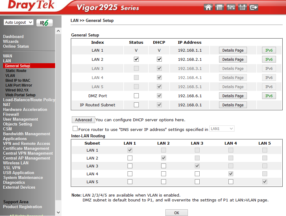
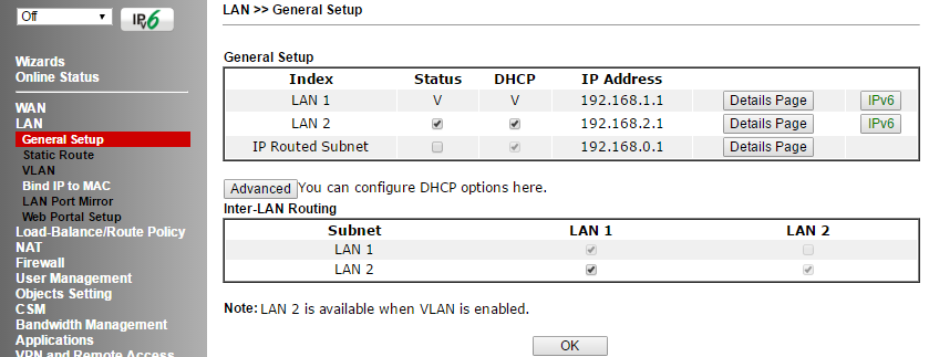
Fig. 13
Additionally, you can enable or disable routing between LAN 1-5 in the Inter-LAN Routing section.
In the next LAN >> Static Route Setup submenu, you can add up to 10 static routes to other networks by IP addresses in LAN subnets 1-5.
The LAN >> VLAN Configuration submenu allows you to combine the specified LAN ports P1-5 with wireless networks SSID 1-4 into one VLAN and optionally add VLAN tags with priorities. When VLAN Tag is enabled, the traffic with tags specified in the VID field will appear on the corresponding LAN ports, tags are not transmitted over wireless networks. In our example, two independent VLANs. VLAN0 includes LAN ports P 2-5 and a wireless network with SSID1 - all this is in LAN 1 segment. VLAN1 includes P1 port and wireless networks with SSID2 and SSID3 - all this is in the LAN 2 segment.
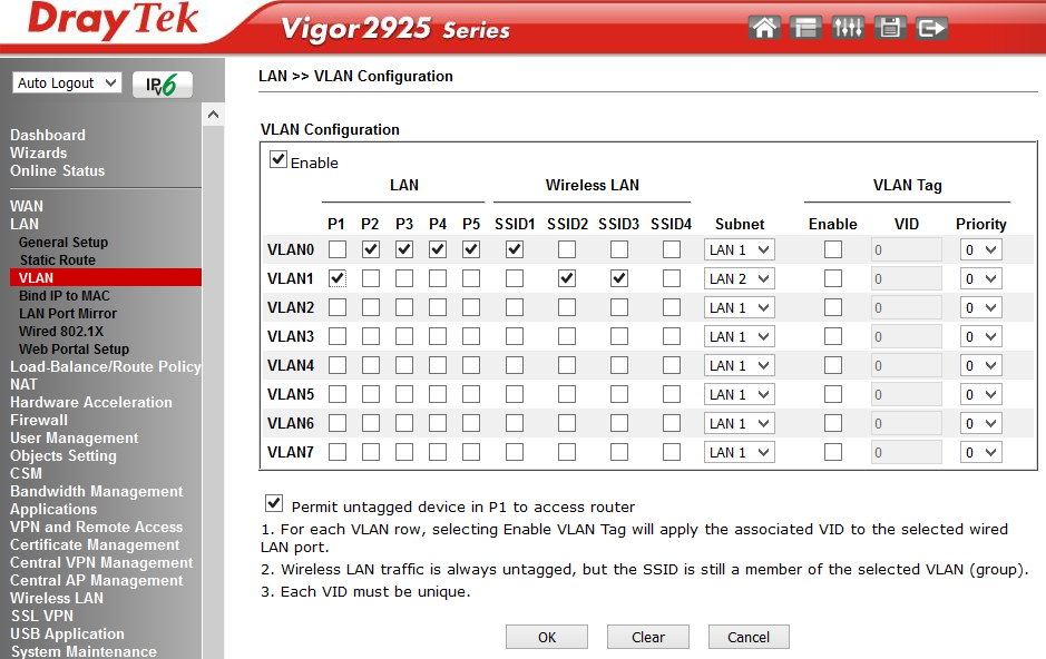
Fig. 14
The router can operate in the mode of creating untagged port-based VLANs, or VLANs based on VID tags.
The next submenu item is LAN >> Bind IP to MAC . Allows you to create lists with matching MAC addresses and IP addresses, if the function allows all assigned IP addresses to MAC addresses can not be changed. Created sheets can be saved to a file and restored to the router configuration from a previously saved file.
In the LAN >> LAN Port Mirror menu, you can enable copying of all traffic from the specified LAN Mirrored port to the receiving Mirror port . This feature is useful for debugging a network using a sniffer or using the Draytek Smart Monitor network monitoring and analysis application; information about this application can be found in the first part of this review. Unlike the Draytek 2912 router, an overview of which in two parts is available by links: part 1 and part 2 , in model 2925, for each port you can specify which traffic to mirror: only incoming Rx, only outgoing Tx, or both.
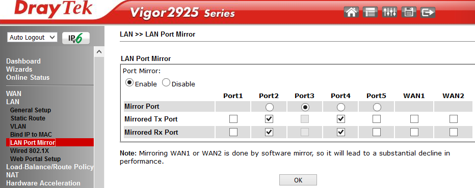
Fig. 15
Wired 802.1X submenu enable 802.1X authentication for any of the 5 LAN ports. Moreover, the function can work in two modes: 802.1X local authentication (configured via the User Profile menu) or through an external RADIUS server.
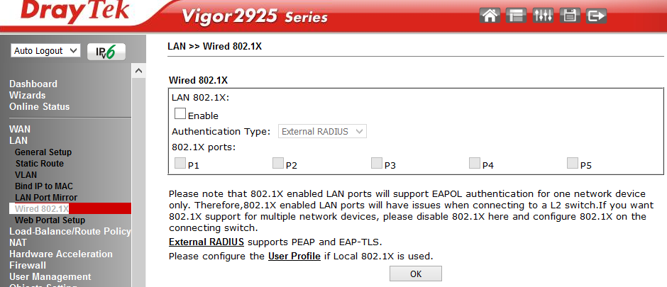
Fig. 15-1
The LAN >> Web Portal Setup submenu allows you to define profiles that are assigned to the LAN or WLAN-wireless network interfaces and specify the URL of the site to automatically redirect the user when you first try to open the web page, after connecting through the interface specified in the profile, for example , SSID1.
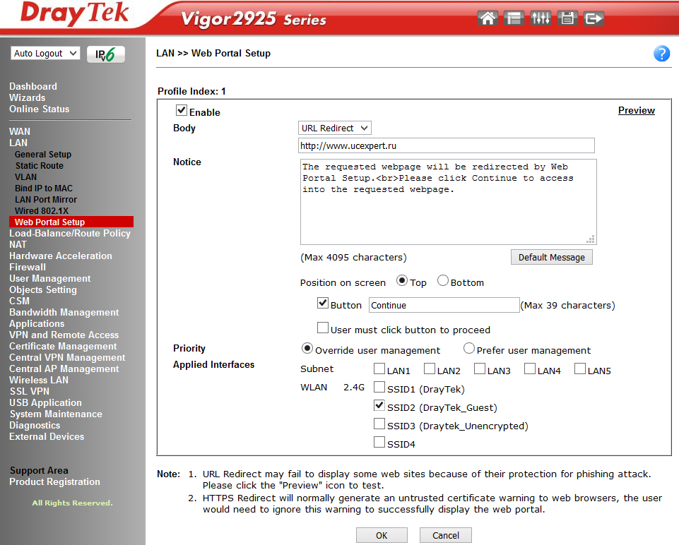
Fig. sixteen
This feature is used for promotional purposes or to notify a user who connects to the Internet through a specific company network.
In the example, when you try to open any web page for the first time, the user will be redirected to the site www.ucexpert.ru , where at the top of the screen there will be a message suggesting the user to click the “Continue” button to continue the web session and go to the desired site.
Below is an example of such a page.
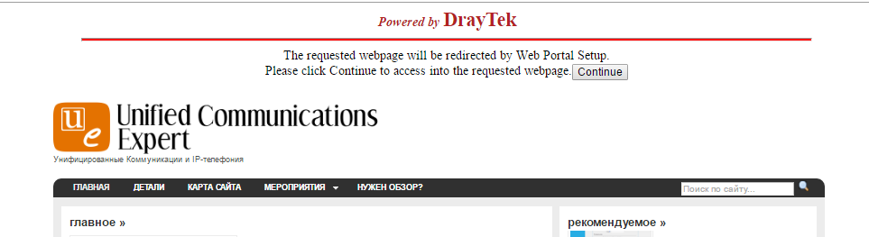
Fig. 17
This menu item contains the General Setup sub-item — direct configuration of load balancing rules and routing policies; and Diagnose , a sub-item for debugging customized rules, where you can simulate the route of one or several packets through the table of customized rules and check the result.
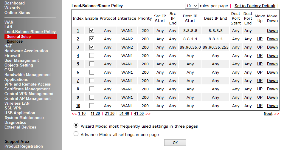
Fig. 18
In the example, packets departing from any LAN IP addresses of the router to IP 8.8.8.8 will pass through WAN1, the second rule works the same way, only for IP destination 8.8.4.4 and the packets will pass through WAN2. The third rule specifies the whole subnet, the fourth rule indicates that all traffic must be sent via WAN1, in case of failure of WAN1, sent to WAN2. Each rule has priority, the lower it is, the earlier the rule is executed.
The following image shows the criteria by which you can set a rule, there are quite a few of them, you can also determine where to send the packet if the rule did not work.
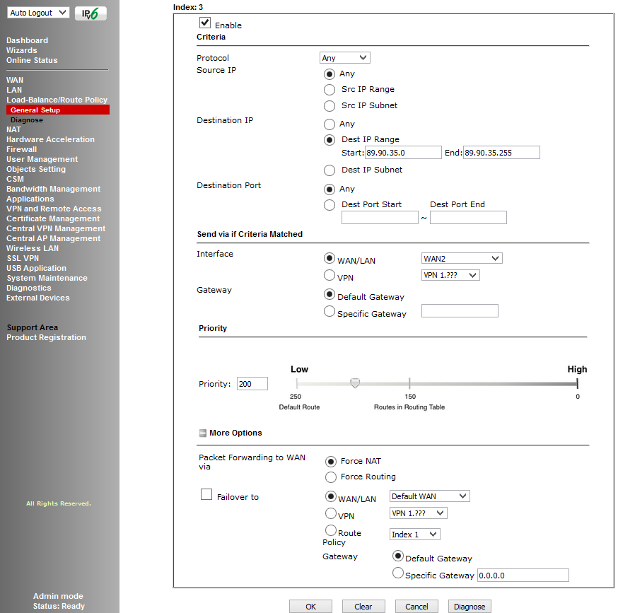
Fig. nineteen
The following figure shows the route diagnostics.
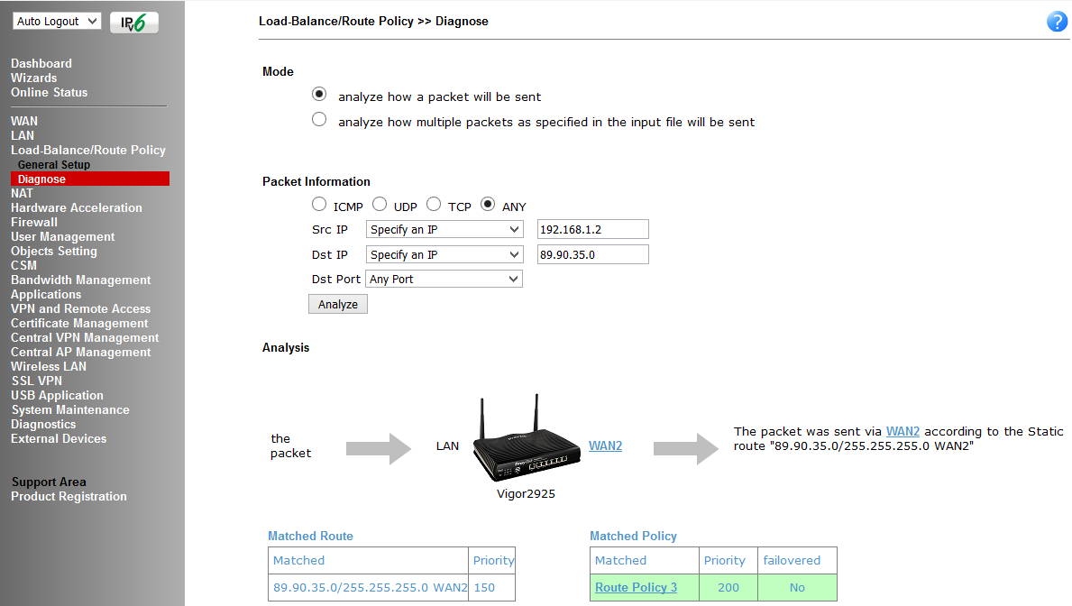
Fig. 20
In the menu, the NAT Address Translation (Network Address Translation) functions are configured; it contains the Port Redirection submenu - port forwarding from the port of the specified WAN interface to the IP address and a port on the LAN network, this may be necessary for FTP servers, mail servers, etc. d.
The DMZ Host submenu allows you to set one DMZ host on the LAN for each of the WAN interfaces.
The Open Ports submenu allows you to keep the specified port ranges open for special applications, such as P2P, and direct them to specific IP addresses on the LAN.
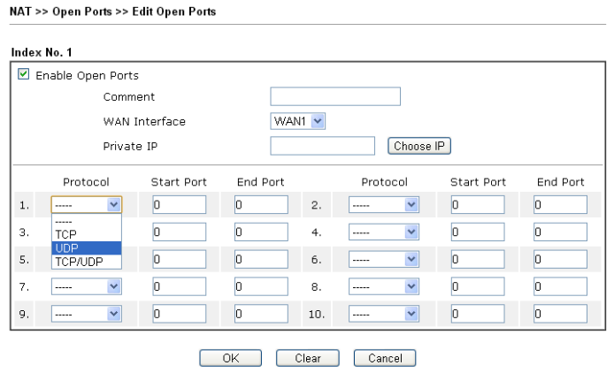
Fig. 21
Port Triggering is a variation of Open Ports . If, after activation of the Open Ports rule, the specified ports are constantly open, then when the Port Triggering rule is applied, the specified ports will open only when the conditions of the rules match, then the ports will close again after a timeout.
The function in the appropriate sub-menu item is defined by a set of rules.
This menu is used to configure hardware acceleration of such functions as Data Flow Monitor - one of the diagnostic submenu items, which displays information about active sessions from IP addresses, Traffic Graph - information from traffic passing through WAN interfaces in the form of graphs, WAN Budget - function budgeting the amount of traffic for a certain period of time. Moreover, the function can be enabled either automatically or manually - specify for which IP address of the host and UDP \ TCP protocol with a range of ports and enable this function.
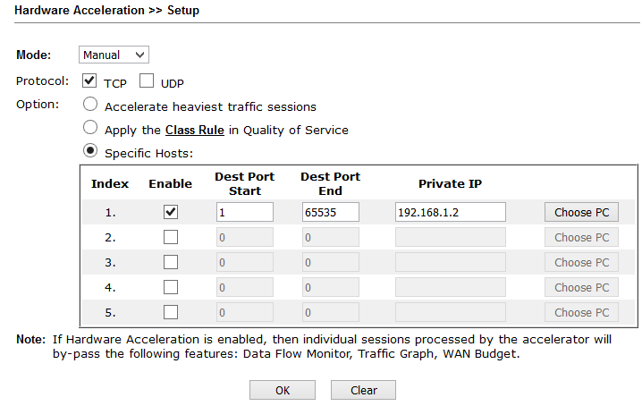
Fig. 21-1
In this menu, global firewall rules are configured, sets and order of traffic inspection rules are specified, and default traffic filtering rules are also specified.
The firewall can be divided into 3 subsystems:
The firewall architecture uses two independent rule sets, Call Filter and Data Filter.
The Call Filter rule set is used for traffic that goes from the local network to the WAN, when there is no active Internet connection (the WAN interface is not active) and before establishing the connection, the traffic passes through the Call Filter rules, if no packets are blocked, the connection is established.
When the WAN interface is active, all packets immediately fall into the Data Filter rule set, and all incoming traffic to the WAN interfaces also falls there.
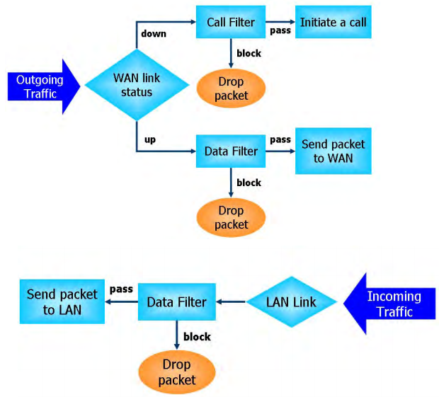
Fig. 22
Firewall rules can specify objects (defined through the Objects Settings menu), such as IP addresses or groups of IP addresses, protocol and port range and their groups, keywords and groups of keywords, file extension profiles, users (certain in the User Management menu) and finally, in the CSM (Content Security Management) menu, define applications, for example, Skype, URLs and even the subject matter of various websites using the Web Content Filter system.
That is, we can work with traffic from the network layer to the application level, plus use the Web Content Filter system for intelligent processing of traffic on the subject of web content, that is, create very broad rules.
Below are the global settings in the Firewall >> General Setup submenu, then the Firewall >> Filter Setup submenu illustrating firewall rulesets, the Firewall >> Filter Setup >> Edit Filter Set submenu illustrating the composition of a particular set of rules.
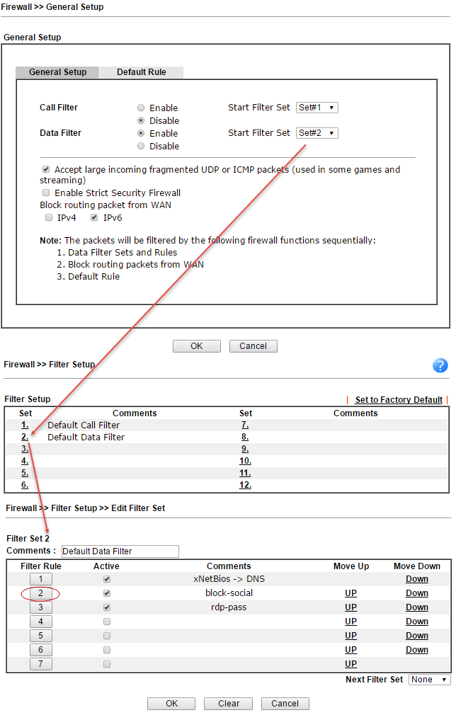
Fig. 23
Now consider a specific rule in from a table called block-social
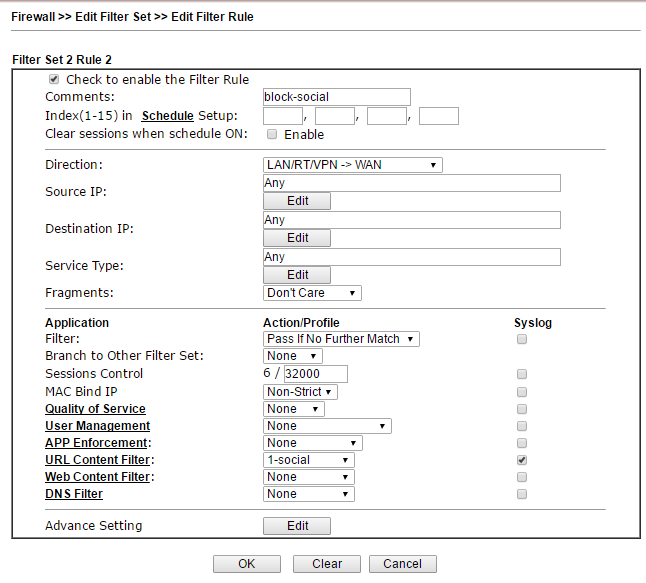
Fig. 24
First, in Schedule, you can specify a schedule when the rule will work, for example, block social networks from 9-30 to 18-00 from Monday to Friday. Next, we specify the direction of traffic checking in the Direction field, any incoming and outgoing IP addresses, the service type can be specified by a specific object in the Objects Setting >> Service Type Object menu, or a set of objects, and is a bundle of protocol type + port or range ports.
Next, in the Filter field we specify the criterion “Pass If No Further Further Match” - packets should be skipped if none of the criteria in the remaining rules matches. If the user turns to a social network, for example, ok.ru, the criterion will match and the package will be blocked. The criterion in this example is a profile in the URL Content Filter , which contains an object - a group including keywords - social network addresses.
Below, I will illustrate the settings when we get to them. In the same way, other criteria are included in the rule, that is, you can add criteria in the firewall rules both at the network level and at the application level, moreover, you can enable Web Content Filter , which runs even higher - at the Web level. content.
Submenu DoS Defense .The router implements detection and automatic protection against DoS attacks, with the traffic intensity threshold metrics after which the event is considered an attack can be manually configured. Also provides for sending notifications about the attack.
A firewall can operate in one of two global modes:
Below are the User Management >> General Setup submenus where you switch between working with IP addresses or working with user profiles.
If everything is clear with work by IP addresses: the administrator assigns an IP address to the user's terminal, which should not be changed and assigns rules for the IP address.
As soon as we switch to User-Based mode, the user must log in, until that moment he will not be able to work on the network, and when opening the browser and trying to access any site, he will be redirected to the login page. To log in, a user profile with the appropriate rights must be contained in the User Management >> User Profile table.
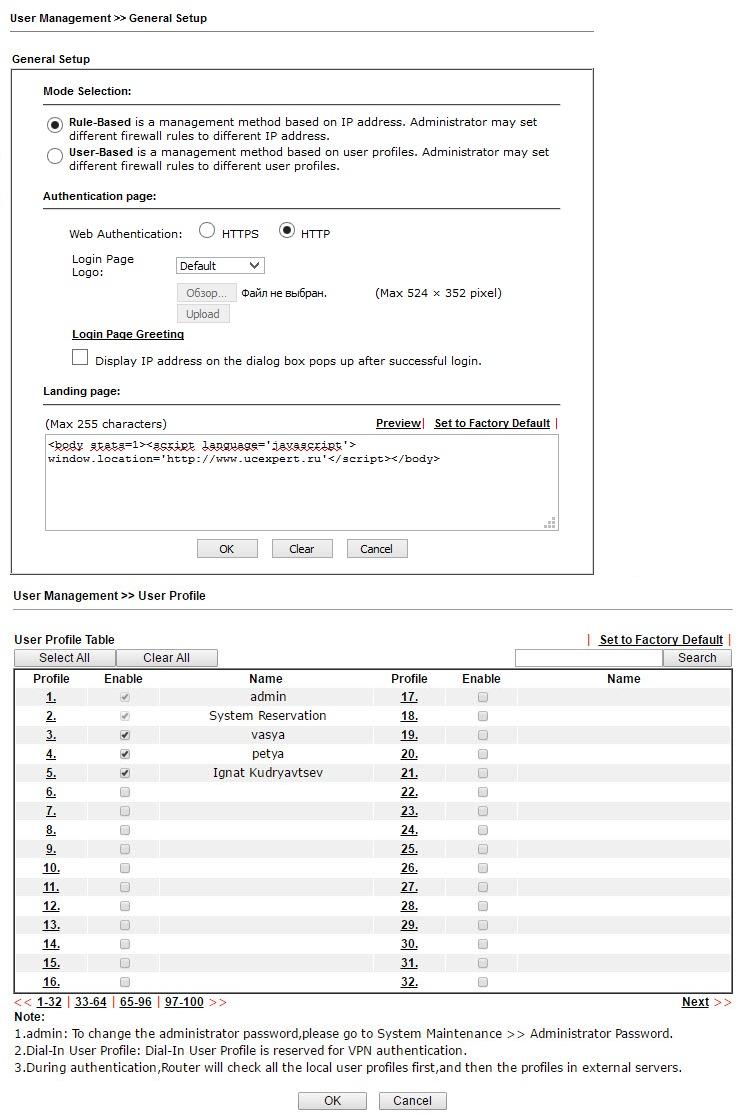
Fig. 25
In the example there is a user profile Ignat Kudryavtsev, open the profile of this user
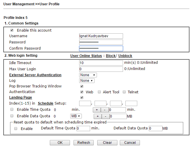
Fig. 26
As you can see, here you can set the timeout for automatic logout in case of idle time, and the restriction on the simultaneous number of logins, enable external authentication using the LDAP or RADIUS protocols. You can also set quotas for time and volume of traffic consumed by the user.
Landing Page - this is the page that the user will see after successful login. You can display a simple message, as in our example: “Login Success!”, Or you can redirect to any website, for example, the company's website. To do this, in the Landing page settings, you need to write a string like:
All settings are described in detail in the user manual. When you open a web browser and try to access any site, the user will be redirected to the login page, after successful login, the message “Login Success!” Will appear and the user will be able to work online.
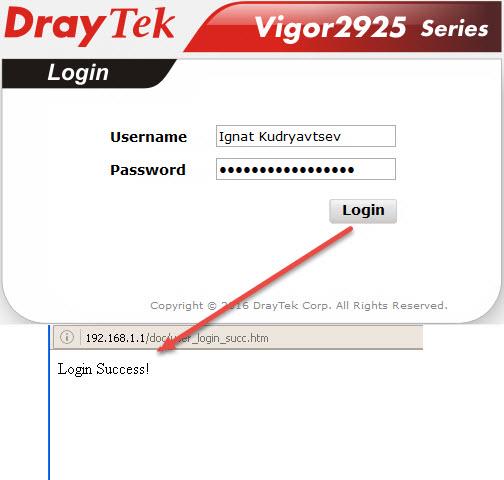
Fig. 27
In the User Group submenu, users can be grouped to then assign the same rules to groups of users, for example, by company department. Submenu User Online Status is used to view the status of users.
Draytek 2925 series routers support firewall with invisible testing of SPI (Stateful Packet Inspection) based on Objects (Object-based), such as: a user (he gets a certain IP during authorization), IP addresses or groups of IP addresses, a protocol and port range and their groups, keywords and keyword groups, file extension profiles. These objects can be used to create firewall rules that can be turned on and off on a schedule.
In the Objects Setting menu, various types of objects are created and grouped.
In the IP Object submenu, objects are created based on the host, range of IP addresses or a subnet. You can also use a specific MAC address for any IP address. In the IP Group submenu, groups are created from IP objects, which can then be used to create firewall rules.
The same for IPv6 Object and IPv6 Group with IP addressing IPv6. In the Service Type Object and Service Type Group submenus, objects are created and grouped based on protocol type, source and destination ports.
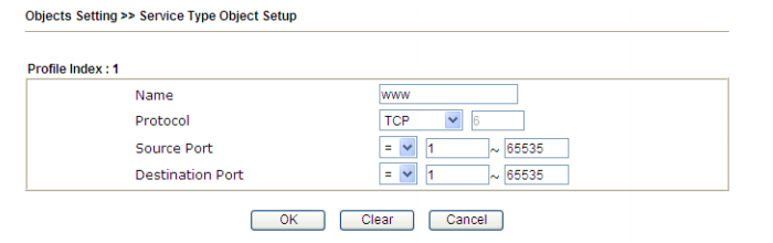
Fig. 28
In the Keyword Object and Keyword Group submenus, objects are created and grouped based on keywords, then these objects can be used to create filtering rules, for example, for the URL Content Filter Profile and DNS Filter Profile in the CSM subsystem. In our example, we block the social networks vk.com twitter.com facebook.com and ok.ru, for this we created two profiles with the names social-nets and social-ok.ru containing the given keywords and added them to the group social-nets- gro submenu Objects Setting >> Keyword Group . Next, we use this group in the CSM >> URL Content Filter Profile .
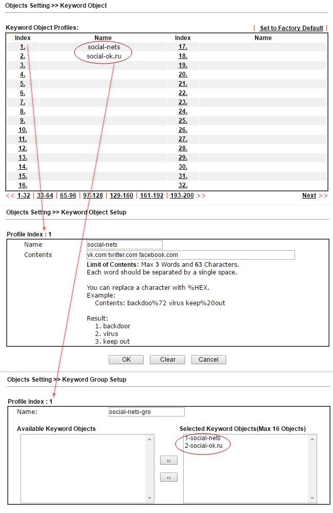
Fig. 29
In the File Extension Object submenu, profiles of extensions are created, files that can be recognized and used in firewall rules. Thus, for example, you can prohibit the download of all compressed files or video files with the specified extensions. The example prohibits the loading of any images. The created profile with the name blk-img will then be used in the CSM profile >> URL Content Filter Profile . We will see this in the example below.
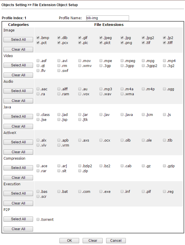
Fig. thirty
The SMS / Mail Service Object and Notification Object submenus allow you to configure up to 10 notification profiles for the Application >> SMS / Mail Alert Service .
CSM (Content Security Management) security system, an application-level firewall subsystem, allows you to block URL links by keywords and content types, for example, Java Applet, Cookies, Active X, you can also block various network applications, for example , IM / P2P or application level protocols, for example, MySQL, SMB, SSH, UltraVPN, the list of services and protocols is quite impressive. It is possible to block DNS by keywords.
In the APP Enforcement Profile submenu, profiles are created for filtering network applications that can use dynamically changing ports, and each such application has its own specifics, for example, Skype.
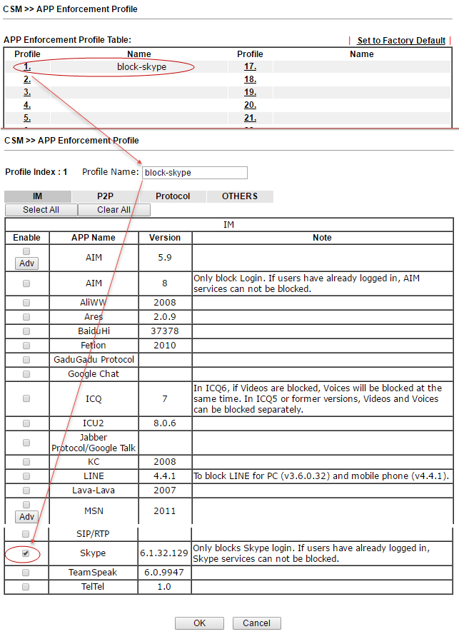
Fig. 31
In the example of the settings for the firewall rule of the Data Filter table above, this rule is indicated.
Submenu URL Content Filter Profile is responsible for filtering web content. The previously created Group / Object Keyword objects are specified here and the URL Access Control function is enabled , then each website address will be searched by keywords. In our example, we added earlier to the created group social-nets-gro containing keywords with the web addresses of social networks.
In the Web Feature section, you can enable cookies, proxy locking and file uploads with those specified in the File Extension Profile , in the example above, we created the 1-blk-img profile.
The created social profile is assigned in the firewall rule in the URL Content Filter field.
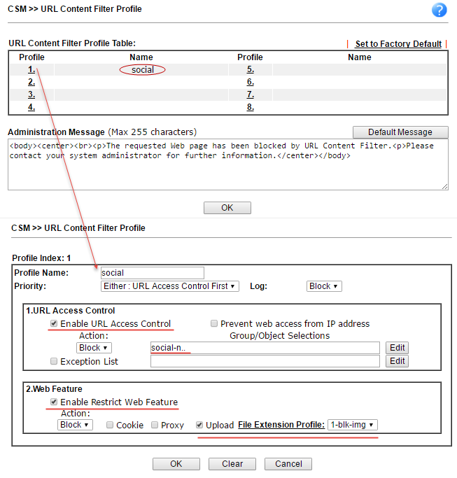
Fig. 32
When the rule works when trying to open, for example, vk.com, the user will see a message from the Administration Message field , an example of the contents of such a field is shown in the previous image.
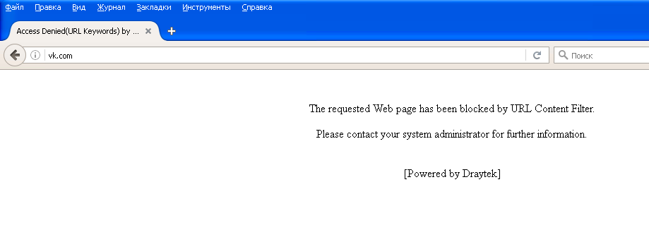
Fig. 33
Submenu Web Content Filter Profile . Another powerful CSM tool is the GlobalView Web Content Filter system. It is designed to filter unwanted content at the thematic level, that is, for example, sites with the theme of porn, crime, gambling, and more. The administrator creates profiles where he specifies the subject of the sites and assigns them to the firewall rules, then indicates what to do if the rule matches, for example, block. Web Content Filter is licensed, but a trial license for testing can be obtained free of charge.
Below is the profile setting by categories:
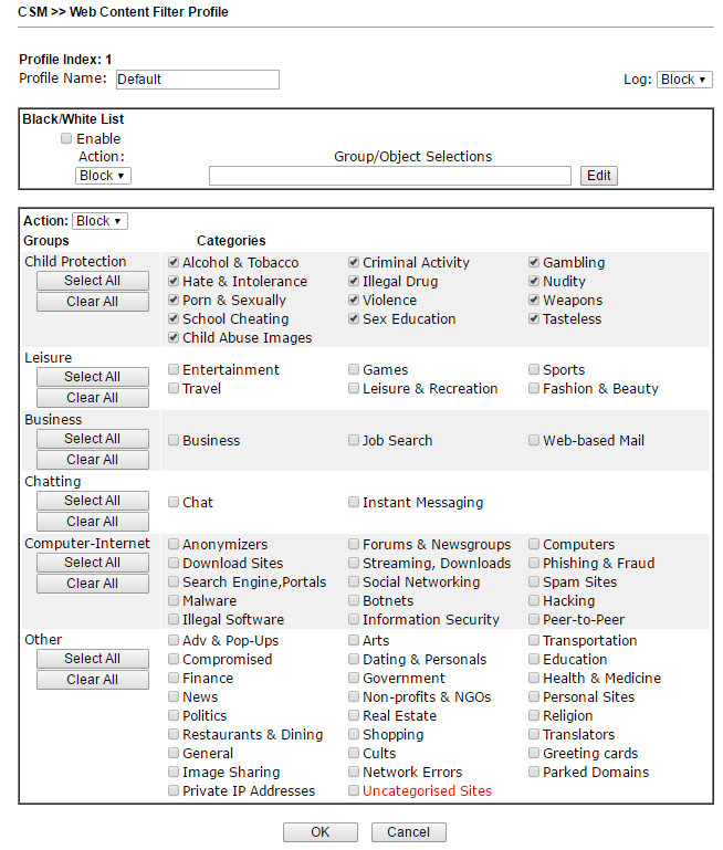
Fig. 34
The DNS Filter Profile subsystem checks and blocks DNS requests for UDP port 53 in accordance with the assigned URL profile Content Filter Profile or Web Content Filter Profile. You can also customize the message that will be displayed to the user when the resource is locked.
The Bandwidth Management >> Sessions Limit submenu is used to limit the number of NATs from sessions with LAN IP addresses that can be simultaneously established. For example, P2P (Peer to Peer) applications typically require multiple simultaneous sessions, and they consume a lot of network resources. You can also limit the number of default sessions from any IP.
The Bandwidth Management >> Bandwidth Limit submenu sets limits on bandwidth utilization for hosts and IP address ranges. Moreover, the operation of the rules can be configured on a schedule, you can separately limit the band for incoming and outgoing traffic.
In the Bandwidth Management >> Quality of Service submenu, the quality of the traffic service is configured. At first, traffic using rules is classified by criteria such as source and destination IP, service type and DiffServ code. Then, each class of traffic is reserved its percentage of the total bandwidth of the specified interface.
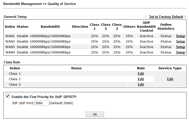
Fig. 35
By the way, prioritization for VoIP traffic is enabled by default.
This menu contains service application settings that help fine-tune individual functions.
For example, in the Schedule submenu, schedule profiles are configured, which are used in various settings of functions and rules of the router; you can create up to 15 entries in the schedule.
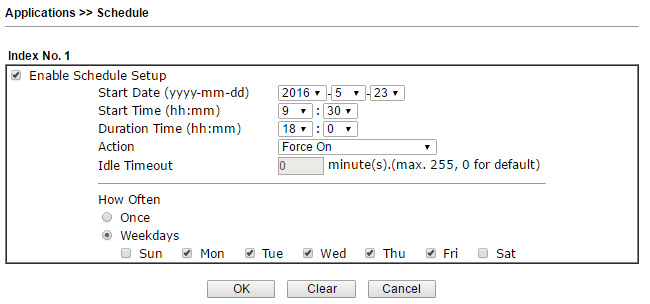
Fig. 36
In the LAN DNS menu , you can specify the correspondence of the IP address and the domain name in the local network. In the RADIUS menu and Active Directory / LDAP, you can optionally enable user authorization on the appropriate submenu server servers. In the IGMP submenu, you can enable IGMP proxying or IGMP snooping for multicast traffic, such as IP TV.
Special attention is given to the High Availability submenu , which serves to configure the redundancy of hardware and software resources of the main router 2925 as backup and backup routers in the event of the main failure. To do this, follow these steps:
1) Enable High Availability Mode — High Availability on the Primary and Standby Routers
2) set the highest Priority ID level on the main router, and lower levels on the backup or backup routers
3) install the same Redundancy Method / Group ID / Authentication Key on the primary and backup routers
4) install the management interface in the same subnet for the main and backup routers.
5) resolve the virtual IP address for each subnet used and set the same virtual IP address on each router.
Backup can work in two modes:
Hot-Standby - this method is suitable for using a single Internet connection:
When HA starts working on routers, the wireless network will automatically be enabled on the primary router, and on the backup router it will automatically turn off. All clients can connect only to the main router.
In addition, a synchronization period is set for configurations from the primary to the backup router. Configuration can be synchronized between 10 router maximum.
Active-Standby - this method is suitable for using multiple Internet connections.
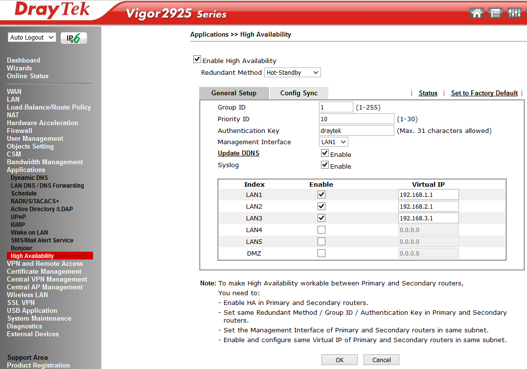
Fig. 36-1
The router supports up to 50 VPN * LAN-to-LAN tunnels to create a secure connection between the organization's networks or create a VPN connection from remote workstations of homeworkers using the SSL / PPTP / IPSec / L2P / L2TPover IPSec protocols. AES / DES / 3DES encryption and IKE authentication provide enhanced security. Using a dual WAN connection allows you to use not only a load balancing scheme, but also redundancy. Therefore, if the main channel of the VPN channel becomes unavailable, it will replace the backup VPN channel.
By the way, the VPN functions in Draytek are very easy to configure. In just a couple of clicks, you can configure both LAN-to-LAN connections and access from remote workstations. Dryatek has its own VPN client to simplify the connection of workplaces, it is called the Draytek Smart VPN Client, the application is available for free download on draytek.com.
The global access VPN protocols are enabled in the Remote Access Control Setup submenu, the Pre-Shared Key for the IKE Authentication method is specified in the IPsec General Setup submenu, and the encryption methods are indicated. For example, specify the key draytek.commmmm
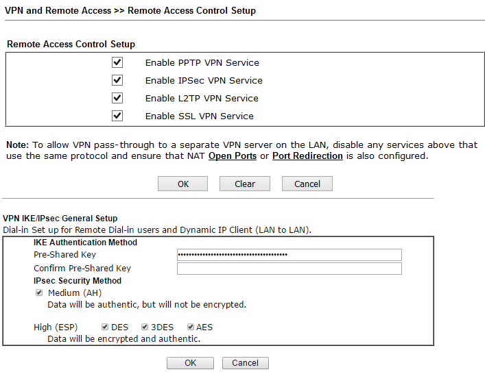
Fig. 37
In the Remote Dial-in User submenu, users who can connect via VPN from their remote locations to the router's LAN are indicated.
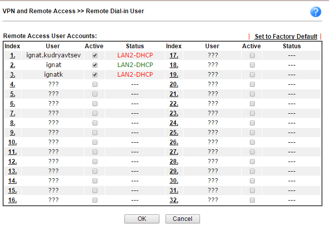
Fig. 38
In the Status list, it is clear that the user ignat is in the status “online”, as it is marked in green.
In the example below, the user ignat connects via PPTP, the second user will connect through the IPSec tunnel using the pre-configured above preshared key = draytek.commmmm.
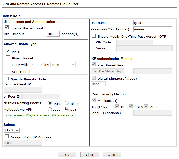
Fig. 39
To connect from the client side, I used the Draytek Smart VPN Client, it is installed and configured in two clicks.
Below is an example for PPTP.
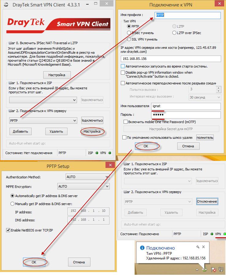
Fig. 40
Similarly, a second VPN client is configured that will dynamically connect using the preshared key that we previously specified in the IPsec General Setup submenu as draytek.commmmm.
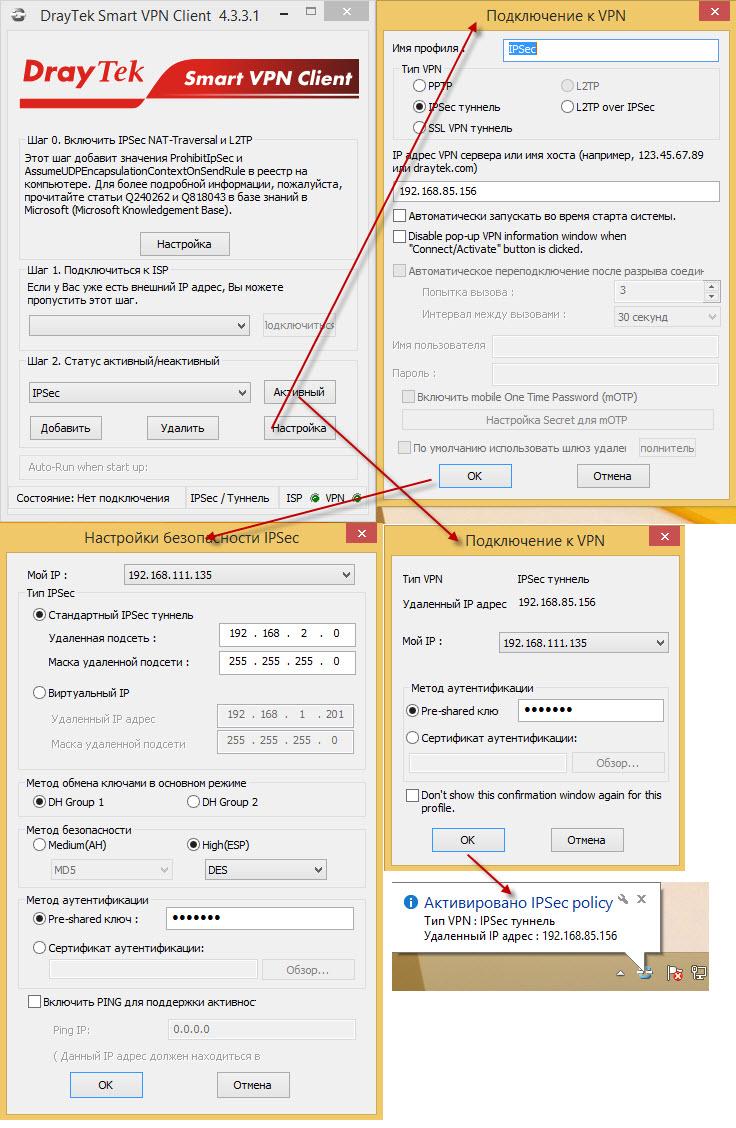
Fig. 42
After successful connection in the Connection Management submenu, we will see active connections.
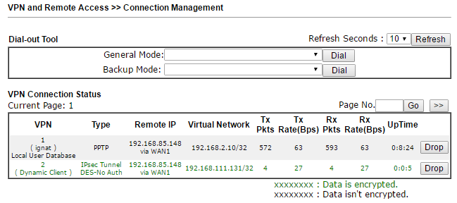
Fig. 43
The LAN to LAN submenu is used to configure VPN connections between two networks. A LAN-to-LAN profile is created, it specifies all settings required for creating a connection: connection type — incoming, outgoing or two-way, VPN protocol — PPTP, L2TP with IPsec Policy or IPsec Tunnel, depending on the protocol, specific settings, for example, login or password or IKE Pre-Shared Key, encryption method and so on. In fact, there are not so many settings, and they are simple in the general case. It specifies which local network the remote side must “see” and which remote network to route traffic through this VPN connection.
After saving the connection settings, the local side will initiate the connection or wait for an incoming connection from the remote side, depending on the settings.
The established connection can also be viewed in the Connection Management submenu.
This menu configures centralized management of VPN connections and some service functions between the Draytek 2925 and remote routers. Setup is very simple - literally in a few steps.
In the CVM >> General Setup submenu, the authorization settings are set, which must then be copied to the remote client device, in our example, via SSL:
https://192.168.85.156:8443/ACSServer/services/ACSServlet , with username = acs and password.
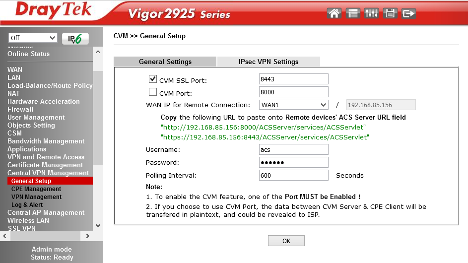
Fig. 43-1
Next, on the remote device in the System Maintenance >> TR-069 submenu, you need to enable it to be managed by entering the settings listed above:
And check the Allow management from the Internet field in the System Maintenance >> Management Setup submenu.
Next, you need to restart the remote router and log in again to the Draytek 2925 web interface.
If the configuration is done correctly, in the Central VPN Management >> CPE Management submenu you will see the device you just added.
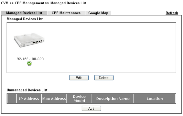
Fig. 43-3
Now the remote router, in our example, this is Vigor2860n +, can be configured from the Draytek 2925 web interface. In addition to setting up and monitoring VPN tunnels, you can update the software version, save and restore the configuration, reboot the remote router. This can be done for one device or for a group of devices. Detailed instructions, including in the format of "how to" is in the user manual.
In the CVM >> VPN Management submenu, you can configure and monitor VPN tunnels.
To do this, you need to click on the remote router you want to configure, and select the type of VPN tunnel. When you click on the type of tunnel, for example, IPSec, it will be created and activated automatically.
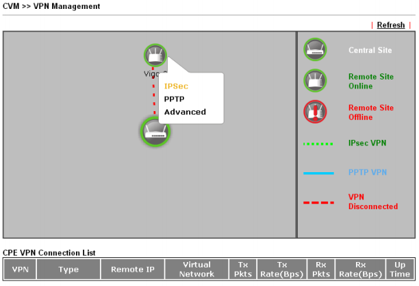
Fig. 43-4
When you click on the Refresh link, you will see the status of the created VPN connection.
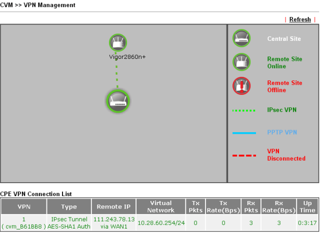
Fig. 43-5
This will create a LAN to LAN profile automatically. If necessary, profiles can be adjusted manually, the only restriction is that you cannot change the name of the VPN profile, as this may cause an error in the operation of the Central VPN Management tool.
This menu is used to automatically detect, configure and service Draytek access points.
In the Central AP Management >> Dashboard submenu, the active access points are displayed. Moreover, the Draytek 2925 automatically finds access points to the network and displays them in this submenu.
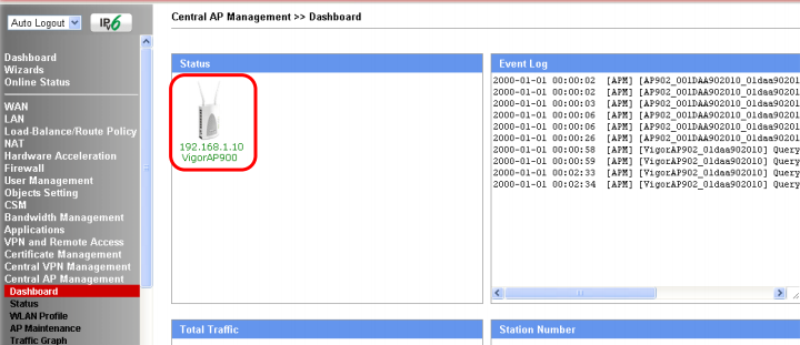
Fig. 43-6
The Central AP Management >> WLAN Profile submenu contains access point settings profiles.
WLAN profile is assigned to the access point, then the access current is automatically adjusted or reconfigured according to the settings specified in the profile.
Fig. 43-7
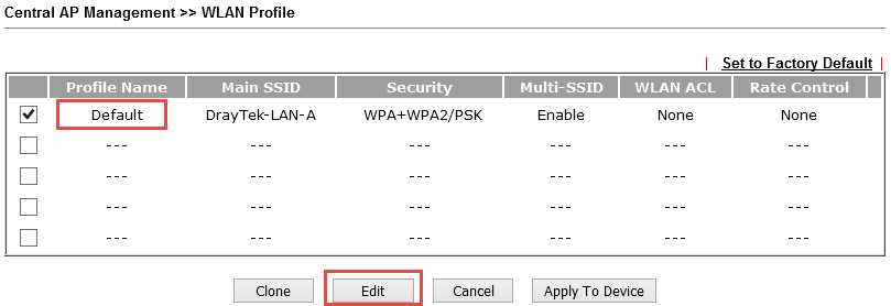
To apply a profile to an access point, tick the profile, then click the Apply To Device button and select the desired device.
Below are the detailed profile settings, the setup takes place in four steps: on the four pages all the settings are consistently set. As you can see from the example, there are a lot of settings.
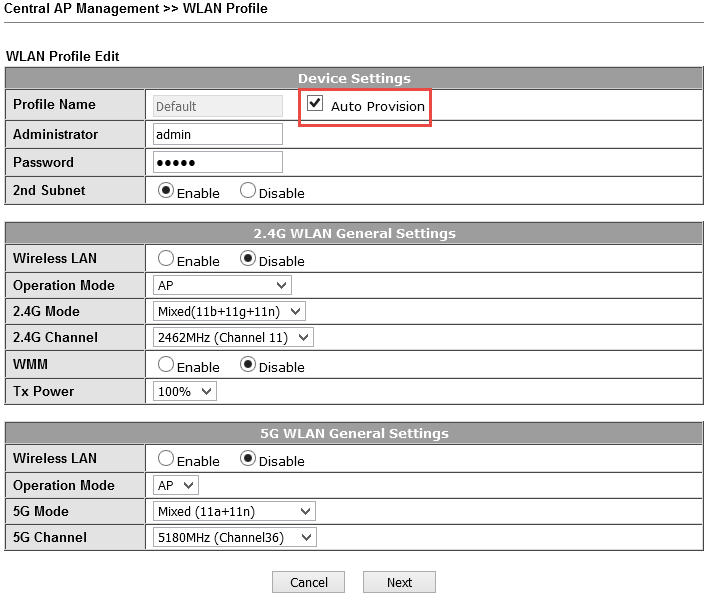
Fig. 43-8
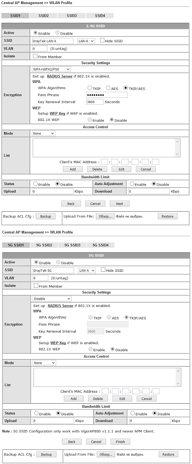
Fig. 43-9
Upon completion of profile editing, on the fourth page, click the Finish button to save all settings made in the profile.
The Central AP Management >> Status submenu displays a list of all access points, their status and detailed settings.
In the Central AP Management >> AP Maintenance submenu, for one access point or group, you can perform the following service functions: saving and restoring configuration, updating firmware, rebooting, resetting to factory settings.
Next, there is a group of submenus for monitoring access points: Traffic Graph - a graphical representation of the total traffic from access points, Rogue AP Detection - detection of "their" and "foreign" access points, Event Log - viewing the event log, Total Traffic - traffic passing through configured LAN segments, Station Number — total number of active wireless clients.
In the Central AP Management >> Load Balance submenu, load balancing is configured by specifying the maximum number of wireless clients on a 2.4GHz and 5GHz network and shaping incoming and outgoing traffic on each wireless client.
The Central AP Management >> Function Support List submenu displays a list of supported functions for the current firmware, depending on the model of the access point. Information on two tabs - for the client and for the server.
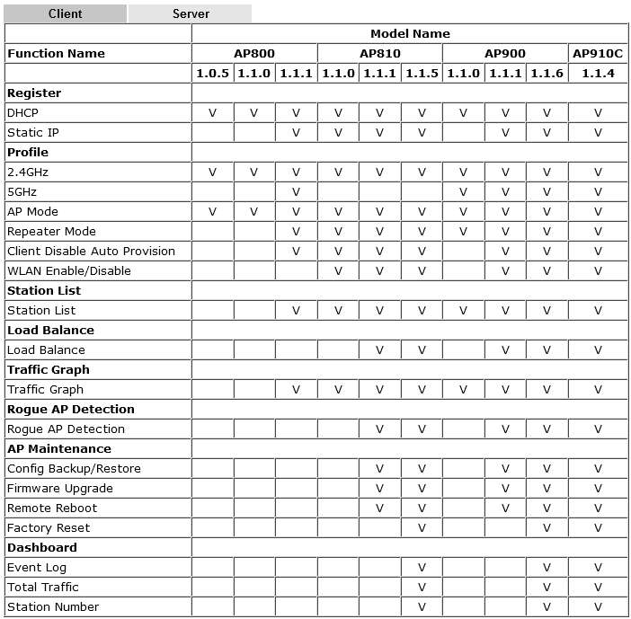
Fig. 43-10
The router, depending on the model, supports 802.11ac, 802.11n, n-plus wireless network and has two or three omnidirectional antennas. The settings of the wireless network functions in the router are large.
The device supports up to 4 independent wireless networks with their own settings, and for each of the networks you can limit the maximum bandwidth for outgoing and incoming traffic, and also enable the schedule according to which these restrictions will work.
Below to illustrate the settings are the General Setup and Security Settings submenus. The settings are very visual.
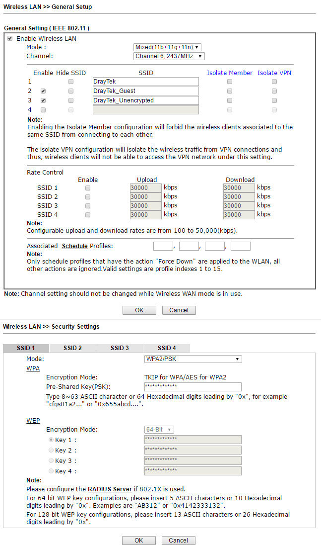
Fig. 44
For each of the 4x wireless networks, their own security settings are configured, including MAC address filters. For each network, you can enable the Wi-Fi usage quota based on the MAC address and the timeout for re-quota provisioning.
Below is the Station List submenu , which shows the currently connected wireless terminals.
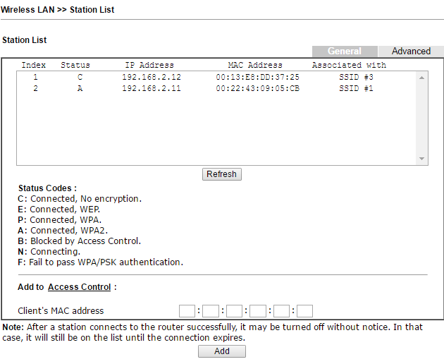
Fig. 45
In addition, in the Access Control submenu, you can enable the MAC address filter, and create both white and black lists of MAC addresses. Lists can be saved to a file on a computer or downloaded from a file, if necessary.
The Advanced Setting submenu contains radio channel fine tuning, for example, outgoing signal power, operating mode, channel width, fragment length, and others.
Wireless also supports configuration via WPS (Wi-Fi Protected Setup) and WDS settings, which can be found in the corresponding sub-items of the Wireless LAN menu.
In the Draytek 2925 router, you can configure application access via SSL VPN using a standard web browser.
This method provides certain advantages over traditional VPNs, including the absence of the need for additional software, for example, a VPN client to create a secure connection, another advantage: fewer restrictions on data encryption using SSL compared to traditional SSL.
The service is globally enabled by installing a checkbox for the option Enable SSL VPN Service in the VPN and Remote Access >> Remote Access Control Setup submenu .
Further, in the SSL VPN >> General Setup submenu, it is indicated on which WAN interfaces the service is available and on which port. The default is 443. I advise you to change it to another, in order to avoid a conflict with the standard port for Draytek web management.
Further, by analogy with the above VPN settings PPTP and PPTP, in the SSL VPN >> Remote Dial-in User submenu, you need to configure users who can use SSL VPN by setting the checkbox for the SSL Tunnel option .
Now in the SSL VPN >> SSL Web Proxy submenu, you must specify the URL addresses for which you need to open access via SSL VPN. In the SSL VPN >> SSL Application menu, you can select the application and host and port, for example, RDP on 192.168.1.50:50389, which will be forwarded via SSL VPN.
After saving all the settings, the user opens a web browser, enters the IP and port on the WAN interface, where the VPN SSL service is running, authenticates with the administrator's login and password, then goes to the page with VPN SSL services available to him.
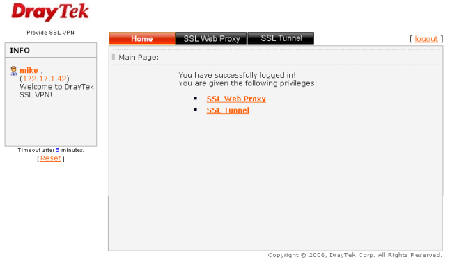
Fig. 45-1
In the SSL VPN >> Online Status submenu, active connections will be displayed.
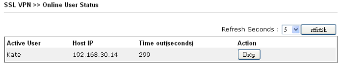
Fig. 45-2
The router has a USB port that can be used in three different modes. First, connect a USB 3G / 4G modem to reserve an Internet connection or as a basic Internet connection if there are no other ways to connect to the Internet.
Secondly, connect the USB printer to the router, which becomes the print server and users will be able to use it by setting up access to it over the network.
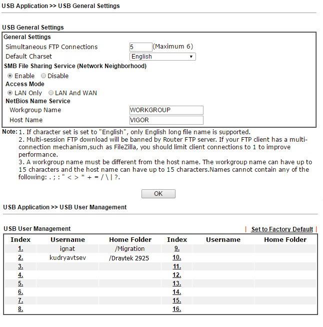 Fig. 46
, , USB- FTP SMB. .
, USB Device Status, , USB- 8 , .
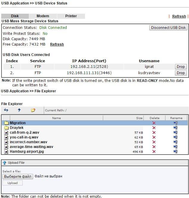
. 47
-, USB- FTP NetBios/SMB. Modem Support List, LAN SMB Client Support List.
3G/4G , Modem Printer USB Device Status .

. 47-1
. User Administrator, TR-069 . Configuration Backup . Configuration Backup SysLog, . , .

. 48
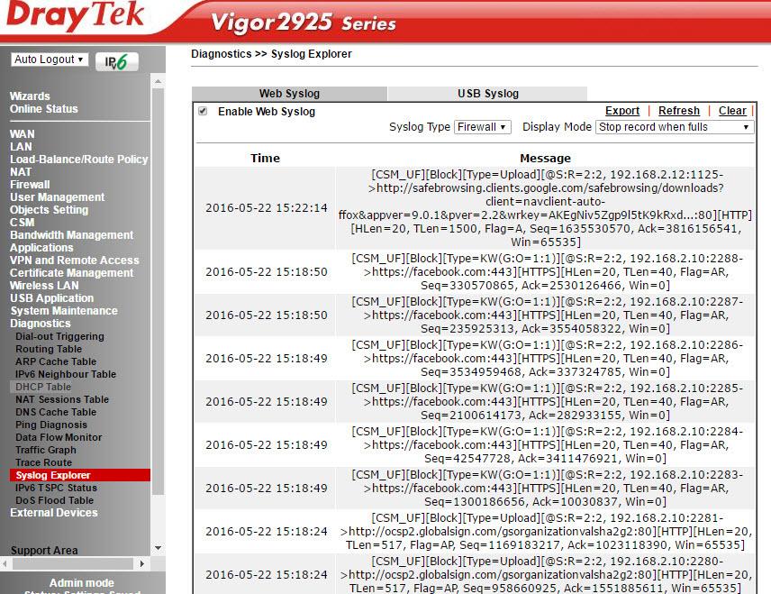
, Draytek syslog . Draytek Syslog. .
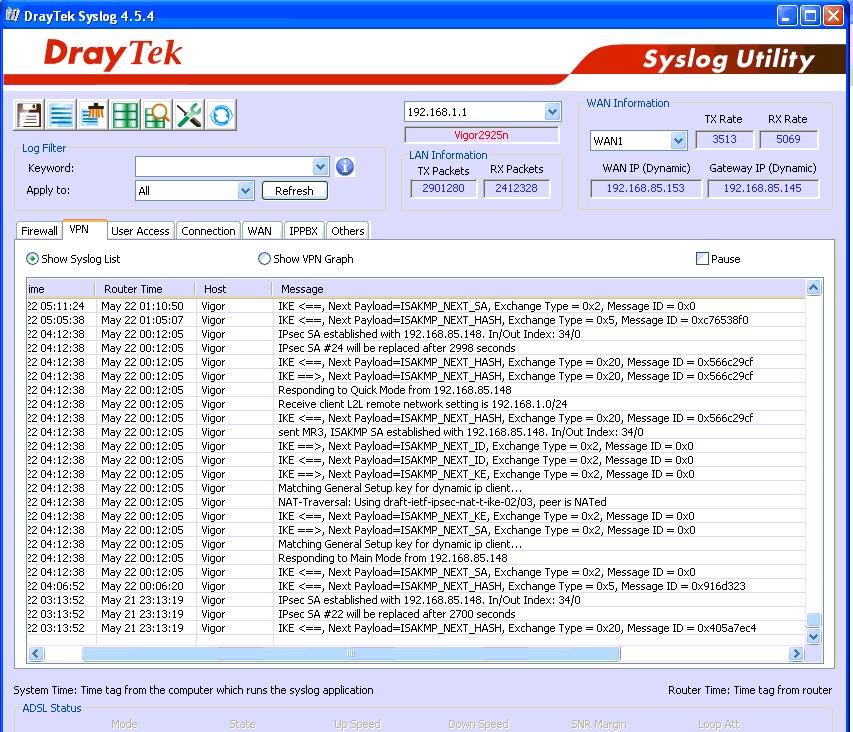
. 49
Management . , , WAN .
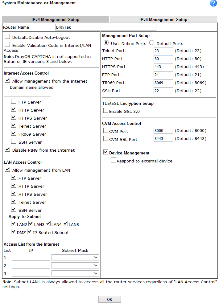
. 50
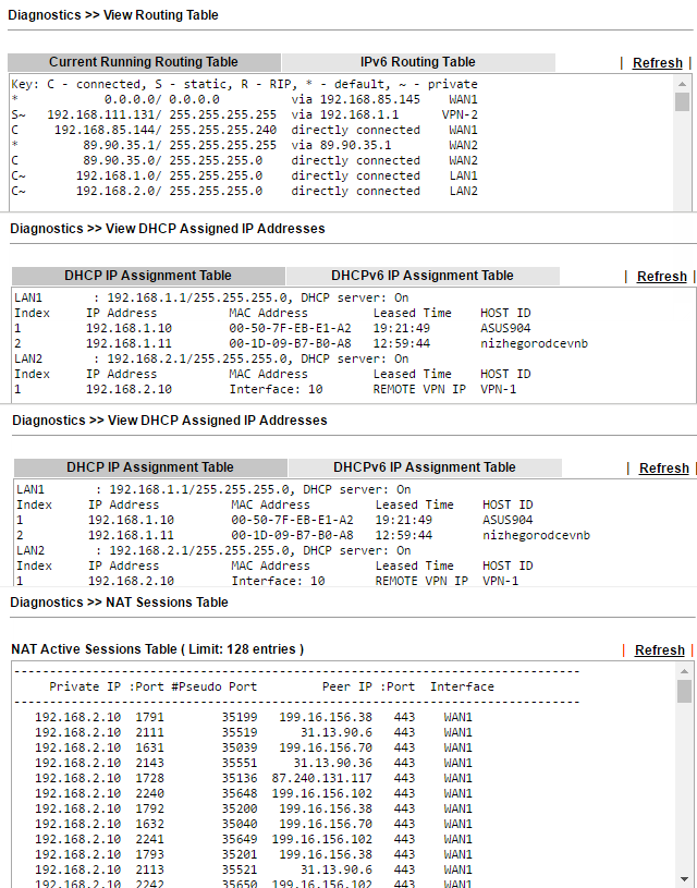
, — .
Routing Table , ARP Cache Table MAC- , DHCP-Table DHCP-, NAT- DNS-.
. 51
Ping Traceroute . , : VPN, Firewall, WAN .
. 52
Traffic Graph , , WAN .
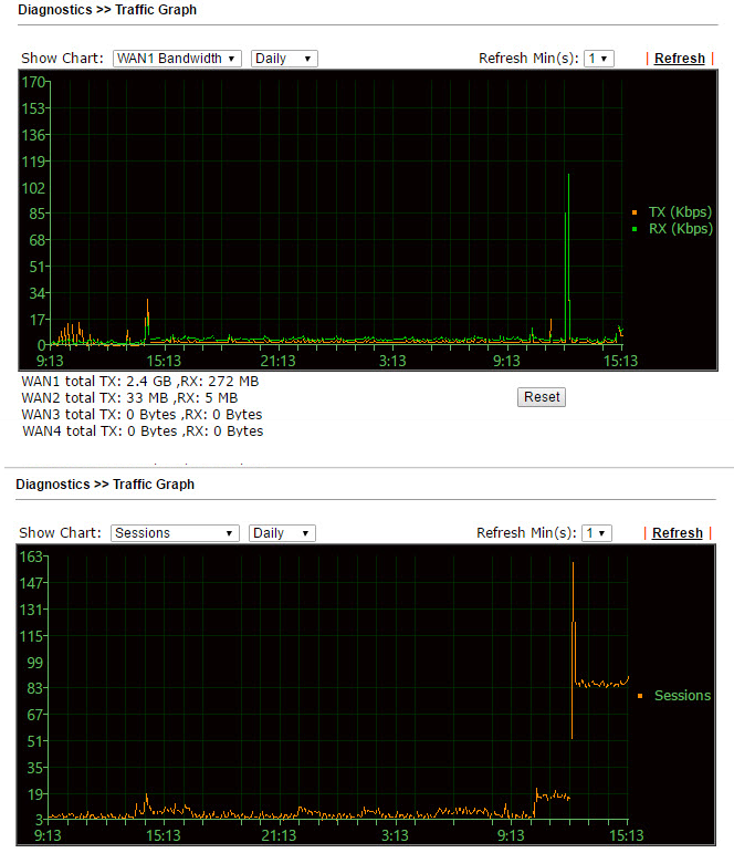
. 53
Draytek 2925 2925n , . , , , , Draytek 2925n, , , , VPN-, NAS- . Drayatek 2925 – , 6 , VoIP.
, , , – . Draytek VigorACS SI, , . Draytek Smart Monitor, , . 2925 Central VPN Management VPN- Draytek 2925 . VPN- .
, Dryatek 2925 AP Central Management, - , .
High Availability, 2925 «» Draytek, , WAN .
, , . .
, , , WAN LAN, , , VPN, , NAT , USB, . SSL VPN, High Availability, VPN- Central AP Management Central VPN Management. , , , Draytek .
Draytek 2925n , , -, CLI TR-69. , VigorACS SI Smart Monitor , . «», SMB+ , «» 100\ WAN- -. , . , , , .
The results unambiguously demonstrate the wide capabilities of the router, coupled with the “gigabit”, which may be needed by an SMB and SMB + enterprise level or a small branch of a large company that have “outgrown” 100Mbit / s network connections and need hundreds of megabits on the local network and WAN interfaces to the ISP. Therefore, the device has great potential for use in resource-intensive corporate networks. Load testing, the results of which you can see in the first part of the review, showed good results. The first part of the review is available at this link.
In this part of the review, we will take a closer look at the device’s web interface, learn about its features and an example of setting up such functions and interfaces as WAN and LAN, Load balancing, wireless network, VPN (PPTP, IPSec and SSL), firewall, NAT, special tools for auto configuration and centralized management of access points - Central AP Management and VPN connections on remote routers –Central VPN Management, bandwidth control, a function of creating a cluster of high availability from several routers, as well as USB functions, diagnostics and installation utoringa router.
Below is a general wiring diagram of the router.
')
Fig. 0
Fig. 0-1
I pay attention that all Ethernet all ports of WAN and LAN are "gigabit".
By default, the router has an open wireless network called Draytek and a DHCP server, you can connect to it or use one of the LAN ports.
After connecting to the router from the PC and successfully obtaining the IP address from the 192.168.1.0/24 network, open its web interface, to do this, in the web browser, dial the default LAN IP 192.168.1.1, Username: admin, password: admin. I recommend immediately changing the password to a more secure one.
Fig. one
We get to the “ Online Status” menu , where the main information about the device is displayed.
Fig. 2
Below, in the image, the “ Dashboard” menu is presented , in which the router’s connection to the WAN, LAN and wireless WLAN networks is clearly displayed. Simply and clearly
Fig. 2-1
I note that the firmware version 3.7.8.2_R is preinstalled on routers shipped to Russia, this firmware differs from the usual one in that it does not have encryption other than the PPTP protocol, it looks like this:
Fig. 3
If this is not enough, you can install a full-fledged firmware by downloading it from the Draytek.com website in the Supports section -> Downloads -> Firmware - Vigor2925 Series .
I chose the latest 3.8.2.3 and downloaded it, then, unzip it, in the web interface of the router, open System Maintenance >> Firmware Upgrade and specify the file v2925_3823.all, then click "Upgrade" .
Fig. four
After a successful update, restart the router and get the latest firmware without any restrictions.
For clarity, below is an image of the network scheme for the Draytek 2925n router, for the example of which we will consider its web interface, as well as some examples of setting functions.
Fig. 4-1
To connect to the Internet, we use two WAN interfaces with several routing rules. In case of a failure on the first channel, the traffic will automatically go through the backup.
We use two subnets: LAN0 = 192.168.1.0 / 24 and LAN1 = 192.168.2.0 / 24. And three wireless networks with SSID: DrayTek, DrayTek_Guest and DrayTek_Unencrypted. They are integrated through VLAN settings with wireless networks. Remote clients can connect via VPN using Smart VPN Client and PPTP and IPSec protocols. For the SmartMonitor application, mirroring is enabled from the LAN ports.
In general, regardless of the model of the Draytek router, the menu structure has a similar organization, you can not find any functions, or discover more of them than in another model or firmware version, but the structure remains unchanged. On the left is a block of global menu items structured by router subsystems: Wizards, settings for wired network interfaces WAN and LAN, then a firewall settings block (Firewall, Objects Settings, CSM) and User Management, then a settings block special router applications (Applications). Then there are two menu items responsible for centralized management of Draytek - Central AP Management wireless points and centralized VPN management on Draytek - Central VPN Management routers. Then the VPN settings block, followed by the menu for setting up a wireless network (Wireless LAN), a separate menu for setting the USB port (USB Application), and finally the menu of service functions (System Maintenance) and the diagnostics menu of the router (Diagnostics).
All items are structured simply and logically, in accordance with the network functions, without any specific and confusing logic.
Each global menu item includes one or more sub-items. Consider the main menu items, since the router has a configuration corresponding to the network scheme that was presented above, as we review the new menu items, it will become clear how these or other network functions are configured.
Wizards Menu
Here are the settings wizards that allow you to configure the main functions of the router with a few clicks. They are a chain of several dialog boxes, the last window displays a listing of all the settings made and the “Finish” button to apply them. It seemed to me that the data of the wizard for very lazy administrators, as well as without them, setting up the basic functions on the router is easy.
Quick Start Wizard - used to quickly configure the connection WAN 1-3 interfaces.
Service Activation Wizard - activates an intelligent thematic filter Web Content Filter .
The following wizards of the VPN Client Wizard and the VPN Server Wizard seemed interesting to me, with the help of them it is easy to configure the VPN in the LAN-to-LAN and Remote Dial-in User modes, activate the service and register the users. Below, an example of 3 steps to add and activate a VPN user.
We chose PPTP, then you need to configure the client-side, we will use the Draytek Smart VPN client. Let's go back to the VPN settings in the VPN and Remote Access menu.
Fig. five
Fig. 6
Fig. 7
Wireless Wizard Wizard is used for initial configuration of a wireless network. Below is the final window at the completion of the wizard.
Fig. eight
In a couple of clicks, the wireless network is set up.
Menu Online Status
The next menu item contains two subitems: the first Physical Connection shows the physical status of the interfaces LAN, WAN 1-3 and link-level counters, the same thing, but only for virtual interfaces can be seen in the Virtual WAN menu.
Fig. 9
More detailed information on the system status can be found in System Maintenance -> System Status .
WAN menu
In this menu, all settings related to the connection of the router to the Internet providers are made. In our example, WAN 1 and 2 are active:
Fig. 10-1
Load balance mode setting is available when two or three WAN interfaces are used simultaneously. We use Auto Weigh mode; in this mode, the router automatically distributes the load. The WAN 3 interface can be used when connecting a 3 / 4G modem.
Below is the detailed configuration of the WAN 2 interface, we use load balancing mode.
Fig. 10-2
In the Internet Access submenu, the interfaces are configured directly.
Fig. 10-3
We are moving to Detalils Page WAN 2 , here are the settings for the connection mode, we use a static IP, the first interface is a DHCP client. In addition to the methods we used, you can connect to the Internet using the PPTP / L2TP or PPPoE protocols, also IPv6.
Fig. eleven
The Multi-VLAN submenu allows the administrator to create profiles for a specific physical WAN 1-2 interface and create a bridge with LAN interfaces on the local network to achieve maximum throughput.
Fig. 12
That is, on the basis of the physical interface WAN 1-2, we create an additional virtual WAN 5-7 in the VLAN specified by us and “bridge” it with the necessary LAN ports 1-3 (port 4 can work only in the NAT mode), optionally, we can assign virtual interface WAN 5-7 IP address manually or receive via DHCP, that is, make it L3. As an example, you can take the forwarding of IPTV traffic from a WAN to a LAN.
The Multi-VLAN submenu is responsible for budgeting or limiting the amount of traffic through WAN interfaces. The traffic budget is allocated for a specific time interval, which is determined by the administrator. After the interval expires, the counter of the consumed traffic is reset and turned on again. The administrator indicates the action that will occur if the traffic budget is spent before the expiration of the time interval, it can be: turn off the interface, send a notification by e-mail or SMS.
Below are images of the interface list and detailed settings, using the example of the WAN1 interface.
Fig. 12-1
Fig. 12-2
LAN menu
The item is responsible for setting the local network and contains a number of sub-items. The router supports two independent LAN segments with its own settings, the default is 192.168.1.1/24 and 192.168.2.1/24, you can also add one routed network. In both segments, DHCP is enabled which gives IP addresses to connecting user terminals. By the way, the DHCP server can be configured to transfer any additional DHCP options, it is very convenient if there are specialized services on the network, for example, a TFTP server.
Fig. 13
Additionally, you can enable or disable routing between LAN 1-5 in the Inter-LAN Routing section.
In the next LAN >> Static Route Setup submenu, you can add up to 10 static routes to other networks by IP addresses in LAN subnets 1-5.
The LAN >> VLAN Configuration submenu allows you to combine the specified LAN ports P1-5 with wireless networks SSID 1-4 into one VLAN and optionally add VLAN tags with priorities. When VLAN Tag is enabled, the traffic with tags specified in the VID field will appear on the corresponding LAN ports, tags are not transmitted over wireless networks. In our example, two independent VLANs. VLAN0 includes LAN ports P 2-5 and a wireless network with SSID1 - all this is in LAN 1 segment. VLAN1 includes P1 port and wireless networks with SSID2 and SSID3 - all this is in the LAN 2 segment.
Fig. 14
The router can operate in the mode of creating untagged port-based VLANs, or VLANs based on VID tags.
The next submenu item is LAN >> Bind IP to MAC . Allows you to create lists with matching MAC addresses and IP addresses, if the function allows all assigned IP addresses to MAC addresses can not be changed. Created sheets can be saved to a file and restored to the router configuration from a previously saved file.
In the LAN >> LAN Port Mirror menu, you can enable copying of all traffic from the specified LAN Mirrored port to the receiving Mirror port . This feature is useful for debugging a network using a sniffer or using the Draytek Smart Monitor network monitoring and analysis application; information about this application can be found in the first part of this review. Unlike the Draytek 2912 router, an overview of which in two parts is available by links: part 1 and part 2 , in model 2925, for each port you can specify which traffic to mirror: only incoming Rx, only outgoing Tx, or both.
Fig. 15
Wired 802.1X submenu enable 802.1X authentication for any of the 5 LAN ports. Moreover, the function can work in two modes: 802.1X local authentication (configured via the User Profile menu) or through an external RADIUS server.
Fig. 15-1
The LAN >> Web Portal Setup submenu allows you to define profiles that are assigned to the LAN or WLAN-wireless network interfaces and specify the URL of the site to automatically redirect the user when you first try to open the web page, after connecting through the interface specified in the profile, for example , SSID1.
Fig. sixteen
This feature is used for promotional purposes or to notify a user who connects to the Internet through a specific company network.
In the example, when you try to open any web page for the first time, the user will be redirected to the site www.ucexpert.ru , where at the top of the screen there will be a message suggesting the user to click the “Continue” button to continue the web session and go to the desired site.
Below is an example of such a page.
Fig. 17
Menu Load-Balance / Route Policy
This menu item contains the General Setup sub-item — direct configuration of load balancing rules and routing policies; and Diagnose , a sub-item for debugging customized rules, where you can simulate the route of one or several packets through the table of customized rules and check the result.
Fig. 18
In the example, packets departing from any LAN IP addresses of the router to IP 8.8.8.8 will pass through WAN1, the second rule works the same way, only for IP destination 8.8.4.4 and the packets will pass through WAN2. The third rule specifies the whole subnet, the fourth rule indicates that all traffic must be sent via WAN1, in case of failure of WAN1, sent to WAN2. Each rule has priority, the lower it is, the earlier the rule is executed.
The following image shows the criteria by which you can set a rule, there are quite a few of them, you can also determine where to send the packet if the rule did not work.
Fig. nineteen
The following figure shows the route diagnostics.
Fig. 20
NAT menu
In the menu, the NAT Address Translation (Network Address Translation) functions are configured; it contains the Port Redirection submenu - port forwarding from the port of the specified WAN interface to the IP address and a port on the LAN network, this may be necessary for FTP servers, mail servers, etc. d.
The DMZ Host submenu allows you to set one DMZ host on the LAN for each of the WAN interfaces.
The Open Ports submenu allows you to keep the specified port ranges open for special applications, such as P2P, and direct them to specific IP addresses on the LAN.
Fig. 21
Port Triggering is a variation of Open Ports . If, after activation of the Open Ports rule, the specified ports are constantly open, then when the Port Triggering rule is applied, the specified ports will open only when the conditions of the rules match, then the ports will close again after a timeout.
The function in the appropriate sub-menu item is defined by a set of rules.
Hardware Acceleration menu
This menu is used to configure hardware acceleration of such functions as Data Flow Monitor - one of the diagnostic submenu items, which displays information about active sessions from IP addresses, Traffic Graph - information from traffic passing through WAN interfaces in the form of graphs, WAN Budget - function budgeting the amount of traffic for a certain period of time. Moreover, the function can be enabled either automatically or manually - specify for which IP address of the host and UDP \ TCP protocol with a range of ports and enable this function.
Fig. 21-1
Firewall menu
In this menu, global firewall rules are configured, sets and order of traffic inspection rules are specified, and default traffic filtering rules are also specified.
The firewall can be divided into 3 subsystems:
- User-configurable IP filter based on the Call Filter / Data Filter rule sets
- Stateful Packet Inspection (SPI) Filter
- Denial of Service (DoS) / Distributed DoS (DDoS) protection
The firewall architecture uses two independent rule sets, Call Filter and Data Filter.
The Call Filter rule set is used for traffic that goes from the local network to the WAN, when there is no active Internet connection (the WAN interface is not active) and before establishing the connection, the traffic passes through the Call Filter rules, if no packets are blocked, the connection is established.
When the WAN interface is active, all packets immediately fall into the Data Filter rule set, and all incoming traffic to the WAN interfaces also falls there.
Fig. 22
Firewall rules can specify objects (defined through the Objects Settings menu), such as IP addresses or groups of IP addresses, protocol and port range and their groups, keywords and groups of keywords, file extension profiles, users (certain in the User Management menu) and finally, in the CSM (Content Security Management) menu, define applications, for example, Skype, URLs and even the subject matter of various websites using the Web Content Filter system.
That is, we can work with traffic from the network layer to the application level, plus use the Web Content Filter system for intelligent processing of traffic on the subject of web content, that is, create very broad rules.
Below are the global settings in the Firewall >> General Setup submenu, then the Firewall >> Filter Setup submenu illustrating firewall rulesets, the Firewall >> Filter Setup >> Edit Filter Set submenu illustrating the composition of a particular set of rules.
Fig. 23
Now consider a specific rule in from a table called block-social
Fig. 24
First, in Schedule, you can specify a schedule when the rule will work, for example, block social networks from 9-30 to 18-00 from Monday to Friday. Next, we specify the direction of traffic checking in the Direction field, any incoming and outgoing IP addresses, the service type can be specified by a specific object in the Objects Setting >> Service Type Object menu, or a set of objects, and is a bundle of protocol type + port or range ports.
Next, in the Filter field we specify the criterion “Pass If No Further Further Match” - packets should be skipped if none of the criteria in the remaining rules matches. If the user turns to a social network, for example, ok.ru, the criterion will match and the package will be blocked. The criterion in this example is a profile in the URL Content Filter , which contains an object - a group including keywords - social network addresses.
Below, I will illustrate the settings when we get to them. In the same way, other criteria are included in the rule, that is, you can add criteria in the firewall rules both at the network level and at the application level, moreover, you can enable Web Content Filter , which runs even higher - at the Web level. content.
Submenu DoS Defense .The router implements detection and automatic protection against DoS attacks, with the traffic intensity threshold metrics after which the event is considered an attack can be manually configured. Also provides for sending notifications about the attack.
User Management menu
A firewall can operate in one of two global modes:
Rule-Based, that is, based on rules where objects, for example, the IP addresses of user stations. The administrator sets the rules based on different IP addresses.
User-Based, that is, management is carried out on the basis of user profiles. The administrator sets the rules for different user profiles or their groups. Before this, users must log in. After authorization, the system creates a correspondence between the username and the IP address with which it is authorized.
Below are the User Management >> General Setup submenus where you switch between working with IP addresses or working with user profiles.
If everything is clear with work by IP addresses: the administrator assigns an IP address to the user's terminal, which should not be changed and assigns rules for the IP address.
As soon as we switch to User-Based mode, the user must log in, until that moment he will not be able to work on the network, and when opening the browser and trying to access any site, he will be redirected to the login page. To log in, a user profile with the appropriate rights must be contained in the User Management >> User Profile table.
Fig. 25
In the example there is a user profile Ignat Kudryavtsev, open the profile of this user
Fig. 26
As you can see, here you can set the timeout for automatic logout in case of idle time, and the restriction on the simultaneous number of logins, enable external authentication using the LDAP or RADIUS protocols. You can also set quotas for time and volume of traffic consumed by the user.
Landing Page - this is the page that the user will see after successful login. You can display a simple message, as in our example: “Login Success!”, Or you can redirect to any website, for example, the company's website. To do this, in the Landing page settings, you need to write a string like:
<body stats=1><script language='javascript'> window.location='http://www.draytek.com'</script></body> All settings are described in detail in the user manual. When you open a web browser and try to access any site, the user will be redirected to the login page, after successful login, the message “Login Success!” Will appear and the user will be able to work online.
Fig. 27
In the User Group submenu, users can be grouped to then assign the same rules to groups of users, for example, by company department. Submenu User Online Status is used to view the status of users.
Objects Setting Menu
Draytek 2925 series routers support firewall with invisible testing of SPI (Stateful Packet Inspection) based on Objects (Object-based), such as: a user (he gets a certain IP during authorization), IP addresses or groups of IP addresses, a protocol and port range and their groups, keywords and keyword groups, file extension profiles. These objects can be used to create firewall rules that can be turned on and off on a schedule.
In the Objects Setting menu, various types of objects are created and grouped.
In the IP Object submenu, objects are created based on the host, range of IP addresses or a subnet. You can also use a specific MAC address for any IP address. In the IP Group submenu, groups are created from IP objects, which can then be used to create firewall rules.
The same for IPv6 Object and IPv6 Group with IP addressing IPv6. In the Service Type Object and Service Type Group submenus, objects are created and grouped based on protocol type, source and destination ports.
Fig. 28
In the Keyword Object and Keyword Group submenus, objects are created and grouped based on keywords, then these objects can be used to create filtering rules, for example, for the URL Content Filter Profile and DNS Filter Profile in the CSM subsystem. In our example, we block the social networks vk.com twitter.com facebook.com and ok.ru, for this we created two profiles with the names social-nets and social-ok.ru containing the given keywords and added them to the group social-nets- gro submenu Objects Setting >> Keyword Group . Next, we use this group in the CSM >> URL Content Filter Profile .
Fig. 29
In the File Extension Object submenu, profiles of extensions are created, files that can be recognized and used in firewall rules. Thus, for example, you can prohibit the download of all compressed files or video files with the specified extensions. The example prohibits the loading of any images. The created profile with the name blk-img will then be used in the CSM profile >> URL Content Filter Profile . We will see this in the example below.
Fig. thirty
The SMS / Mail Service Object and Notification Object submenus allow you to configure up to 10 notification profiles for the Application >> SMS / Mail Alert Service .
CSM menu
CSM (Content Security Management) security system, an application-level firewall subsystem, allows you to block URL links by keywords and content types, for example, Java Applet, Cookies, Active X, you can also block various network applications, for example , IM / P2P or application level protocols, for example, MySQL, SMB, SSH, UltraVPN, the list of services and protocols is quite impressive. It is possible to block DNS by keywords.
In the APP Enforcement Profile submenu, profiles are created for filtering network applications that can use dynamically changing ports, and each such application has its own specifics, for example, Skype.
Fig. 31
In the example of the settings for the firewall rule of the Data Filter table above, this rule is indicated.
Submenu URL Content Filter Profile is responsible for filtering web content. The previously created Group / Object Keyword objects are specified here and the URL Access Control function is enabled , then each website address will be searched by keywords. In our example, we added earlier to the created group social-nets-gro containing keywords with the web addresses of social networks.
In the Web Feature section, you can enable cookies, proxy locking and file uploads with those specified in the File Extension Profile , in the example above, we created the 1-blk-img profile.
The created social profile is assigned in the firewall rule in the URL Content Filter field.
Fig. 32
When the rule works when trying to open, for example, vk.com, the user will see a message from the Administration Message field , an example of the contents of such a field is shown in the previous image.
Fig. 33
Submenu Web Content Filter Profile . Another powerful CSM tool is the GlobalView Web Content Filter system. It is designed to filter unwanted content at the thematic level, that is, for example, sites with the theme of porn, crime, gambling, and more. The administrator creates profiles where he specifies the subject of the sites and assigns them to the firewall rules, then indicates what to do if the rule matches, for example, block. Web Content Filter is licensed, but a trial license for testing can be obtained free of charge.
Below is the profile setting by categories:
Fig. 34
The DNS Filter Profile subsystem checks and blocks DNS requests for UDP port 53 in accordance with the assigned URL profile Content Filter Profile or Web Content Filter Profile. You can also customize the message that will be displayed to the user when the resource is locked.
Bandwidth Management menu
The Bandwidth Management >> Sessions Limit submenu is used to limit the number of NATs from sessions with LAN IP addresses that can be simultaneously established. For example, P2P (Peer to Peer) applications typically require multiple simultaneous sessions, and they consume a lot of network resources. You can also limit the number of default sessions from any IP.
The Bandwidth Management >> Bandwidth Limit submenu sets limits on bandwidth utilization for hosts and IP address ranges. Moreover, the operation of the rules can be configured on a schedule, you can separately limit the band for incoming and outgoing traffic.
In the Bandwidth Management >> Quality of Service submenu, the quality of the traffic service is configured. At first, traffic using rules is classified by criteria such as source and destination IP, service type and DiffServ code. Then, each class of traffic is reserved its percentage of the total bandwidth of the specified interface.
Fig. 35
By the way, prioritization for VoIP traffic is enabled by default.
Applications menu
This menu contains service application settings that help fine-tune individual functions.
For example, in the Schedule submenu, schedule profiles are configured, which are used in various settings of functions and rules of the router; you can create up to 15 entries in the schedule.
Fig. 36
In the LAN DNS menu , you can specify the correspondence of the IP address and the domain name in the local network. In the RADIUS menu and Active Directory / LDAP, you can optionally enable user authorization on the appropriate submenu server servers. In the IGMP submenu, you can enable IGMP proxying or IGMP snooping for multicast traffic, such as IP TV.
Special attention is given to the High Availability submenu , which serves to configure the redundancy of hardware and software resources of the main router 2925 as backup and backup routers in the event of the main failure. To do this, follow these steps:
1) Enable High Availability Mode — High Availability on the Primary and Standby Routers
2) set the highest Priority ID level on the main router, and lower levels on the backup or backup routers
3) install the same Redundancy Method / Group ID / Authentication Key on the primary and backup routers
4) install the management interface in the same subnet for the main and backup routers.
5) resolve the virtual IP address for each subnet used and set the same virtual IP address on each router.
Backup can work in two modes:
Hot-Standby - this method is suitable for using a single Internet connection:
- All WANs on backup routers must be turned off using HA
- The WAN settings of the primary and backup routers should be the same.
When HA starts working on routers, the wireless network will automatically be enabled on the primary router, and on the backup router it will automatically turn off. All clients can connect only to the main router.
In addition, a synchronization period is set for configurations from the primary to the backup router. Configuration can be synchronized between 10 router maximum.
Active-Standby - this method is suitable for using multiple Internet connections.
- All WAN on backup routers must be enabled. Users can route traffic to these interfaces.
- WAN interface settings on the main and backup routers should not be the same
- Configuration synchronization between routers should be turned off
Fig. 36-1
VPN and Remote Access menu
The router supports up to 50 VPN * LAN-to-LAN tunnels to create a secure connection between the organization's networks or create a VPN connection from remote workstations of homeworkers using the SSL / PPTP / IPSec / L2P / L2TPover IPSec protocols. AES / DES / 3DES encryption and IKE authentication provide enhanced security. Using a dual WAN connection allows you to use not only a load balancing scheme, but also redundancy. Therefore, if the main channel of the VPN channel becomes unavailable, it will replace the backup VPN channel.
By the way, the VPN functions in Draytek are very easy to configure. In just a couple of clicks, you can configure both LAN-to-LAN connections and access from remote workstations. Dryatek has its own VPN client to simplify the connection of workplaces, it is called the Draytek Smart VPN Client, the application is available for free download on draytek.com.
* In the official deliveries of routers to the territory of the Russian Federation, all software encryption tools that do not comply with state standards have been removed, so this firmware has only PPTP support without encryption. This can be fixed by installing regular software, which can be downloaded from draytek.com.
The global access VPN protocols are enabled in the Remote Access Control Setup submenu, the Pre-Shared Key for the IKE Authentication method is specified in the IPsec General Setup submenu, and the encryption methods are indicated. For example, specify the key draytek.commmmm
Fig. 37
In the Remote Dial-in User submenu, users who can connect via VPN from their remote locations to the router's LAN are indicated.
Fig. 38
In the Status list, it is clear that the user ignat is in the status “online”, as it is marked in green.
In the example below, the user ignat connects via PPTP, the second user will connect through the IPSec tunnel using the pre-configured above preshared key = draytek.commmmm.
Fig. 39
To connect from the client side, I used the Draytek Smart VPN Client, it is installed and configured in two clicks.
Below is an example for PPTP.
Fig. 40
Similarly, a second VPN client is configured that will dynamically connect using the preshared key that we previously specified in the IPsec General Setup submenu as draytek.commmmm.
Fig. 42
After successful connection in the Connection Management submenu, we will see active connections.
Fig. 43
The LAN to LAN submenu is used to configure VPN connections between two networks. A LAN-to-LAN profile is created, it specifies all settings required for creating a connection: connection type — incoming, outgoing or two-way, VPN protocol — PPTP, L2TP with IPsec Policy or IPsec Tunnel, depending on the protocol, specific settings, for example, login or password or IKE Pre-Shared Key, encryption method and so on. In fact, there are not so many settings, and they are simple in the general case. It specifies which local network the remote side must “see” and which remote network to route traffic through this VPN connection.
After saving the connection settings, the local side will initiate the connection or wait for an incoming connection from the remote side, depending on the settings.
The established connection can also be viewed in the Connection Management submenu.
Central VPN Management menu
This menu configures centralized management of VPN connections and some service functions between the Draytek 2925 and remote routers. Setup is very simple - literally in a few steps.
In the CVM >> General Setup submenu, the authorization settings are set, which must then be copied to the remote client device, in our example, via SSL:
https://192.168.85.156:8443/ACSServer/services/ACSServlet , with username = acs and password.
Fig. 43-1
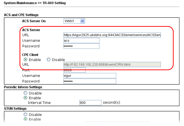
Next, on the remote device in the System Maintenance >> TR-069 submenu, you need to enable it to be managed by entering the settings listed above:
And check the Allow management from the Internet field in the System Maintenance >> Management Setup submenu.
Next, you need to restart the remote router and log in again to the Draytek 2925 web interface.
If the configuration is done correctly, in the Central VPN Management >> CPE Management submenu you will see the device you just added.
Fig. 43-3
Now the remote router, in our example, this is Vigor2860n +, can be configured from the Draytek 2925 web interface. In addition to setting up and monitoring VPN tunnels, you can update the software version, save and restore the configuration, reboot the remote router. This can be done for one device or for a group of devices. Detailed instructions, including in the format of "how to" is in the user manual.
In the CVM >> VPN Management submenu, you can configure and monitor VPN tunnels.
To do this, you need to click on the remote router you want to configure, and select the type of VPN tunnel. When you click on the type of tunnel, for example, IPSec, it will be created and activated automatically.
Fig. 43-4
When you click on the Refresh link, you will see the status of the created VPN connection.
Fig. 43-5
This will create a LAN to LAN profile automatically. If necessary, profiles can be adjusted manually, the only restriction is that you cannot change the name of the VPN profile, as this may cause an error in the operation of the Central VPN Management tool.
Central AP Management menu
This menu is used to automatically detect, configure and service Draytek access points.
In the Central AP Management >> Dashboard submenu, the active access points are displayed. Moreover, the Draytek 2925 automatically finds access points to the network and displays them in this submenu.
Fig. 43-6
The Central AP Management >> WLAN Profile submenu contains access point settings profiles.
WLAN profile is assigned to the access point, then the access current is automatically adjusted or reconfigured according to the settings specified in the profile.
Fig. 43-7
To apply a profile to an access point, tick the profile, then click the Apply To Device button and select the desired device.
Below are the detailed profile settings, the setup takes place in four steps: on the four pages all the settings are consistently set. As you can see from the example, there are a lot of settings.
Fig. 43-8
Fig. 43-9
Upon completion of profile editing, on the fourth page, click the Finish button to save all settings made in the profile.
The Central AP Management >> Status submenu displays a list of all access points, their status and detailed settings.
In the Central AP Management >> AP Maintenance submenu, for one access point or group, you can perform the following service functions: saving and restoring configuration, updating firmware, rebooting, resetting to factory settings.
Next, there is a group of submenus for monitoring access points: Traffic Graph - a graphical representation of the total traffic from access points, Rogue AP Detection - detection of "their" and "foreign" access points, Event Log - viewing the event log, Total Traffic - traffic passing through configured LAN segments, Station Number — total number of active wireless clients.
In the Central AP Management >> Load Balance submenu, load balancing is configured by specifying the maximum number of wireless clients on a 2.4GHz and 5GHz network and shaping incoming and outgoing traffic on each wireless client.
The Central AP Management >> Function Support List submenu displays a list of supported functions for the current firmware, depending on the model of the access point. Information on two tabs - for the client and for the server.
Fig. 43-10
Wireless LAN menu
The router, depending on the model, supports 802.11ac, 802.11n, n-plus wireless network and has two or three omnidirectional antennas. The settings of the wireless network functions in the router are large.
The device supports up to 4 independent wireless networks with their own settings, and for each of the networks you can limit the maximum bandwidth for outgoing and incoming traffic, and also enable the schedule according to which these restrictions will work.
Below to illustrate the settings are the General Setup and Security Settings submenus. The settings are very visual.
Fig. 44
For each of the 4x wireless networks, their own security settings are configured, including MAC address filters. For each network, you can enable the Wi-Fi usage quota based on the MAC address and the timeout for re-quota provisioning.
Below is the Station List submenu , which shows the currently connected wireless terminals.
Fig. 45
In addition, in the Access Control submenu, you can enable the MAC address filter, and create both white and black lists of MAC addresses. Lists can be saved to a file on a computer or downloaded from a file, if necessary.
The Advanced Setting submenu contains radio channel fine tuning, for example, outgoing signal power, operating mode, channel width, fragment length, and others.
Wireless also supports configuration via WPS (Wi-Fi Protected Setup) and WDS settings, which can be found in the corresponding sub-items of the Wireless LAN menu.
SSL VPN menu
In the Draytek 2925 router, you can configure application access via SSL VPN using a standard web browser.
This method provides certain advantages over traditional VPNs, including the absence of the need for additional software, for example, a VPN client to create a secure connection, another advantage: fewer restrictions on data encryption using SSL compared to traditional SSL.
The service is globally enabled by installing a checkbox for the option Enable SSL VPN Service in the VPN and Remote Access >> Remote Access Control Setup submenu .
Further, in the SSL VPN >> General Setup submenu, it is indicated on which WAN interfaces the service is available and on which port. The default is 443. I advise you to change it to another, in order to avoid a conflict with the standard port for Draytek web management.
Further, by analogy with the above VPN settings PPTP and PPTP, in the SSL VPN >> Remote Dial-in User submenu, you need to configure users who can use SSL VPN by setting the checkbox for the SSL Tunnel option .
Now in the SSL VPN >> SSL Web Proxy submenu, you must specify the URL addresses for which you need to open access via SSL VPN. In the SSL VPN >> SSL Application menu, you can select the application and host and port, for example, RDP on 192.168.1.50:50389, which will be forwarded via SSL VPN.
After saving all the settings, the user opens a web browser, enters the IP and port on the WAN interface, where the VPN SSL service is running, authenticates with the administrator's login and password, then goes to the page with VPN SSL services available to him.
Fig. 45-1
In the SSL VPN >> Online Status submenu, active connections will be displayed.
Fig. 45-2
USB Application Menu
The router has a USB port that can be used in three different modes. First, connect a USB 3G / 4G modem to reserve an Internet connection or as a basic Internet connection if there are no other ways to connect to the Internet.
Secondly, connect the USB printer to the router, which becomes the print server and users will be able to use it by setting up access to it over the network.
Fig. 46 , , USB- FTP SMB. .
, USB Device Status, , USB- 8 , .
. 47
-, USB- FTP NetBios/SMB. Modem Support List, LAN SMB Client Support List.
3G/4G , Modem Printer USB Device Status .
. 47-1
System Maintenance
. User Administrator, TR-069 . Configuration Backup . Configuration Backup SysLog, . , .
. 48
, Draytek syslog . Draytek Syslog. .
. 49
Management . , , WAN .
. 50
Diagnostics
, — .
Routing Table , ARP Cache Table MAC- , DHCP-Table DHCP-, NAT- DNS-.
. 51
Ping Traceroute . , : VPN, Firewall, WAN .
. 52
Traffic Graph , , WAN .
. 53
findings
Draytek 2925 2925n , . , , , , Draytek 2925n, , , , VPN-, NAS- . Drayatek 2925 – , 6 , VoIP.
, , , – . Draytek VigorACS SI, , . Draytek Smart Monitor, , . 2925 Central VPN Management VPN- Draytek 2925 . VPN- .
, Dryatek 2925 AP Central Management, - , .
High Availability, 2925 «» Draytek, , WAN .
, , . .
, , , WAN LAN, , , VPN, , NAT , USB, . SSL VPN, High Availability, VPN- Central AP Management Central VPN Management. , , , Draytek .
Draytek 2925n , , -, CLI TR-69. , VigorACS SI Smart Monitor , . «», SMB+ , «» 100\ WAN- -. , . , , , .
Source: https://habr.com/ru/post/397537/
All Articles