Robotics - making a basic platform for the future of the robot
All cheerful / good (underline the necessary) time of day and good mood! I want to tell and show the process, as I invented (designed) and produced a base chassis for a four-wheel robot.
Familiar guys again turned to me with a request to help make the robot "more serious." This time it was decided not to make a full-fledged robot, but some kind of basic platform that would allow to design further robot functionality on it, possibly with variations, without being distracted by questions about the chassis, engines, power system and, ideally, local or remote system management.

')
The purpose of this post is to show the process of developing and manufacturing such a platform. Usually, articles on robotics show ready devices, demonstrating what has been done and how it works as a result. This is interesting, of course. But with great pleasure I read articles in which it is shown step by step exactly how it was done, why the description of some particular moments or thoughts. I will try to describe in detail how the moving platform was going at home. This article is a profile reading for recreation. I prepared the article itself, probably, more than three times more time than I was engaged in needlework. I do not pretend to be complete, high-tech, science-intensive, innovative and infallible ... But I hope that for someone it will help to take some first steps and show that modern modular electronics is not at all difficult, although not quite as simple as it seems. . "Uncles again play with cars instead of doing serious work." But you need to do something for those who can not grow. Caution - under the cut there will be a lot of text and indecently a lot of pictures.
I have already done, or rather collected, a RASH1 robot. It is difficult to call this robot handmade, since the platform is absolutely assembled on ready-made components. Of interest is the control system of such a platform, built on the basis of a small router with the cyberWRT system, which allows you to control the robot from any device through a browser. I confess that the meaning of the work was more in demonstrating the development process itself from the point of view of methodology and documentation, rather than in direct production. On this occasion, in Habré, a measure of good faith, an almost conceptual article was written down, since I decided that since I tried to describe the development, I’d do it for everyone, especially the startup initially aimed at open source and the guys were not against such an initiative .
If you watch the video, then make sure that the Chinese motors for 300 rubles are very different and sometimes it is not easy to pick them up the same, especially if there are no others. And, if they turn unequally, the robot will not go straight. Although, by his desire once again to duck to the left, he did not leave a single household indifferent, such an effect is clearly undesirable. You can put the encoders and programmatically adjust the rotation of the wheels. If there are no encoders, then you can empirically calculate how much you need to slow down (lower the voltage level) a faster engine so that the robot drives straight and level. However, as the batteries / accumulators discharge, the characteristics of the fitted “operating point” will change and, at a different voltage, the motors behave quite differently - the robot will again begin to “take” in some direction. In addition, the control of the robot via cyberWRT is still not perfect - the connection was broken, sometimes the picture disappeared, I don’t remember exactly, it seems that the control of touch buttons did not work at all on Firefox. After reconnection to the robot, everything was restored, that is, it was repaired without rebooting the router, perhaps some kind of capriciousness in the computer / telephone-router-router_broken connection took place. It is worth noting that cyberWRT quite simply solves the issue of management organization, giving the opportunity to write your module and convert, roughly speaking, WEB on the one hand to the UART on the other. There is enough Russian-language information on the Internet, and there is also a fairly active community that can help sort out some issues. Well, the robot turned out more for demonstration and study, than for purely practical use. He was very fun and smartly traveled without the second floor, but he became noticeably sad when a router with a small USB hub and a video camera was added.
By itself, the assembly of the robot RASH1 completely allows beginners in robotics to take the first steps without focusing on the development of electronics, putting a minimum of effort with a soldering iron in their hands (there is a ready-made diluted board, which is easily untied) a self-made robot - I am sure that a normal robot engineer will not grow up on lightweight electronic designers alone. In principle, this is already enough: the resulting robot, and without control via cyberWRT, allows you to program your behavior. It is enough to understand Arduino ( circuit design and programming ), to master the concept of pulse-width modulation ( Ref. 1 , Ref. 2 ) and search the Internet for examples of the application of certain sensors.
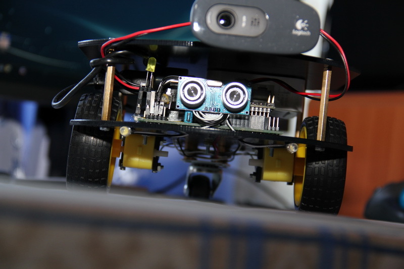
For example, the basic firmware has an autonomous mode, which is activated by pressing a button on the robot and allows the robot to travel indoors, ideally without colliding with objects - a sonar (ultrasonic sensor) constantly monitors the situation in front of the robot and when it detects an obstacle, the robot stops and starts slightly heaped the reversal algorithm, the essence of which is to get random turns in order to triumphantly leave any trap out of the furniture cleverly arranged by people. You can add another sonar, improving the "vision" of the robot. You can connect the light sensor and, by its values, turn the “lights” of the robot on or off so that it is “more visible” in all dark corners under the tables and chairs. Or connect a motion sensor, for example, an inexpensive HC-SR501 (based on the BISS0001 chip) to teach the robot to hide from people. In general, there is a lot of scope for creativity, entertainment and knowledge of how electronics work at a “low” level.
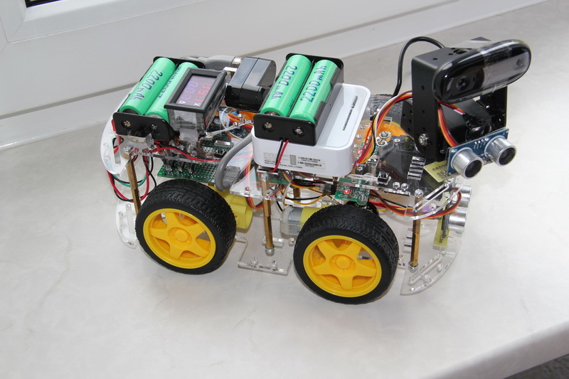
After RASH1 I became interested and I made a RASH2 robot. This robot can already be classified as handmade. The purchase platform was taken as the base - the upper and lower glass-fiber laminate base, racks, motors are all a single set purchased in the “Great Chinese Internet”.
This robot has already developed its own electronics, which is made on a breadboard, to which connectors were soldered, and the role of tracks was performed by wiring. Power is supplied, not from AA batteries / rechargeable batteries, but from four lithium-ion batteries of size 18650. Servomotors are installed that allow the “head” of the robot to rotate in two planes. On the "head" of the robot is installed a video camera and sonar. In the automatic mode, the robot no longer needs to spin entirely - just “look around” with a sonar. The robot has the same "yellow" engines, like the previous one, and was originally conceived as a front-wheel drive, but then had to be redone to all-wheel drive because of absolutely no dynamics due to a decent weight. Encoders are already installed, but there is no special meaning in them, since the robot is quite heavy and the neighboring wheels on one side will slow down each other on their own. The control system is also built on the TL-MR3020 router with cyberWRT firmware.
Designing such a robot is perfect for those who want to gain experience of initial development and move on - self-developed electronics, complete soldering in its concept, design and own assembly, understanding of servo control ( article from Amperca ). On the Internet, you can find a similar, almost ready whale, which includes the necessary components - I did it and assembled it from sticks and ... in general, from what was at hand, periodically drilling through, undermining, sticking, screwing, even scotch taped - where do without him.
And now, now the new robot. What do we want from him?
We want the platform to be strong, load-carrying, with good maneuverability and ground clearance (clearance). We want to get a universal platform so as not to make a new one every time - the practice of life, however, usually proves otherwise - but as many developments begin, this is a normal and healthy desire. What is the image of a universal platform based on the requirements outlined above? Probably, this is a metal chassis, four engines with good power and big wheels. Obviously, it is better to close the engines in a separate closed compartment. In this engine compartment it would be nice to remove the driver for the engines, batteries, and some kind of power electronics. For example, the same DC / DC voltage converters, if present. I don’t want to change the batteries, just as I don’t want to pull out the batteries for recharging - everything is inside the platform and let it be able to recharge the batteries. For additional equipment, it will be possible to install metal racks and organize a “second floor” on the platform.
First of all, I divided the process of creating a full-fledged robot into two parts - the creation of some kind of universal platform and the creation of a robot based on this universal platform. This allows you not to think about the robot as a whole, thinking only about the junction of these two parts. Further we will talk only about the platform.
The second important point is the division of the platform itself into two parts. The first part has already been described - engines and power. But the engines need to be controlled. The control device will obviously be based on some kind of microcontroller - will it be put inside the engine compartment or not? The temptation is to make a completely ready-made stand-alone platform. But rationality suggests that the microcontroller is purely for controlling engines, plus some kind of interface for receiving commands - this is a wasteful computational expense. Therefore, it is better to isolate this part of the motor-power compartment.
As a result of thinking, the idea itself is made as follows. There is a closed platform, inside which are located the engines, the driver for the engines and the power source with the necessary power electronics. Obviously, it is better to have some kind of central switching card to which all these components will be connected. Also, this board will have the necessary electronics to obtain the necessary voltages. Let's call this board the power board. On the platform there is a board with a microcontroller, which is connected to the power board, receiving power from it and issuing commands for the engines to it. The microcontroller board can also control other robot equipment. This card will be called the control card.
Thus, the development process of the entire robot is conditionally “sawed” into two (three) parts: creating a platform (and its controls) and drawing an owl to create the rest of the body kit, which turns our platform into a full-fledged robot. The important point: while working on each stage, you can not think too much about others - think well enough of the “joints” between these parts.
After all these thoughts, the selection of components for the platform began.
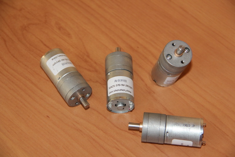
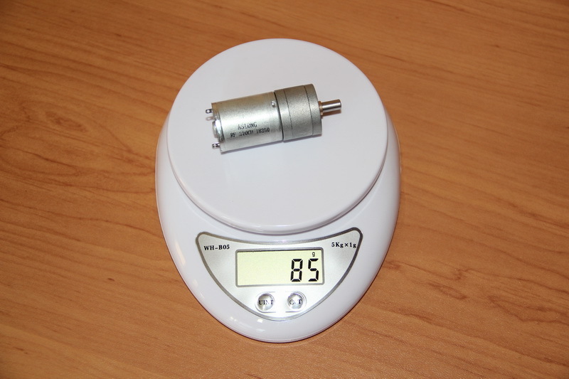
After studying the proposals, I chose the engines of the JGA25-370 family.
Judging by the description of this series of engines, they have an operating voltage range of 3-36 V, nominal voltages of 6-24 V. These engines are available at different speeds, gearboxes and, accordingly, have different torques (0.1-10 kg * cm ). The size and attachment points of the entire series are the same, so we get a good universal solution in terms of future modifications - for a heavier and more heavy-duty platform, for example, you can install engines with lower speed, but greater torque. Typed operating voltage ratings for 6, 12 and 24 V motors. An important question is which nominal to choose?
In connection with the choice of engine power raises the question of the organization of autonomous power for our entire platform. I did not want to use batteries and rechargeable batteries of size AA or AAA. I wanted to use really capacious batteries. I chose lithium-ion batteries of size 18650, the capacity of which varies from 1000 mAh to 3500 mAh. I already have a positive experience with them, a good device for charging, and the batteries themselves are actively used in everyday life, that is, for me this is not a novelty.
Lithium-ion batteries have a sufficiently large number of charge / discharge cycles, a fast charge time with a relatively high current, no memory effect (although according to some sources, it is, although small, but there is), a low level of self-discharge, less weight than acidic or alkaline batteries, more capacity than NiMH batteries. However, it must be remembered that such batteries do not like excessive heat (probability of explosion) or excessive cooling (reduced capacity). They can not be deeply discharged, very quickly charged or discharged very quickly (we will not consider high-current batteries). If the battery is highly discharged, it will surely fail with the likelihood of depressurization while attempting to charge. If the tightness of the battery is impaired, then with strong currents there is a probability of lithium ignition, and it is no longer possible to put out such a battery with water - lithium reacts with water to form alkali and hydrogen. Why all these fears? In addition, the need to understand: the use of such batteries is a serious matter (we remember about the periodic experience from Samsung ).
The rated voltage of a single 18650 lithium-ion cell is 3.6–3.7 V. A fully charged cell produces 4.1–4.2 V. But with a minimum voltage it is more difficult — the final discharge voltage depends on the type of battery and this figure may fluctuate within 2.6-3.2 V. It is possible to discharge even lower, but this is a sure way to the rapid degradation of the battery. I decided to degrade the estimate of the voltage generated by the battery in the nominal-maximum range. Then it turns out that assemblies from two, three and four consecutive batteries give us ranges of 7.2-8.4 V, 10.8-12.6 V, 14.4-16.8 V. From this assembly we need to get two voltage - some kind of voltage to power the motors and 5 V to power the electronics. By assembling two batteries, it is possible to power the motors at 6 V, using a step-down DC / DC converter, but the difference between the minimum voltage value (when the battery is discharged to the nominal, it will be 7.2 V) and 6 V will be about 1.2 V, which can to be insufficient for stable operation of a DC / DC down converter - to avoid problems, you must have a voltage difference between its input and output of at least 2 V (in fact, it may be less for low dropout converters, but we will not be guided by them). An assembly of three elements is quite suitable for us; we obtain the required voltages by applying DC / DC downconverters. The engines can be powered to 9 V, then in the worst case we will get a difference of 1.8 V, which should be quite enough. The assembly of four elements is also suitable, but you need to understand that an additional battery is an extra weight and space, although a large energy intensity of the entire battery.
The second way to organize power is to use parallel connections of the same batteries and step-up DC / DC converter. Then from 3.6-4.2 V the voltage can be increased to 5 V for electronics and up to 6-9 V for motors. It seems that the capacity of such a battery assembly can be easily varied by adding new elements, but you should not forget that the batteries used must have similar capacity and internal resistance.
To charge / discharge serial or parallel batteries, there are special controller boards. Protection controllers protect the battery assembly from over-charging or discharging (voltage control), short-circuit, exceeding the permissible discharge current. When using such simple boards, an external power supply with a limited charging current is required. Charge / discharge controllers independently are able to charge batteries using the cc / cv method with charging current limitation. Advanced controllers for the serial connection of batteries can also provide individual charge for each battery - they balance batteries.
I chose the serial connection of batteries using a protection card and an external charger. In the future, such a simple control board can be replaced with a charge controller with balancing. Although, with parallel connection, balancing is not required, it is necessary to take into account that with strong wear of any single battery, the controller cannot detect this and this can be fraught with something. It should also take into account the fact that the modes of each battery will be different. For example, when removing the same power, batteries with a parallel connection will have to give a greater current than with a parallel connection.
Therefore, engines with a nominal voltage of 6 V and an operating range of 3-9 V are suitable. I chose a motor with a speed of 281 rpm and consumption, in idle mode, 80 mA. Under load, the speed sags up to 238 rpm, the current rises to 380 mA, while the engine produces a power of 2 W and develops a torque of 0.5 kg * cm. When the engine is stopped, the torque increases to 4 kg * cm, and the current reaches 900 mA. All these characteristics were taken from a tablet posted on the website of one of the sellers of goods, since I could not find a normal datasheet.
I ordered the following engines.
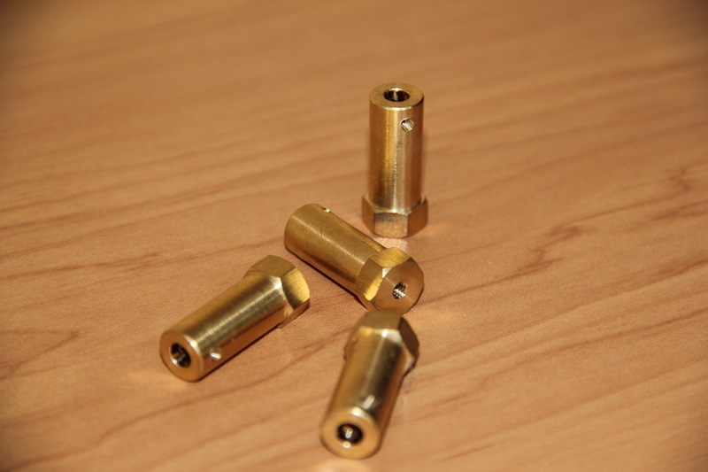
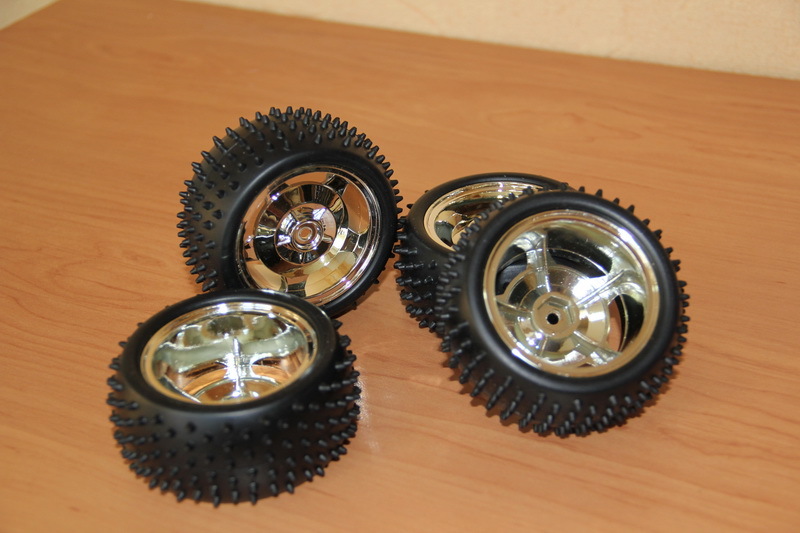
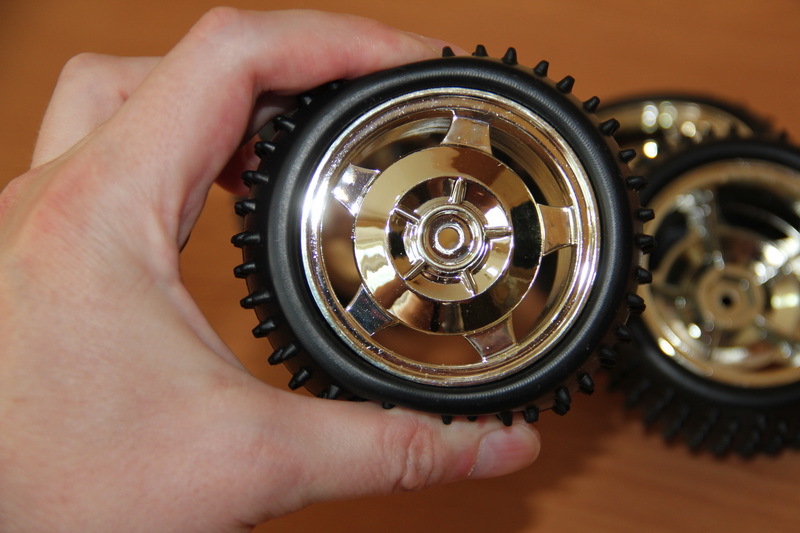
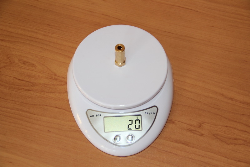
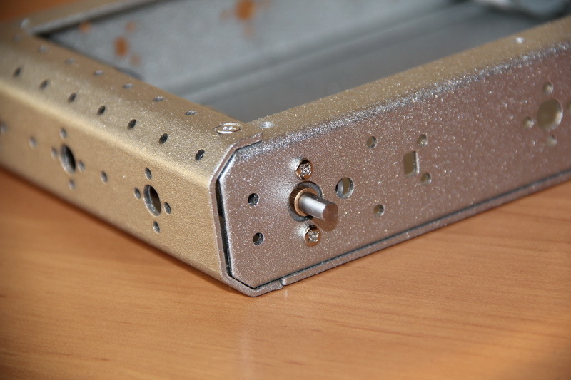
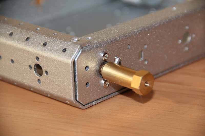
If you look at the photo, you can see the slots on the shafts protruding from the engines. For these engines was found a set of couplings and wheels.
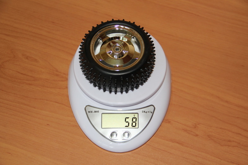
Wheels with a diameter of 80 mm, rubber soft, studded.
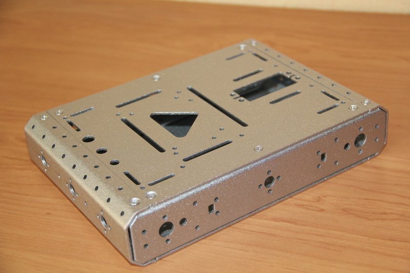
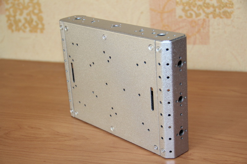
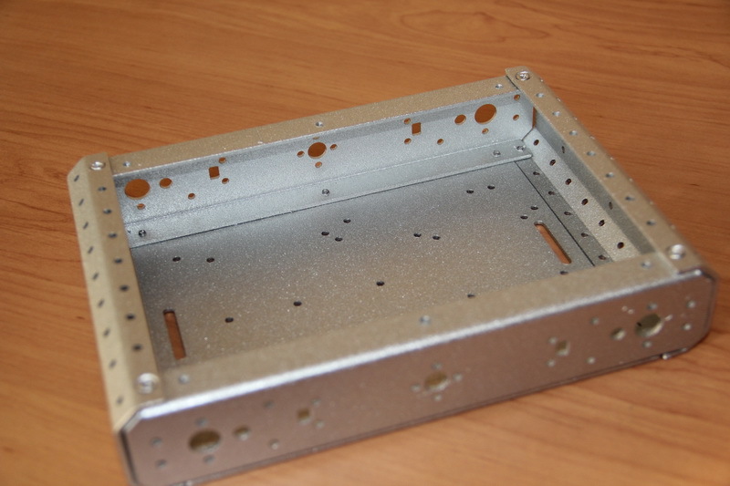
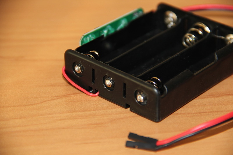
The very basis I was going to make from wide aluminum corners (or something similar that can be found in hardware stores) with the help of which to make a “side” frame, which can be closed with some kind of light, strong metal plates. Holes are drilled in the right places and threads are cut as needed. However, at first I decided to look for what the Chinese industry has to offer. And I found a whale - a chassis kit for designing a robot that contained the body itself, the aforementioned engines, couplings and wheels, as well as the battery compartment for AA batteries, the power switch, the power socket and fasteners. The case itself has many holes, which logically makes it easier and their presence should minimize the amount of plumbing work.
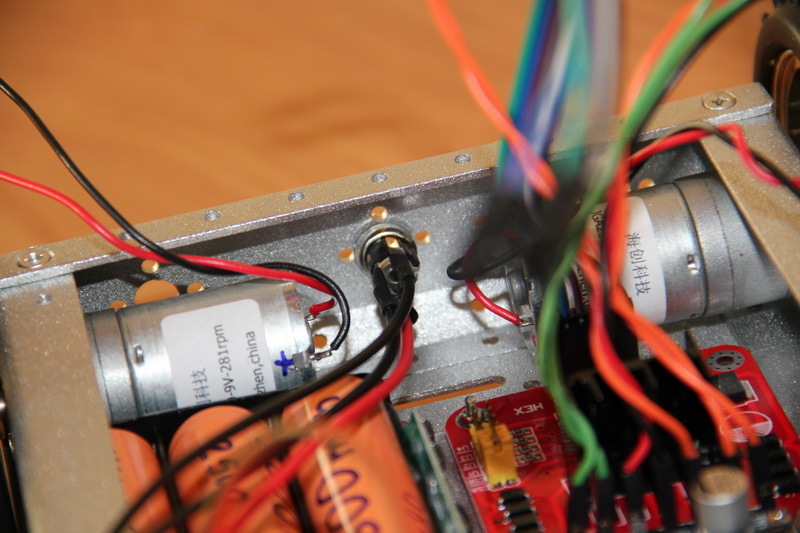
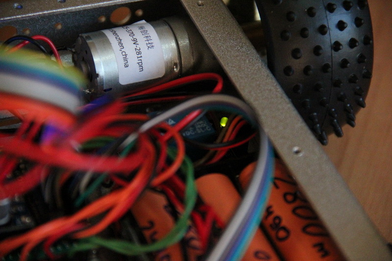
Having estimated the size and volume of the internal space (in parallel, electronics was chosen for the platform, which should fit in this building), I ordered this kit. On incoming engines, as can be seen above, for some reason it is written JGA25-370-9v-281rpm. Why exactly 9v, when the nominal value of this subgroup is 6 V, I did not understand, but, probably, the Chinese know better what to write in order to sell better.
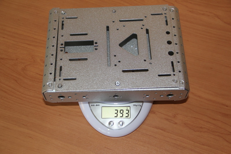
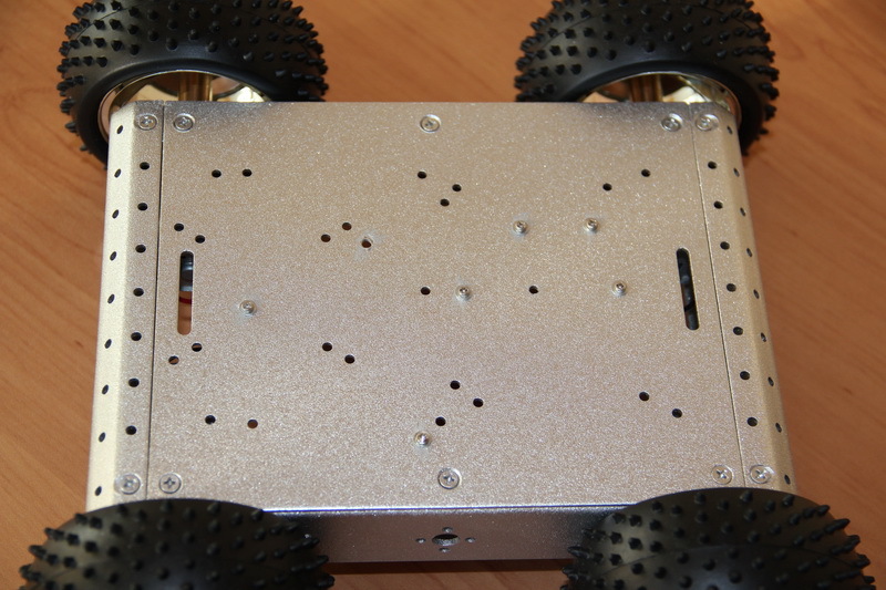
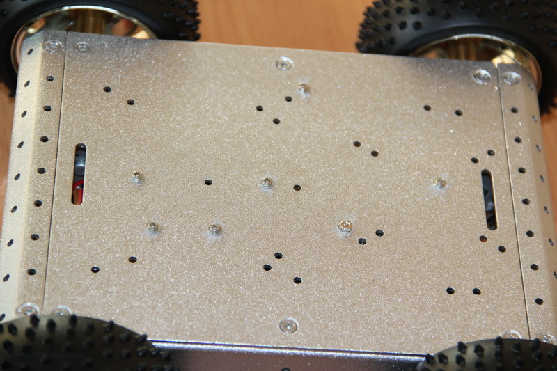
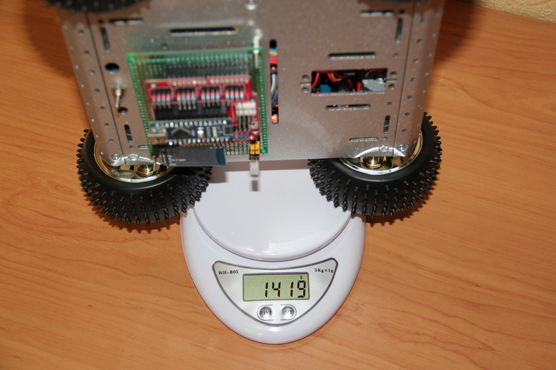
The case itself weighs almost 400 grams. What material it is made of, I find it difficult to answer, but it is unlike the pure aluminum.
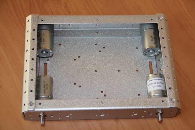
Remove the cover and install the engines. The holes for the engines have a diameter just for the M3 screws, no reserve is left for the adjustment of the position, but, we must pay tribute, it did not cause any problems - the holes clearly coincide with the threads on the engine housing.
We install couplings.
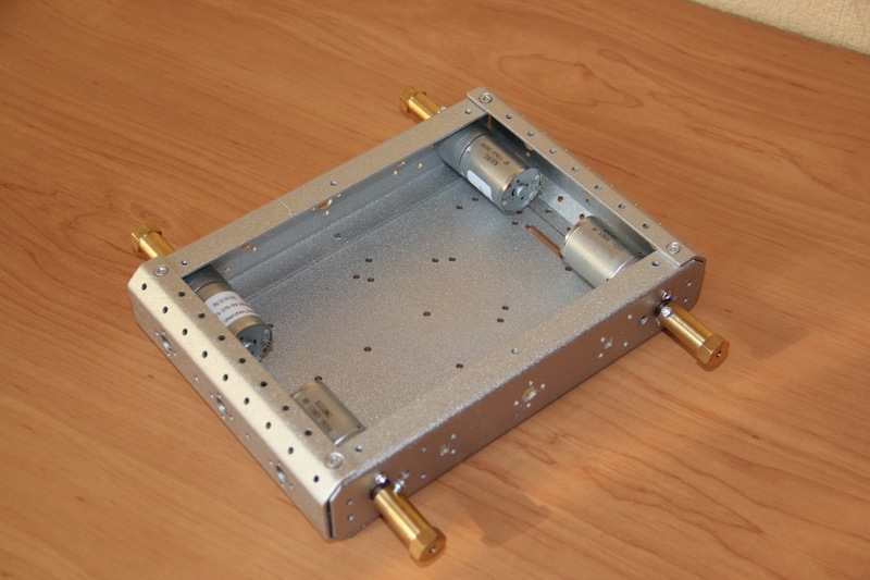
And fasten the wheels.
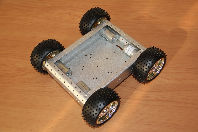
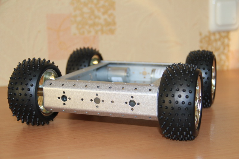
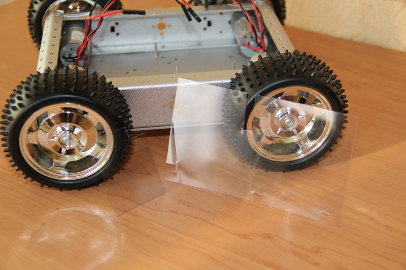
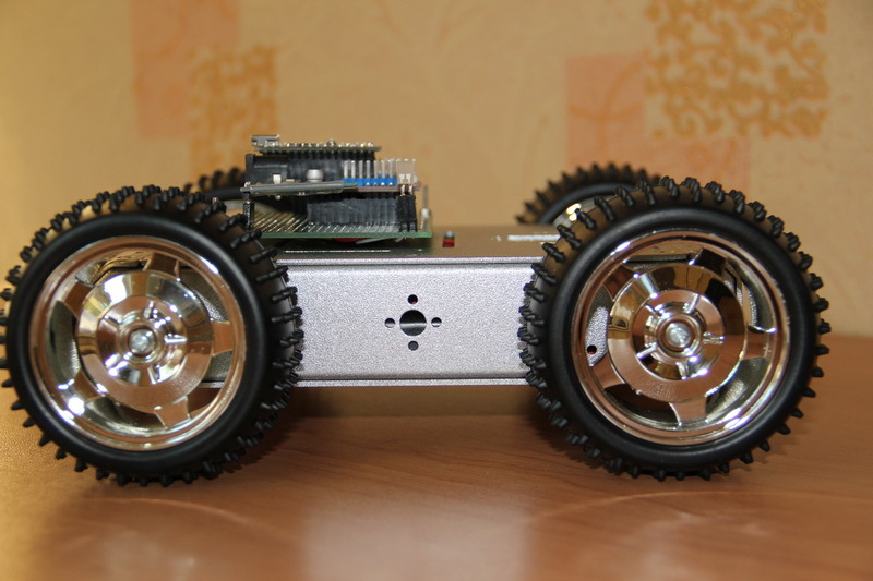
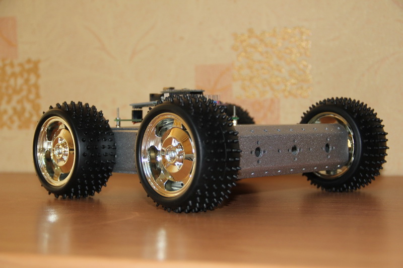
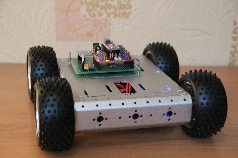
The result was a finished platform with a ground clearance of about 23 mm.

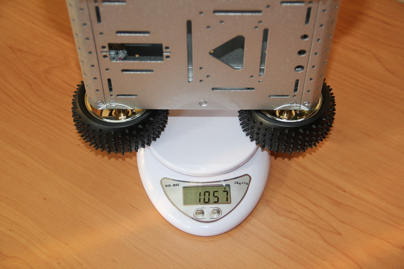
The weight of the “idle” chassis was a little more than a kilogram. Remember the pictures with the measurement of the mass of individual parts? 393+ (58 + 85 + 20) * 4 = 1045 grams. Everything in the collection weighs 1057 grams. 12 grams added 16 bolts.
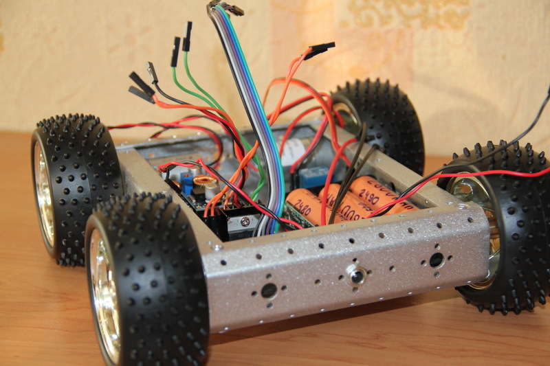
That turned out to be quite a pretty platform.

Here it is worth explaining an important point why this particular whale. The fact is that if we manufacture the case ourselves, then its internal volume can be made arbitrary. The purchased case provides us with a strictly fixed volume in which everything should fit. Ideally, more and stock to stay. This must be taken into account initially and be understood: whether the desired filling will fit in this body or not, and it will be necessary to either change the electronics or choose another body. Inside the case there will be installed: motors, battery, driver for motors, power board, on which some electronics will also be located - the same voltage converters.
It seems to be clear what exactly we will have inside. But how will it all connect? If you have an idea, but you can not create her image - you have no idea. In electronics, it turns out that there must be two images - a visual one, which we can already fully imagine, and an electrical one (in fact, there is also an algorithmic one - when the device behavior is signaled due to its hardware and / or software (firmware functionality) capabilities).
I spend a lot of time on the way to work. Generally speaking, with the right approach, a long way can be turned into a plus, reading books, watching / listening to popular science programs or audiobooks that you would never read, listen to or watch. Thanks to such conditions, I became a fan and listened to all the stories of the Model for assembly (so that there were no questions in the comments - an article on Wikipedia ). Robot-buoy was no exception and I thought out the schematic diagram of the platform and drew it on the road on the tablet .
The scheme is drawn in OneNote. The picture is clickable. Yes, I am ashamed - the concept does not look fundamental. For the last three weeks, I can’t take the time to fine-tune the article and the question has already arisen whether to publish anything at all or to postpone it for later. Decided to publish so, otherwise "for later" may be fraught. I will draw normal schemes - I will replace the pictures. On the other hand, this design looks in the style of the original DIY. At work or at home, when an idea is formed, at first an ordinary sheet of paper and a regular pencil are taken ...
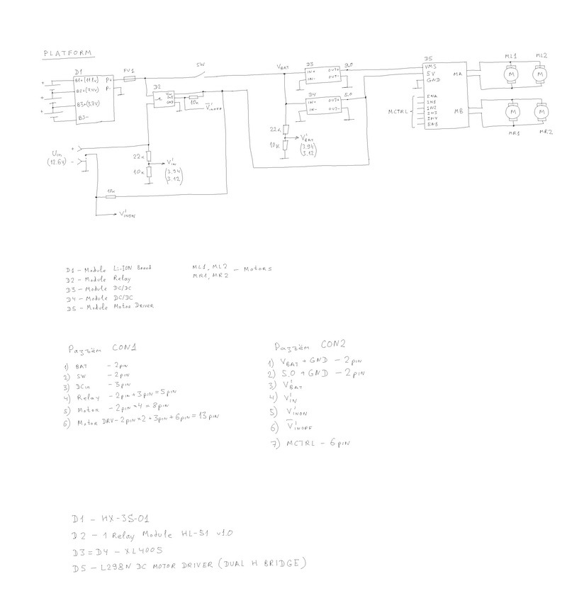
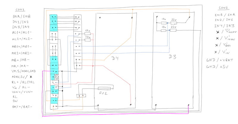
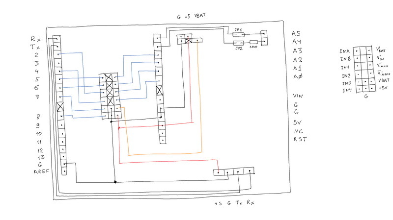
Let's look at the concept of what we will have to connect with. Three 18650 batteries are connected to the D1 lithium-ion battery controller. The entire common ground circuit is connected to the output of the P-controller D1. The P + output, through fuse FU1 and switch SW, is connected to the DC / DC inputs of the D3 and D4 converters. Converter D3 generates a voltage for the motors, D4 - to power the entire electronics. The outputs of these converters are connected to the driver of the D5 engines to which the motors are connected. To the channel MA are connected the engines ML1, ML2 of the left side, and the MB - MR1, MR2 of the right side. Two-channel driver, this means that it will be possible to control two groups of engines (channels A and B), but not individually each engine. The ports ENA, ENB, IN1-IN4 are used to control the speed and direction of rotation of the motors. The resistive chain that forms the voltage Vbat 'is chosen so as to form in the range 0 ... 5 V the telemetry of the voltage Vbat of the battery pack. If Vbat = 13 V (which should not be, since the battery pack can produce a maximum of 12.6V, but I was a little reinsured), then Vbat '= 3.94 V (that is, the value is guaranteed not to go beyond 5 V). The current flowing through the resistive chain at 12 V will be equal to 3.6 mA, and I considered these losses acceptable (about 0.1% with a battery capacity of 3000 mAh). A socket for external power supply is connected to the input of the D1 controller. But, we see according to the scheme that it is connected through the D2 relay.
First I want to clarify the presence of a 10 kOhm resistor that pulls one of the pins in the power connector to a voltage of 5 V. We have a power connector with three outputs. A pair of outputs transmit the power supply voltage. The third output is informational. It is closed to the negative output (it is connected to the “ground”) if there is no plug in the socket and it opens if the plug is inserted into the socket. Thus, we get the Vinon 'telemetry signal about connecting the power supply: if the voltage Vinon' = 0, then the external power is not connected, if Vinon '= 5 V is connected. A 10 kΩ resistor pulls the output to 5 V. When the plug is connected, a current of 0.5 mA will flow through the resistor, which is quite acceptable.
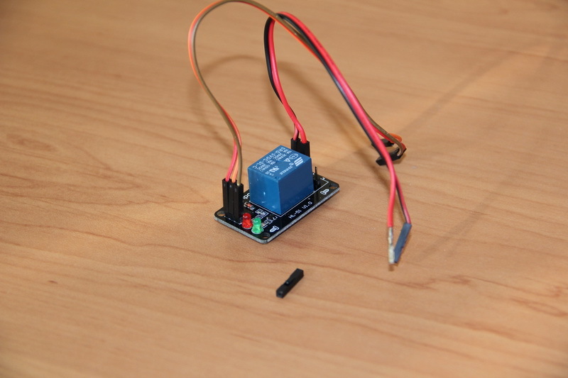
When an external source is connected through a normally-closed relay D2 and fuse FU1, the batteries will begin charging. A normally closed relay - this means - its outputs are always closed and open only when voltage is applied to the control contact. Why relay D2? Suppose we do not have this relay. If the power supply unit is connected to the platform, but you forget to plug it in - how does the microcontroller board know if the battery pack is charging now or not? And if the power source is plugged in, but does not give a voltage? Or does it work, but the power supply produces only 10V instead of the prescribed 12V? And, if I connected such a source (which only gives 10 V) to the battery, which is not yet discharged to the end and gives 11 V, then how do I know that the 11 V is formed by the battery pack (which actually does not produce above 10V) or external source? For such situations, the algorithm was considered, for which a relay was required. About connecting an external power supply, we learn from Vinon 'telemetry. Turning off the relay and look at Vin 'telemetry. If it suits and this voltage is in the expected range, then turn on the relay and signal the process of charging. If not satisfied - do not turn on the relay and signal the malfunction. Let the onboard control board, not the platform, deal with the process of analysis and indication. To do this, we will give it all the necessary voltages and a control signal for the Vinoff relay. The control input of the relay module through a 10 kΩ resistor is pulled up to 5 V, ensuring the relay is constantly turned on. When 0 V is applied to this input, the relay will turn off.
But why, precisely, the antediluvian mechanical relay? After all, you can put a MOSFET transistor. Such an idea was, but it had to be abandoned. Modern MIS transistors have low resistance (tens of millimeters) in the open state and with a current of 2-5 A there will not be a very significant voltage drop and, as a result, heating - a small power can dissipate the transistor case itself even without a radiator. But all this concerns the scheme in which such a digital key will control the connection of the power source to the passive load. We put a transistor between two sources, as a result of which the voltage difference between the drain and the source can be significant, which will lead to increased heat generation and the transistor will be very hot. Also, for opening or locking the transistor, it will be necessary to make a control circuit (driver), because the control voltage level from the microcontroller board is 5 V, which is not enough to create a gate-source voltage difference to control the transistor (for controlling the transistor, for example, IRFZ44N we will have apply on his shutter 8-12 V in order to open it). Whether business - the ready module of the relay which needs to be simply connected and which if it is closed, then with guarantee connects an exit to an entrance without any troubles.
Thus, we have turned out not just a switching board, but a full-fledged power board. On the board, DC / DC converters, resistive circuits, a fuse and a bunch of connectors for connecting electronics are installed. Structurally, there are two connectors. The CON1 connector to which the battery pack will be connected, the power switch / button, the power connector, the relay module, the motors, the motor driver board are all peripherals inside the platform. And the CON2 connector, the purpose of which is the connection to the control board. The telemetry and control signals, voltages of 5 V are output to this connector, and it is also useful to “push” the voltage from the Vbat battery pack — we enable the “higher level” to organize our power channels with different voltages, for example, 6 V to power the servo drives.
Electronics was chosen in parallel with the development of the electrical circuit of the device.
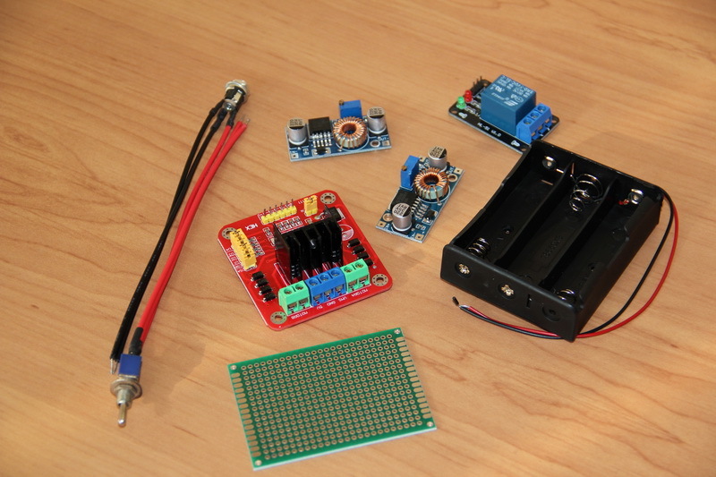
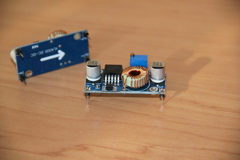
The power socket with the tumbler went into the business from the received chassis kit. A driver for L298N chip-based motors, XL4005 DC / DC converters, an unnamed relay module, a battery compartment, and a circuit board with dimensions of 50x70 mm and pitch of 2.54 mm were selected and purchased.
In addition, we still need the following materials.

At the top of the photo you can see several long pin connectors with a pitch of 2.54 mm, as well as sockets, below are metal contacts on the cable, to the left are sockets for them, to the right are screws, nuts and M2 washers. Connectors on the board and the cable in different stores are called differently. For historical reasons, I call the pin connectors for the PLS board, the jacks on the board are PBS, and the cable connectors are BLS. On the Internet on foreign sites, such connectors are searched on request of the "2.54mm connector" or "dupont connector" type. In addition, you will need a variety of consumables - solder, flux, wires, and so on, as well as a set of hand tools - nippers, tweezers, screwdrivers, etc. - usually those who do DIY at least ( Do It Yourself do it yourself).
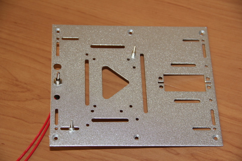
Before ordering the electronics and the case, I figured that the selected electronics should fit in the internal space without any problems. The time has come to check it out: we arrange the electronics and mark future seats.

Now we are going to prepare the boards.
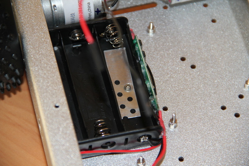
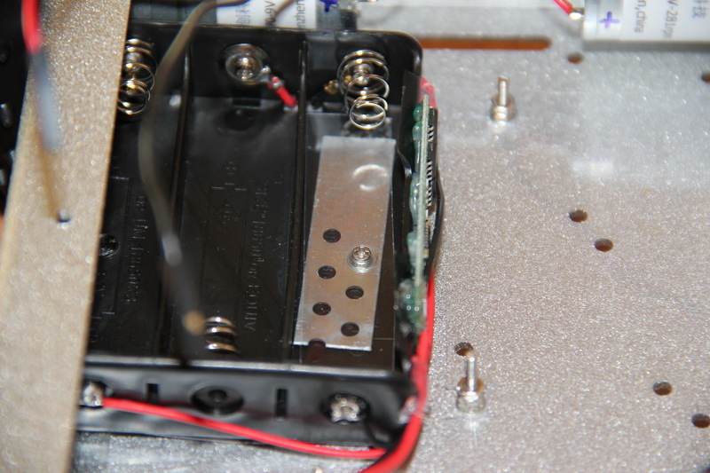
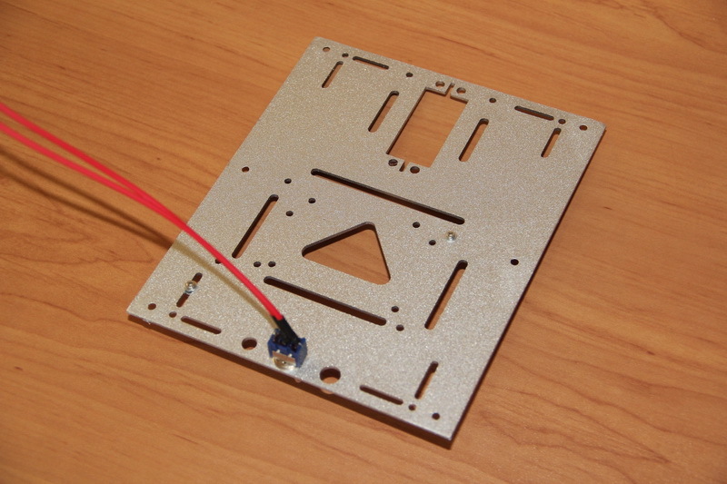
I started with the battery pack. The controller of lithium-ion batteries was “planted” on hot melt glue and the terminals of the contacts were soldered to it in accordance with the circuit diagram. I think readers will be interested in what and what tool was done, so at the end of the article, under the spoiler, I posted pictures of some used equipment with my brief comments. Hotmelt adhesive was applied with a thermogun. However, before that I had to work on, so to say, increase the reliability of this compartment. I will warn everyone who is going to do something - it is better not to make my mistake and take more durable battery compartments. At one time I could not find such compartments at retail, and when I did, I scored a lot of them for the joy of spiritual simplicity. And with them everything is not so simple. Because in this compartment, batteries with flat, non-protruding plus platforms simply do not reach the contact. In addition, all spring-loaded contacts rotate, the contact is bad. So I had to screw in the M2 bolts, bite off the excess, tighten the nuts and tighten to improve the contact. But this seemed to me a little, and I also carefully soldered all the connections. Because if something is done, then it must be reliable, so that it does not cause problems in the future and then do not come back to it again.
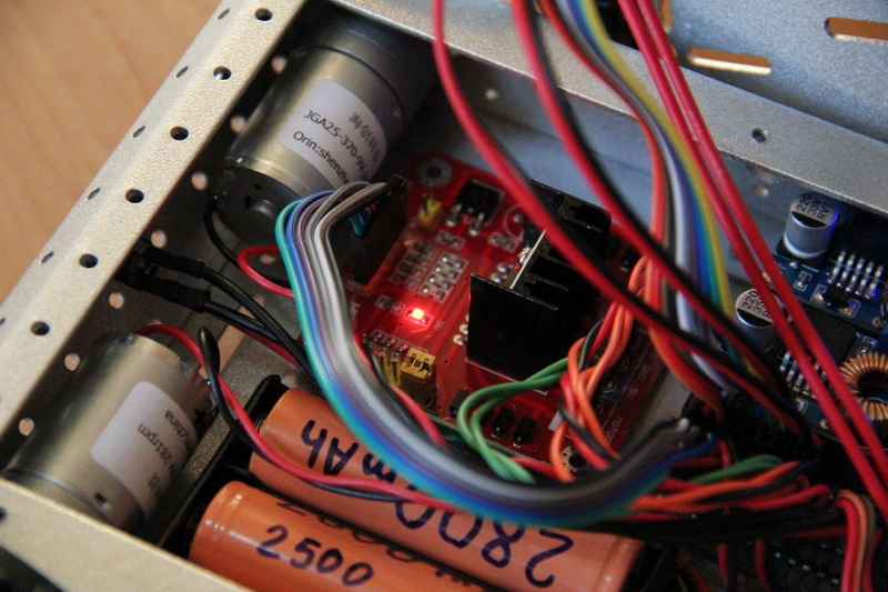
It should be noted that for lithium-ion batteries using a regular controller without balancing. This means that when charging one of the three batteries, the controller will certainly interrupt the charge of all batteries. In fact, it’s just a low-discharge protection board and rechargeable batteries and control of the discharge current. Therefore, it is desirable to use batteries with the same real capacity. If you use a controller with balancing, then the selection for capacity is less critical and the batteries will be used more efficiently, but such controllers are more expensive and take up more space. How to choose batteries with the same real capacity? After all, having bought the same batteries from the same series even from brands, the capacity can vary by 5-10%, and Chinese batteries with inscriptions 6000-8000 mAh, in general, are batteries with an unknown capacity. I used the OPUS BT-C3100 charger, which is quite popular in my environment, to measure real capacities. With the help of it, 12 purchased batteries were checked and three were selected, the capacity spread of which is minimal and does not exceed a few percent. The capacity of LG LGABC21865 batteries was declared at 2800 mAh, but in reality it ranged from 2400-2500 mAh (tested at 700 mA).
A small digression in the form of thinking. The charger considered us the capacity of the batteries, taking into account their charge up to 4.2 V and discharge, if I am not mistaken for the OPUS BT-C3100, up to 2.8 V. In our case, the batteries should not be less than the nominal 3.5-3, 7 V. That is, our battery capacity is much lower than the measured one. This must be taken into account. Perhaps in the future, it is worth thinking about a battery pack of four batteries. Is it possible to simply replace the battery pack and power supply to charge it? Let's estimate. We will have a voltage range of 14.4-16.8 V. The voltage transducers operate with an input voltage of up to 32 V. Resistive dividers will give us a voltage range of telemetry signals of 4.3-5.1 V, which is slightly above the upper range 0-5 Q. But it can be parried at the level of the control board - if the telemetry voltage is 5 V, then the battery pack will be almost charged after a while. On the other hand, if you reduce the voltage on the motors to 6-7 V, you can discharge the existing battery pack more effectively and use the batteries more efficiently - in this case, you only need to adjust one voltage converter. At first glance, there is room for future research without changing the hardware at all, and how to interpret telemetry signals depending on the installed battery pack - let it be solved at the level of the control board, that is, you can not think about it yet.
I cleaned the output wires from the resulting battery pack with special tongs (stripper) and pressed them into metal contacts using crimping pliers (crimper), for reliability I lost and put plastic cases on them, getting BLS connectors. When soldering, a soldering station was used, POS-61 without rosin was used as a solder, and FluxPlus NC-D500 was used as a flux.
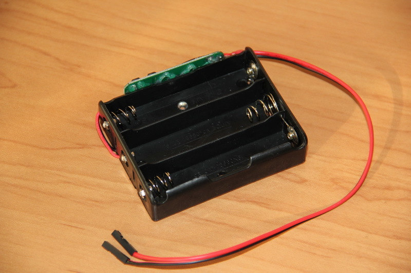
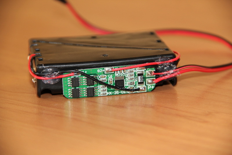
After assembling the battery pack and installing batteries into it, it will not issue anything. Many controllers of lithium-ion batteries are arranged this way - they de-energize the load during a short-circuit, a strong discharge, and an excess of discharge current. In order to “reset” the protection and bring the battery pack into operation, it must be fed 12-12.6 V to the + P / -P contacts. The same should be done after the first connection of the batteries to the controller. After that, you can make sure that the unit provides voltage if the batteries are properly connected to the controller.
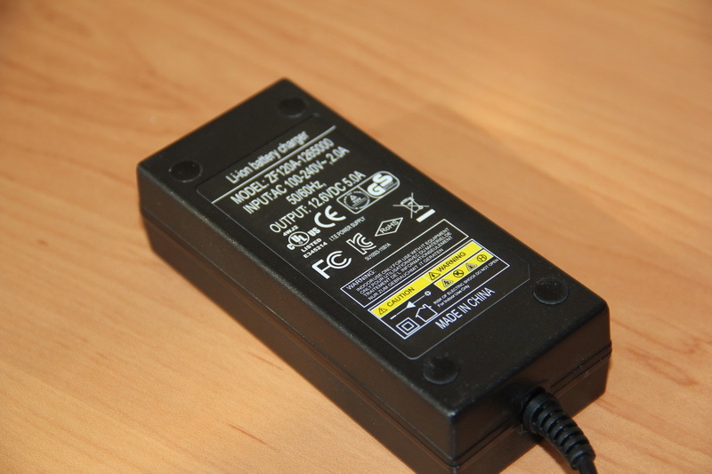
To charge such battery assemblies, there are power supplies with an output voltage of 12.6 V (3x4.2 V). With such a power supply, the batteries will be used more efficiently, although you can also use power supplies with a nominal value of 12 V. I already have such a power supply with an output of 12.6 V and a current of 5 A. If a similar source is purchased, then you should make sure that He claimed characteristics. The simplest test is to test load capacity. For this, I used ceramic resistors of 1 Ohm 10 W and 4.7 Ohm 10 Watts. Having assembled a 2.5-ohm assembly of such resistors, I connected a power supply to it and measured the voltage at its output. With a rated current of 12.6 / 2.5 = 5, my power supply produced 12.6 V, which is an excellent result. Chinese power supplies, on which something is written, such as - 12V3A, often begin to "sink" by 10-20% with a load of only about 1 A.

By analogy, a switch and a power socket were prepared.
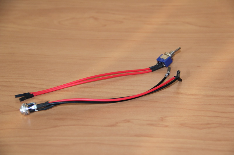
The terminal block was removed from the relay module using a hair dryer and PLS contacts were soldered. To connect this module to the power board, I manufactured the wires — stripped, crimped, and soldered the power wires (through which the power connector and battery pack will connect) with a cross section of 18-20 AWG. And for management I used the wires I had, with thinner conductors, which are easily searched for under the name “Dupont”.

The same was done with the engine driver.
On the DC / DC converters were soldered "legs". It is worth mentioning that these contacts are made of a metal that is well soldered only by the active flux. Then, instead of FluxPlus, I use LTI-120, followed by wiping the soldering spots with a cloth moistened with isopropanol, to remove any remaining flux.
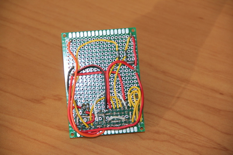
Now we make our board with electronics. For a start, it's nice to imagine in general how and what will be connected on the board. That is, try to draw a circuit board.
[Power Board]
Guess where I came up with and “licked” this board? We see two connectors on the board, two voltage converters. There was an additional jumper (removable jumper), which can be installed by removing the fuse from the electrical circuit - I did this specifically because of the banal absence of a fuse at the time of manufacture of the board.
Wiring a board is quite tedious and painstaking work. For power, I used 18-20 AWG wires, for other signals - 26-30 AWG. Why exactly the breadboard and the trouble with the wiring? Because we still have only the first prototype. Something can change, so rewiring the wiring is easier than cutting the tracks and soldering any jumpers on the finished printed circuit board. It takes time to make a printed circuit board, dilute it, make a mask, etch it, drill it out, tin it, unsolder it is unlikely that this will take less time than making a board with “wiring”. Although the PCB will be more reliable, and look - more professional.
From these considerations, the DC / DC converters modules are not unsoldered on the board, but are made in the form of removable modules, ideally, after the initial debugging, they should be additionally fastened to the connector, for example, by dripping hot melt. Not bad in the same way to increase the reliability of the connection of all connectors. But while we have a prototype, it is more convenient for us to make everything removable so that in the course of future debugging we can have free access to any important node and facilitate its replacement if necessary.


After the board is manufactured, it is imperative to check the received for compliance with the circuit and wiring diagrams. Using a multimeter, I check the inputs and outputs for a short circuit (it is better not to “ring” the contacts, but to measure their resistance, as in the case of an erroneous manufacturing or design, for example, a resistance of one hundred ohms can be formed on the input, which may not “ring out” ", But its presence will be an error in the circuit and can cause great trouble), and also make sure that everything is connected as it should be inside the board.
After checking before assembly, you should make sure that the board will work normally when all the peripherals are connected. To do this, you must first connect the battery pack, the power switch and click the switch. The LEDs on the voltage converters should light up and not burn anything. As long as nothing is connected, it is necessary to adjust the output voltage of the converters. Then the power is turned off, the relay module is connected and power is applied again. Thus, all peripherals are connected in stages and under control.
Electronics is ready. Now you need to install it. Remember, marked the board of electronic boards?The holes are drilled in the right places with a cordless screwdriver. Then polished with a minidrels with a grinding nozzle. M2 screws are screwed into the holes. Under the screws and nuts must be placed washers. In addition, I screwed on the second nut - the lock nut will provide a more reliable threaded connection and reduce the likelihood of its unwinding. We make the machine.
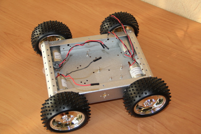
I note that the distance between two adjacent engines is quite large. This is an important point that is worth paying attention to for the following reason. The fact is that the selected engines without feedback. Just feed them a certain level of voltage and they spin at a certain speed. But the characteristics of the engines may differ, which will certainly lead to problems in a straight-line motion. If the scatter of the engines is small and the robot will be controlled only by the operator, who can always correct the movement, this may be a minor problem. But if the spread is significant or the robot will have to travel a long distance “in a straight line” in automatic mode, then it is necessary to provide feedback. There is a series of GM25-370 engines identical in design, on which Hall sensors are already installed. What it is?On the reverse side of the engine, on an elongated shaft, a disk is mounted, with a magnet placed on it, which will influence the Hall sensor. After each complete disk rotation, we receive a pulse signal, processing which can be set the number of revolutions per minute. Thus, a rather serious groundwork for the future is laid in our platform: it is possible to install motors with feedback, connect them to the power board that powers the sensors on them, and transfer telemetry signals to the control board — the control system can automatically level the speed of the engines.

I soldered the wires to the motors in accordance with the marks on them - on each motor near one of the two contacts there was a red dot. After receiving the engines, I checked them, but did not pay attention to the correctness of this marking. One of the engines, by the way, came with a marriage and did not scroll at all, the seller kindly sent me a replacement that reached me for at least a month. Subsequently, it turned out that one of the engines had the marking confused, but it does not matter - it is enough just to change the polarity of the connection of this engine to the power board. Looking ahead, I will say that the same situation happened with the connection of the "sides" - when giving the command "forward", the wheels on the right side spun forward, on the left side - back. This is also corrected by changing the polarity of the connection of the desired channel of the driver of the engines to the power board.Changing the polarity of the connection - no need to re-solder or rework, you just need to change the wires in places.
In order to prevent electrical contact between the electronics boards and the case, I cut plastic plates from the blister pack onto the bottom of the platform.
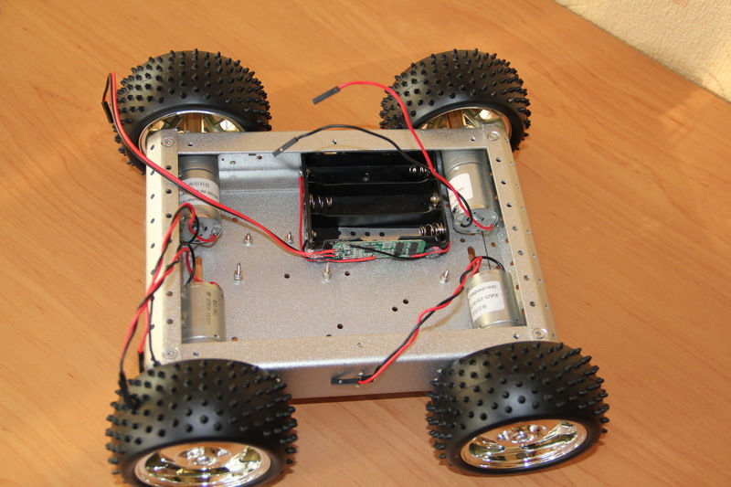
Install the battery pack. The plastic is very soft and literally sags under the screw head, even the puck does not save, so I had to use a long metal plate.
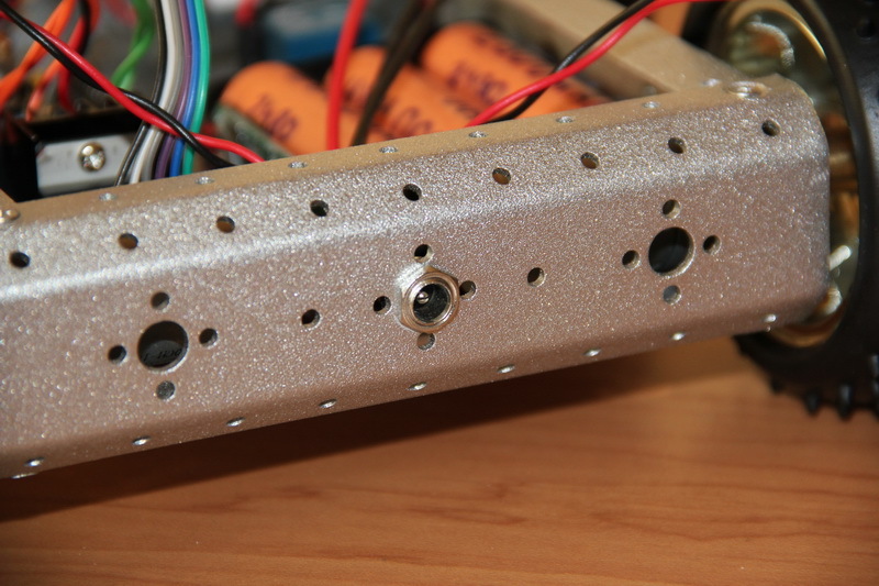
All our bolts and gadgets from the bottom slightly reduced ground clearance and look quite aesthetically pleasing.

Isolate the bottom in the places of installation of electronic boards. We also cut out a plastic strip on the metal plate in the battery pack, in order to prevent scratching the battery case against the screw head, lithium - this is serious!
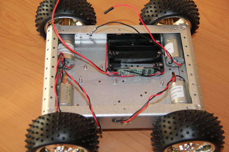
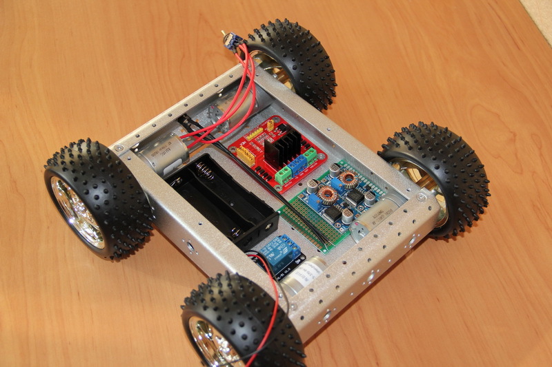
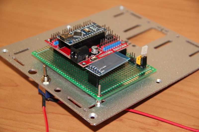
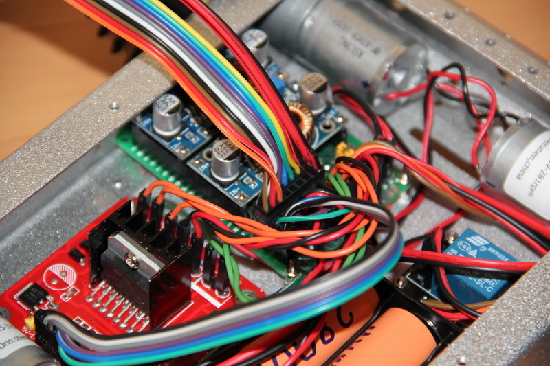
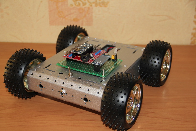
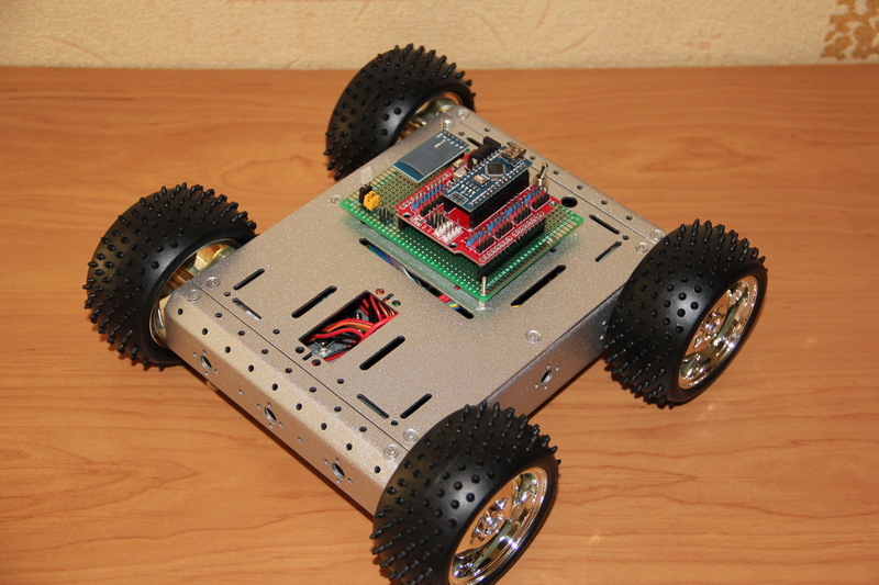
Install and fasten electronic boards and power connector.
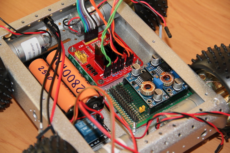
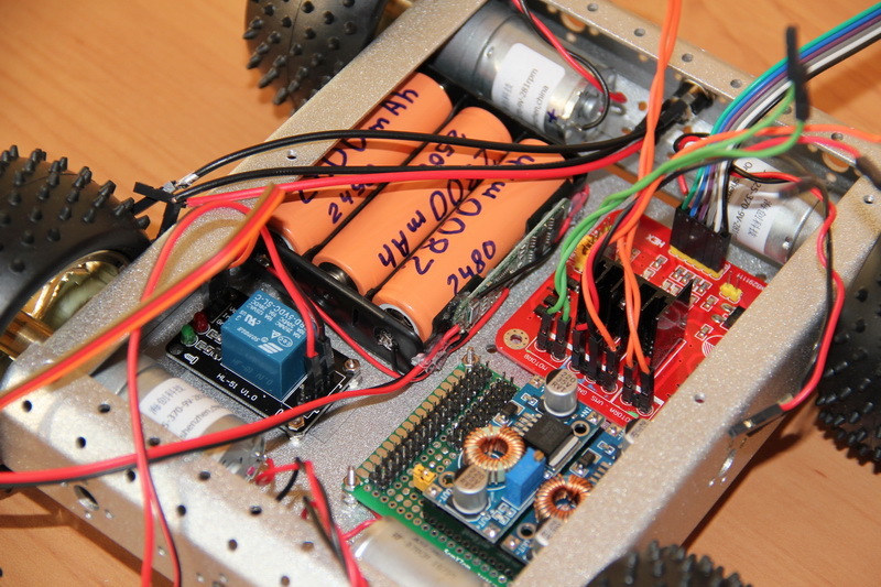
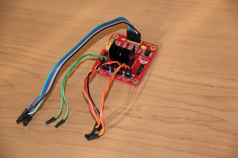
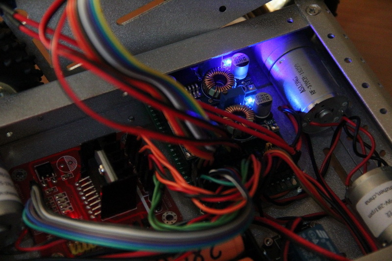
A nightmare, how many wires ... We connect the periphery to the power board.

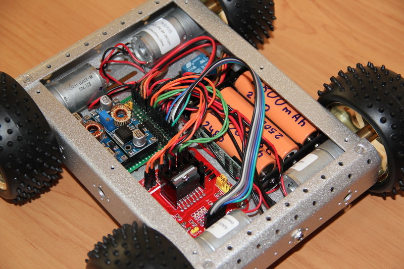
As you understand, in principle, the task is completed. The platform is received, everything turned out pretty well. To control the platform, you can use any microcontroller, FPGA, Arduino board, Intel Galileo, and more.
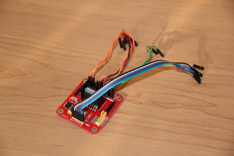
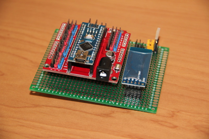
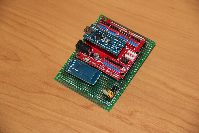
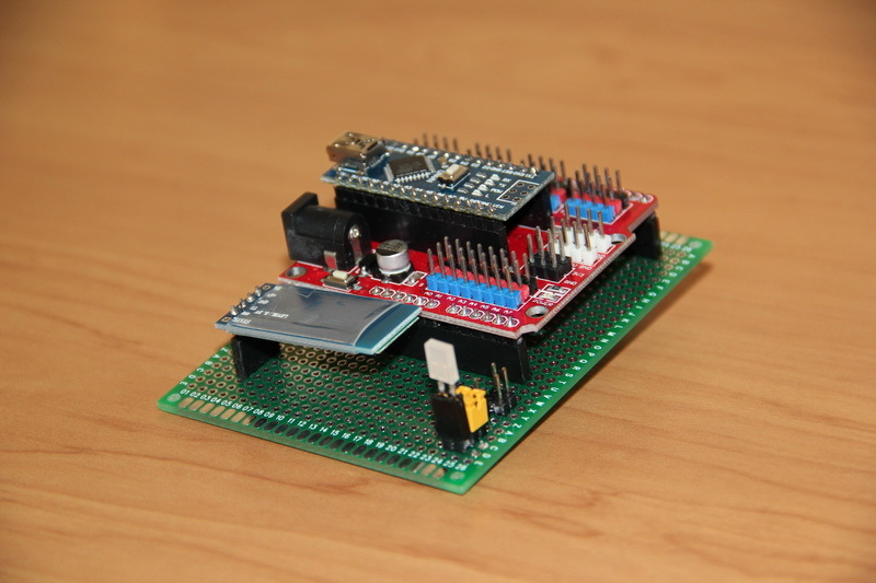
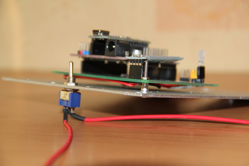
I chose an Arduino Nano board, found an inexpensive and convenient expansion card for connecting peripherals and a bluetooth module. The basic idea is to manage our platform from a smartphone via bluetooth. The expansion card, with its abundance of contacts for connecting external devices, will allow in the future to seamlessly connect the future periphery of the robot.
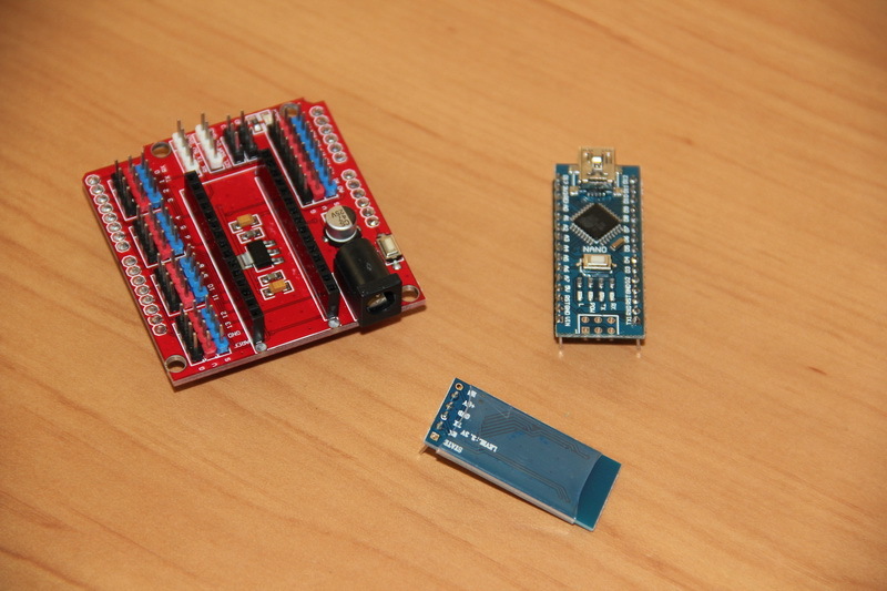
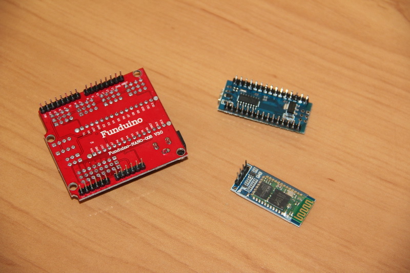
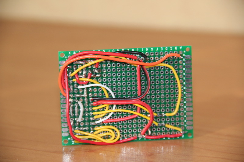
Now we need to develop and make a circuit board for this electronics. We will make a “sandwich”: a circuit board, on which a bluetooth module is installed and an expansion card, in which, in turn, a card with a microcontroller is installed.
Compared to the power board, this board is almost pure switching. In the center, a loop is connected to the 18-pin three-row connector that connects this control board to the power board. From this connector, the signals are divorced to the necessary contacts of the expansion card, which then get to the necessary, previously selected, contacts of the microcontroller. Also, the individual contacts on the board display a voltage of 5 V and Vbat. The board supplies power to the bluetooth module, its Rx / Tx inputs are connected to the Rx / Tx inputs of the Arduino Nano board via an expansion card. On the board is a removable bipolar LED, the purpose of which is the indication of all processes related to power. The LED can generate a green and red steady light, blink with a given frequency - this should be enough to indicate the normal voltage of the battery pack,its discharge, indication of the charging process and the health of the connected power source.
In order not to get confused about what and where to connect, I schematically drew the Arduino Nano board and distributed the signals for it.
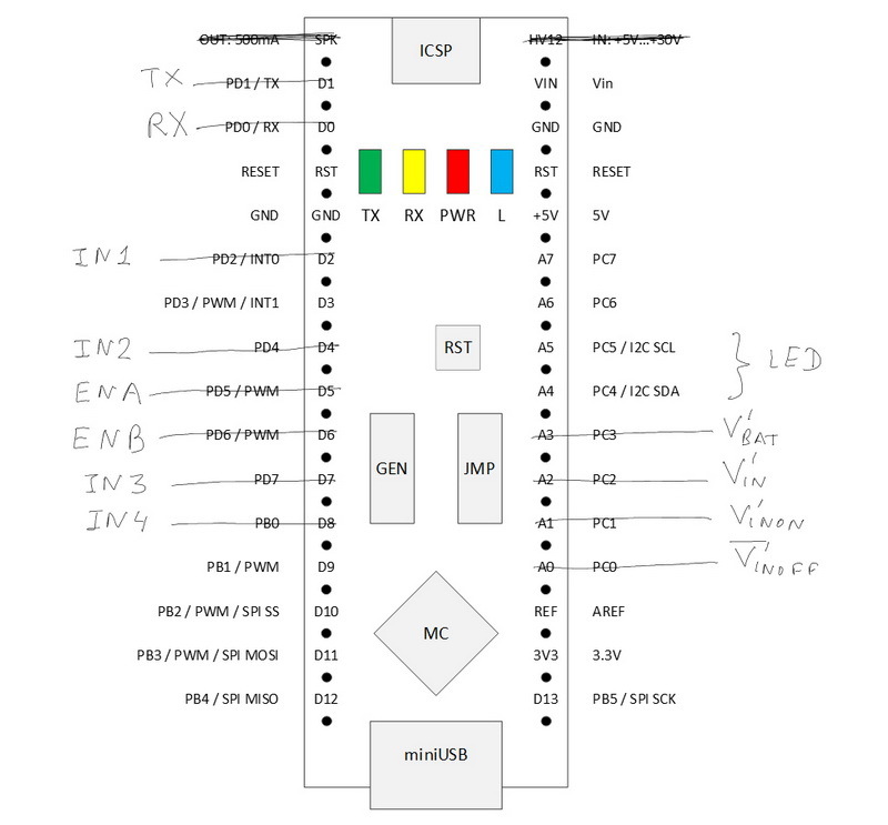
The Rx / Tx ports are occupied by the bluetooth module, which operates via the UART protocol. Signals IN1-IN4, if possible, are connected to digital ports — the polarity of these signals will determine the direction of rotation of the motors, and ENA / ENB to those ports that allow PWM signals to be output — these signals will set the rotational speed of the motors. The values of the platform telemetry signals will be digitized by the analog inputs A0-A3 of the Arduino Nano. The LED occupies ports A4 and A5, and it is connected via jumpers. The fact is that these two ports are needed for the simple organization of the I2C protocol and, if we need it, we can simply remove the jumpers. The LED can also be “thrown” onto other free ports or connected to the vacant ports A4 and A5 a port expansion module (for example,on the basis of the PCF8574T chip - will give an additional eight digital input / output ports (the module is controlled just by the I2C protocol), connect the LED to the pair of outputs. As a result of this distribution of the connection, the possibilities of seamless connection of SPI devices, the digitization of two more analog signals, the output of up to four PWM signals (for example, to control servo drives) were preserved. In general, I would like more free signals, but their number can be increased using PCF8574T. In the end, you can use another Arduino Nano or replace it with a more suitable platform for the required tasks - this solution provides a certain minimum.As a result of this distribution of the connection, the possibilities of seamless connection of SPI devices, the digitization of two more analog signals, the output of up to four PWM signals (for example, to control servo drives) were preserved. In general, I would like more free signals, but their number can be increased using PCF8574T. In the end, you can use another Arduino Nano or replace it with a more suitable platform for the required tasks - this solution provides a certain minimum.As a result of this distribution of the connection, the possibilities of seamless connection of SPI devices, the digitization of two more analog signals, the output of up to four PWM signals (for example, to control servo drives) were preserved. In general, I would like more free signals, but their number can be increased using PCF8574T. In the end, you can use another Arduino Nano or replace it with a more suitable platform for the required tasks - this solution provides a certain minimum.you can use another Arduino Nano or replace it with a more suitable platform for the required tasks - this solution provides a certain minimum.you can use another Arduino Nano or replace it with a more suitable platform for the required tasks - this solution provides a certain minimum.
Also, our board provides a simple power connection: there are 5 V power contacts and voltages from the battery pack (up to 12.6 V).
It is worth noting one nuance of the expansion card used for the Arduino Nano. In principle, the expansion card allows you to get on it Vbat. A voltage converter is installed on the expansion board, which lowers the input voltage to 5 V and supplies it to the Arduino Nano board, the converter of which lowers it to 3.3 V, and this voltage is already removed from the Arduino Nano board and divorced to the appropriate contacts of the expansion board. However, I did not do that and started up 5 V on the corresponding contact of the expansion card. In addition, the control LED on the expansion card does not glow at all, if the Arduino Nano is not installed, that is, this expansion card without the Arduino Nano, apparently, is practically inoperable. I did not understand the reasons, but I noted this moment.
We make this control board.


We install electronic boards on it.
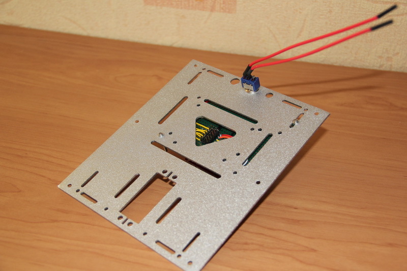
We prepare the seats for our fee. At the same time set the switch.
And we collect everything.
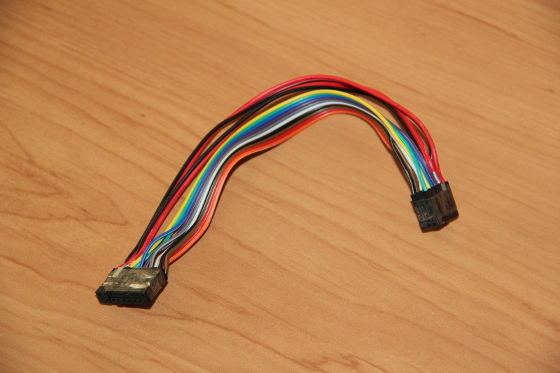
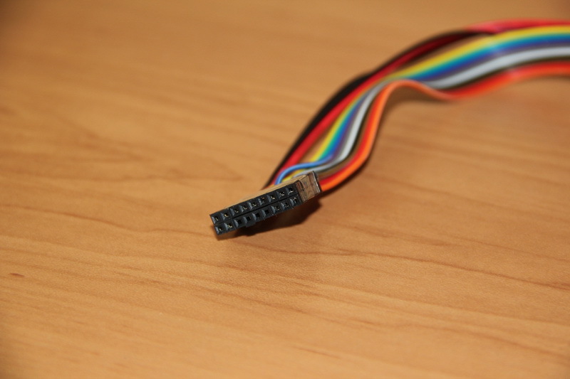
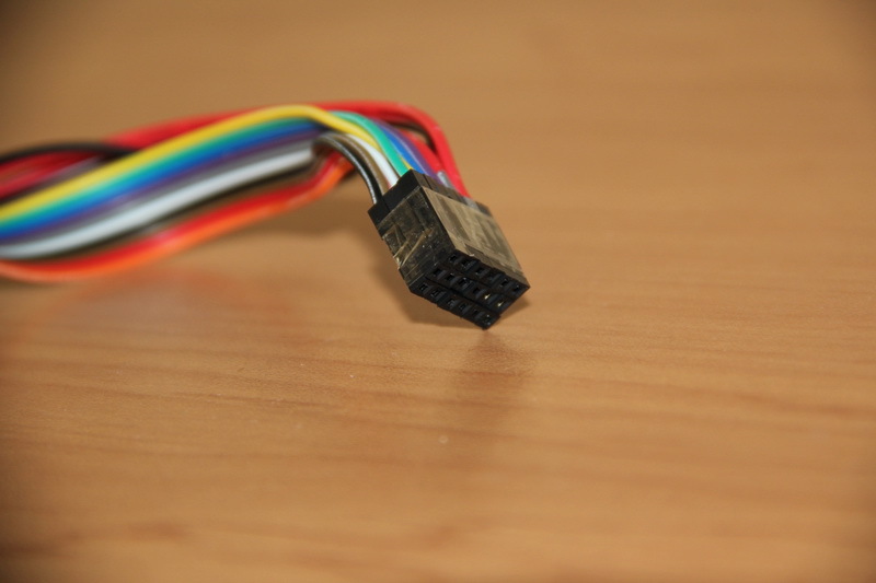
Now you need to make a cable to connect the two boards. Power connectors also solder for reliability. Correctly and very carefully check everything. 12 V should come to 12 V, and 5 V should go to 5 V. The pictures of the power and control circuit boards show “top view”, that is, if the boards are turned over, the contacts are swapped from the bottom, wiring side of the boards - this is necessary take into account in the manufacture of cable and probros appropriate wires in it. I made the connectors simply: first, a row of wires with BLS connectors was piled up and wrapped with adhesive tape for 2 times. Then all two / three rows gathered together and again tightly wrapped with tape. It turned out a whole and monolithic connector. Unplugged connector pins simply contained plastic BLS connectors without pins.
After the cable has been manufactured, all electronic boards are removed from the control board, and it is checked with a multimeter in the same way as the power board. We connect the control board with the power board and supply power. With the help of a multimeter, we carefully check the power contacts of all modules, we are curious about the voltages of telemetry signals - once again we make sure that everything is divorced correctly. You can not do this, self-confidently collect everything, turn on the power and find that the wires of 5 V and Vbat are somehow mixed up, of course, mysteriously, and the Arduino board and the bluetooth module burned in our place. But it is better not to repeat the mistakes of others.
In the photo you can see that one of the red power wires is tinted with silver. This is the designation of the conductor that transmits the voltage Vbat. When the device is assembled, it is useful to make "keys" for connection. For example, do not specifically unsolder one PLS contact on the connector, and spoil or hammer the return socket in the cable with a piece of insulation - in this case “fool protection” is realized, since then such a cable can be installed on the corresponding connector on the board only correctly, because otherwise it will not be established (the method does not give a 100% guarantee - there are a lot of pictures on the Internet, when especially persistent individuals still somehow manage to bypass such protection by applying enviable persistence and their remarkable strength). I usually tint the corresponding pins on the connectors.It would be useful on the power board to designate the input connectors of the DC / DC converters and tint the corresponding sockets on the board. This would eliminate the wrong installation of converters, and if you use several colors, it will eliminate the confusion of the boards of converters that form 5 V and 9 V. For the designation, you can use a bright female nail polish. This small rule helps a lot when assembling / disassembling a device under development at the stage of debugging and testing.This small rule helps a lot when assembling / disassembling a device under development at the stage of debugging and testing.This small rule helps a lot when assembling / disassembling a device under development at the stage of debugging and testing.
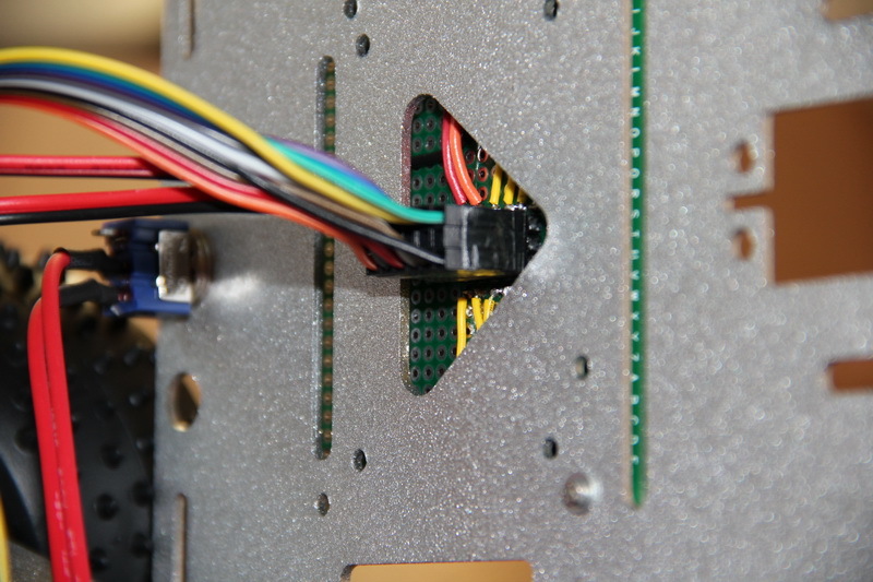
Connect the cable to the power board.

And to the microcontroller board.
Before we collect everything - we check the operation again - click the switch. And make sure that everything works.
There are two voltage converters.
The driver of engines works.
Power to the relay module.
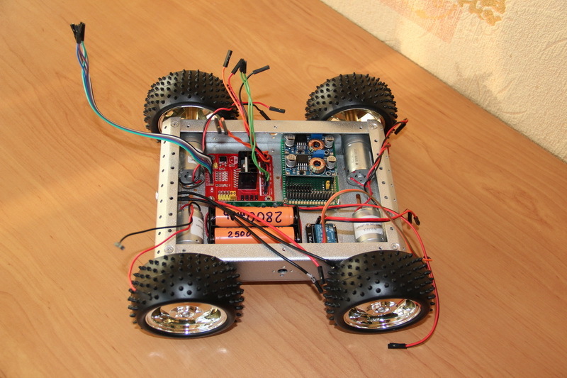
It's amazing - everything works. Putting it all together!
We check that after complete assembly everything is also operational.
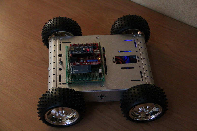
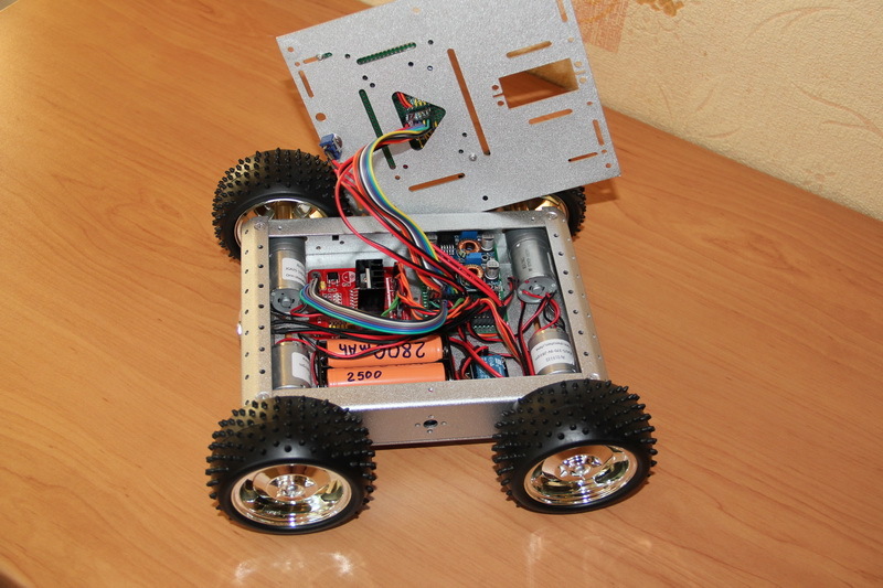
Here we have collected such handsome. Weigh the newborn.
Received 1.4 kg.
Usually, after finishing some work, the one who did it understands how it can be done even better. Do not immediately rush to redo everything, remembering in time that the best is the enemy of the good. But do not stop there. Virtually any work is 20 percent of creativity and 80 percent of the routine that needs to be done to get the finished product of labor. It is the routine that kills interest, desire, creativity. Therefore, if something is not immediately redone, then it is worth thinking: what can be improved in the future?
I would like to briefly return to the beginning of the article, by the time when we divided the platform into two parts and rendered the management fee "separately." At that time it seemed like a very balanced solution. However, looking at the ample contact field on the Arduino expansion board, we understand that a good half of these contacts cannot be used in the current implementation of the platform - we have occupied almost half of the I / O connectors on the Arduino board. And the microcontroller itself “turns” not just a program for issuing a pair of PWM signals to the motors, but provides full control over the internal and external power supply of the entire platform. It is worth thinking - maybe it is necessary to include a microcontroller in the composition of the motor compartment of our platform? Bluetooth "give away" to "supra-platform" electronics that will control the robot's devices,and think with her interface. You can organize the UART protocol (it takes two pins of the microcontroller) via which the data packet containing the direction and speed of the engines, as well as the general condition of the platform will be transmitted ... And you need to think carefully about the structure, since we don’t have much space in the engine compartment ... Although ... If you expand and move the relay ...
Well, that ended my long and sometimes boring story. Designed, manufactured and assembled only "hardware" - hardware platform. The next part of the work is software. But this does not mean that further work will be necessary only by a programmer. In the process of creating the firmware for the microcontroller and its debugging, it is sometimes necessary to take a multimeter, or even an oscilloscope, and understand what signal, where and in what form it comes. Usually, it is at the beginning of this stage, to a greater extent, errors and oversights of the “iron” design stage appear. Our device is very simple, so if something does not work, then the error will quickly be found. Can you imagine how to work with really complex schemes? There you need to be much more careful and careful.It will also be necessary to organize the control interface via bluetooth with a smartphone - to come up with some protocol of information interaction of the robot with the phone. And to develop software with which it is comfortable and convenient to control the robot. But all this is another story.
I don’t know how people who work can write an article in two or three days - it takes me from two to six weeks. Therefore, my performance is no more than two articles per year. It is clear that there is a rating of the article and the karma of the author, but I would like to more precisely evaluate your attitude to such material and its presentation, therefore voting in the polls below is welcome. The term of the survey - 1 year from the date of publication.
Familiar guys again turned to me with a request to help make the robot "more serious." This time it was decided not to make a full-fledged robot, but some kind of basic platform that would allow to design further robot functionality on it, possibly with variations, without being distracted by questions about the chassis, engines, power system and, ideally, local or remote system management.
')
The purpose of this post is to show the process of developing and manufacturing such a platform. Usually, articles on robotics show ready devices, demonstrating what has been done and how it works as a result. This is interesting, of course. But with great pleasure I read articles in which it is shown step by step exactly how it was done, why the description of some particular moments or thoughts. I will try to describe in detail how the moving platform was going at home. This article is a profile reading for recreation. I prepared the article itself, probably, more than three times more time than I was engaged in needlework. I do not pretend to be complete, high-tech, science-intensive, innovative and infallible ... But I hope that for someone it will help to take some first steps and show that modern modular electronics is not at all difficult, although not quite as simple as it seems. . "Uncles again play with cars instead of doing serious work." But you need to do something for those who can not grow. Caution - under the cut there will be a lot of text and indecently a lot of pictures.
Foreword
I have already done, or rather collected, a RASH1 robot. It is difficult to call this robot handmade, since the platform is absolutely assembled on ready-made components. Of interest is the control system of such a platform, built on the basis of a small router with the cyberWRT system, which allows you to control the robot from any device through a browser. I confess that the meaning of the work was more in demonstrating the development process itself from the point of view of methodology and documentation, rather than in direct production. On this occasion, in Habré, a measure of good faith, an almost conceptual article was written down, since I decided that since I tried to describe the development, I’d do it for everyone, especially the startup initially aimed at open source and the guys were not against such an initiative .
If you watch the video, then make sure that the Chinese motors for 300 rubles are very different and sometimes it is not easy to pick them up the same, especially if there are no others. And, if they turn unequally, the robot will not go straight. Although, by his desire once again to duck to the left, he did not leave a single household indifferent, such an effect is clearly undesirable. You can put the encoders and programmatically adjust the rotation of the wheels. If there are no encoders, then you can empirically calculate how much you need to slow down (lower the voltage level) a faster engine so that the robot drives straight and level. However, as the batteries / accumulators discharge, the characteristics of the fitted “operating point” will change and, at a different voltage, the motors behave quite differently - the robot will again begin to “take” in some direction. In addition, the control of the robot via cyberWRT is still not perfect - the connection was broken, sometimes the picture disappeared, I don’t remember exactly, it seems that the control of touch buttons did not work at all on Firefox. After reconnection to the robot, everything was restored, that is, it was repaired without rebooting the router, perhaps some kind of capriciousness in the computer / telephone-router-router_broken connection took place. It is worth noting that cyberWRT quite simply solves the issue of management organization, giving the opportunity to write your module and convert, roughly speaking, WEB on the one hand to the UART on the other. There is enough Russian-language information on the Internet, and there is also a fairly active community that can help sort out some issues. Well, the robot turned out more for demonstration and study, than for purely practical use. He was very fun and smartly traveled without the second floor, but he became noticeably sad when a router with a small USB hub and a video camera was added.
By itself, the assembly of the robot RASH1 completely allows beginners in robotics to take the first steps without focusing on the development of electronics, putting a minimum of effort with a soldering iron in their hands (there is a ready-made diluted board, which is easily untied) a self-made robot - I am sure that a normal robot engineer will not grow up on lightweight electronic designers alone. In principle, this is already enough: the resulting robot, and without control via cyberWRT, allows you to program your behavior. It is enough to understand Arduino ( circuit design and programming ), to master the concept of pulse-width modulation ( Ref. 1 , Ref. 2 ) and search the Internet for examples of the application of certain sensors.
For example, the basic firmware has an autonomous mode, which is activated by pressing a button on the robot and allows the robot to travel indoors, ideally without colliding with objects - a sonar (ultrasonic sensor) constantly monitors the situation in front of the robot and when it detects an obstacle, the robot stops and starts slightly heaped the reversal algorithm, the essence of which is to get random turns in order to triumphantly leave any trap out of the furniture cleverly arranged by people. You can add another sonar, improving the "vision" of the robot. You can connect the light sensor and, by its values, turn the “lights” of the robot on or off so that it is “more visible” in all dark corners under the tables and chairs. Or connect a motion sensor, for example, an inexpensive HC-SR501 (based on the BISS0001 chip) to teach the robot to hide from people. In general, there is a lot of scope for creativity, entertainment and knowledge of how electronics work at a “low” level.
After RASH1 I became interested and I made a RASH2 robot. This robot can already be classified as handmade. The purchase platform was taken as the base - the upper and lower glass-fiber laminate base, racks, motors are all a single set purchased in the “Great Chinese Internet”.
This robot has already developed its own electronics, which is made on a breadboard, to which connectors were soldered, and the role of tracks was performed by wiring. Power is supplied, not from AA batteries / rechargeable batteries, but from four lithium-ion batteries of size 18650. Servomotors are installed that allow the “head” of the robot to rotate in two planes. On the "head" of the robot is installed a video camera and sonar. In the automatic mode, the robot no longer needs to spin entirely - just “look around” with a sonar. The robot has the same "yellow" engines, like the previous one, and was originally conceived as a front-wheel drive, but then had to be redone to all-wheel drive because of absolutely no dynamics due to a decent weight. Encoders are already installed, but there is no special meaning in them, since the robot is quite heavy and the neighboring wheels on one side will slow down each other on their own. The control system is also built on the TL-MR3020 router with cyberWRT firmware.
Designing such a robot is perfect for those who want to gain experience of initial development and move on - self-developed electronics, complete soldering in its concept, design and own assembly, understanding of servo control ( article from Amperca ). On the Internet, you can find a similar, almost ready whale, which includes the necessary components - I did it and assembled it from sticks and ... in general, from what was at hand, periodically drilling through, undermining, sticking, screwing, even scotch taped - where do without him.
Thinking about a new robot
And now, now the new robot. What do we want from him?
We want the platform to be strong, load-carrying, with good maneuverability and ground clearance (clearance). We want to get a universal platform so as not to make a new one every time - the practice of life, however, usually proves otherwise - but as many developments begin, this is a normal and healthy desire. What is the image of a universal platform based on the requirements outlined above? Probably, this is a metal chassis, four engines with good power and big wheels. Obviously, it is better to close the engines in a separate closed compartment. In this engine compartment it would be nice to remove the driver for the engines, batteries, and some kind of power electronics. For example, the same DC / DC voltage converters, if present. I don’t want to change the batteries, just as I don’t want to pull out the batteries for recharging - everything is inside the platform and let it be able to recharge the batteries. For additional equipment, it will be possible to install metal racks and organize a “second floor” on the platform.
First of all, I divided the process of creating a full-fledged robot into two parts - the creation of some kind of universal platform and the creation of a robot based on this universal platform. This allows you not to think about the robot as a whole, thinking only about the junction of these two parts. Further we will talk only about the platform.
The second important point is the division of the platform itself into two parts. The first part has already been described - engines and power. But the engines need to be controlled. The control device will obviously be based on some kind of microcontroller - will it be put inside the engine compartment or not? The temptation is to make a completely ready-made stand-alone platform. But rationality suggests that the microcontroller is purely for controlling engines, plus some kind of interface for receiving commands - this is a wasteful computational expense. Therefore, it is better to isolate this part of the motor-power compartment.
As a result of thinking, the idea itself is made as follows. There is a closed platform, inside which are located the engines, the driver for the engines and the power source with the necessary power electronics. Obviously, it is better to have some kind of central switching card to which all these components will be connected. Also, this board will have the necessary electronics to obtain the necessary voltages. Let's call this board the power board. On the platform there is a board with a microcontroller, which is connected to the power board, receiving power from it and issuing commands for the engines to it. The microcontroller board can also control other robot equipment. This card will be called the control card.
Thus, the development process of the entire robot is conditionally “sawed” into two (three) parts: creating a platform (and its controls) and drawing an owl to create the rest of the body kit, which turns our platform into a full-fledged robot. The important point: while working on each stage, you can not think too much about others - think well enough of the “joints” between these parts.
Engines and power
After all these thoughts, the selection of components for the platform began.
After studying the proposals, I chose the engines of the JGA25-370 family.
Judging by the description of this series of engines, they have an operating voltage range of 3-36 V, nominal voltages of 6-24 V. These engines are available at different speeds, gearboxes and, accordingly, have different torques (0.1-10 kg * cm ). The size and attachment points of the entire series are the same, so we get a good universal solution in terms of future modifications - for a heavier and more heavy-duty platform, for example, you can install engines with lower speed, but greater torque. Typed operating voltage ratings for 6, 12 and 24 V motors. An important question is which nominal to choose?
In connection with the choice of engine power raises the question of the organization of autonomous power for our entire platform. I did not want to use batteries and rechargeable batteries of size AA or AAA. I wanted to use really capacious batteries. I chose lithium-ion batteries of size 18650, the capacity of which varies from 1000 mAh to 3500 mAh. I already have a positive experience with them, a good device for charging, and the batteries themselves are actively used in everyday life, that is, for me this is not a novelty.
Lithium-ion batteries have a sufficiently large number of charge / discharge cycles, a fast charge time with a relatively high current, no memory effect (although according to some sources, it is, although small, but there is), a low level of self-discharge, less weight than acidic or alkaline batteries, more capacity than NiMH batteries. However, it must be remembered that such batteries do not like excessive heat (probability of explosion) or excessive cooling (reduced capacity). They can not be deeply discharged, very quickly charged or discharged very quickly (we will not consider high-current batteries). If the battery is highly discharged, it will surely fail with the likelihood of depressurization while attempting to charge. If the tightness of the battery is impaired, then with strong currents there is a probability of lithium ignition, and it is no longer possible to put out such a battery with water - lithium reacts with water to form alkali and hydrogen. Why all these fears? In addition, the need to understand: the use of such batteries is a serious matter (we remember about the periodic experience from Samsung ).
The rated voltage of a single 18650 lithium-ion cell is 3.6–3.7 V. A fully charged cell produces 4.1–4.2 V. But with a minimum voltage it is more difficult — the final discharge voltage depends on the type of battery and this figure may fluctuate within 2.6-3.2 V. It is possible to discharge even lower, but this is a sure way to the rapid degradation of the battery. I decided to degrade the estimate of the voltage generated by the battery in the nominal-maximum range. Then it turns out that assemblies from two, three and four consecutive batteries give us ranges of 7.2-8.4 V, 10.8-12.6 V, 14.4-16.8 V. From this assembly we need to get two voltage - some kind of voltage to power the motors and 5 V to power the electronics. By assembling two batteries, it is possible to power the motors at 6 V, using a step-down DC / DC converter, but the difference between the minimum voltage value (when the battery is discharged to the nominal, it will be 7.2 V) and 6 V will be about 1.2 V, which can to be insufficient for stable operation of a DC / DC down converter - to avoid problems, you must have a voltage difference between its input and output of at least 2 V (in fact, it may be less for low dropout converters, but we will not be guided by them). An assembly of three elements is quite suitable for us; we obtain the required voltages by applying DC / DC downconverters. The engines can be powered to 9 V, then in the worst case we will get a difference of 1.8 V, which should be quite enough. The assembly of four elements is also suitable, but you need to understand that an additional battery is an extra weight and space, although a large energy intensity of the entire battery.
The second way to organize power is to use parallel connections of the same batteries and step-up DC / DC converter. Then from 3.6-4.2 V the voltage can be increased to 5 V for electronics and up to 6-9 V for motors. It seems that the capacity of such a battery assembly can be easily varied by adding new elements, but you should not forget that the batteries used must have similar capacity and internal resistance.
To charge / discharge serial or parallel batteries, there are special controller boards. Protection controllers protect the battery assembly from over-charging or discharging (voltage control), short-circuit, exceeding the permissible discharge current. When using such simple boards, an external power supply with a limited charging current is required. Charge / discharge controllers independently are able to charge batteries using the cc / cv method with charging current limitation. Advanced controllers for the serial connection of batteries can also provide individual charge for each battery - they balance batteries.
I chose the serial connection of batteries using a protection card and an external charger. In the future, such a simple control board can be replaced with a charge controller with balancing. Although, with parallel connection, balancing is not required, it is necessary to take into account that with strong wear of any single battery, the controller cannot detect this and this can be fraught with something. It should also take into account the fact that the modes of each battery will be different. For example, when removing the same power, batteries with a parallel connection will have to give a greater current than with a parallel connection.
Therefore, engines with a nominal voltage of 6 V and an operating range of 3-9 V are suitable. I chose a motor with a speed of 281 rpm and consumption, in idle mode, 80 mA. Under load, the speed sags up to 238 rpm, the current rises to 380 mA, while the engine produces a power of 2 W and develops a torque of 0.5 kg * cm. When the engine is stopped, the torque increases to 4 kg * cm, and the current reaches 900 mA. All these characteristics were taken from a tablet posted on the website of one of the sellers of goods, since I could not find a normal datasheet.
Case and assembly running
I ordered the following engines.
If you look at the photo, you can see the slots on the shafts protruding from the engines. For these engines was found a set of couplings and wheels.
Wheels with a diameter of 80 mm, rubber soft, studded.
The very basis I was going to make from wide aluminum corners (or something similar that can be found in hardware stores) with the help of which to make a “side” frame, which can be closed with some kind of light, strong metal plates. Holes are drilled in the right places and threads are cut as needed. However, at first I decided to look for what the Chinese industry has to offer. And I found a whale - a chassis kit for designing a robot that contained the body itself, the aforementioned engines, couplings and wheels, as well as the battery compartment for AA batteries, the power switch, the power socket and fasteners. The case itself has many holes, which logically makes it easier and their presence should minimize the amount of plumbing work.
Having estimated the size and volume of the internal space (in parallel, electronics was chosen for the platform, which should fit in this building), I ordered this kit. On incoming engines, as can be seen above, for some reason it is written JGA25-370-9v-281rpm. Why exactly 9v, when the nominal value of this subgroup is 6 V, I did not understand, but, probably, the Chinese know better what to write in order to sell better.
The case itself weighs almost 400 grams. What material it is made of, I find it difficult to answer, but it is unlike the pure aluminum.
Remove the cover and install the engines. The holes for the engines have a diameter just for the M3 screws, no reserve is left for the adjustment of the position, but, we must pay tribute, it did not cause any problems - the holes clearly coincide with the threads on the engine housing.
We install couplings.
And fasten the wheels.
The result was a finished platform with a ground clearance of about 23 mm.
The weight of the “idle” chassis was a little more than a kilogram. Remember the pictures with the measurement of the mass of individual parts? 393+ (58 + 85 + 20) * 4 = 1045 grams. Everything in the collection weighs 1057 grams. 12 grams added 16 bolts.
That turned out to be quite a pretty platform.
Electrical circuit
Here it is worth explaining an important point why this particular whale. The fact is that if we manufacture the case ourselves, then its internal volume can be made arbitrary. The purchased case provides us with a strictly fixed volume in which everything should fit. Ideally, more and stock to stay. This must be taken into account initially and be understood: whether the desired filling will fit in this body or not, and it will be necessary to either change the electronics or choose another body. Inside the case there will be installed: motors, battery, driver for motors, power board, on which some electronics will also be located - the same voltage converters.
It seems to be clear what exactly we will have inside. But how will it all connect? If you have an idea, but you can not create her image - you have no idea. In electronics, it turns out that there must be two images - a visual one, which we can already fully imagine, and an electrical one (in fact, there is also an algorithmic one - when the device behavior is signaled due to its hardware and / or software (firmware functionality) capabilities).
I spend a lot of time on the way to work. Generally speaking, with the right approach, a long way can be turned into a plus, reading books, watching / listening to popular science programs or audiobooks that you would never read, listen to or watch. Thanks to such conditions, I became a fan and listened to all the stories of the Model for assembly (so that there were no questions in the comments - an article on Wikipedia ). Robot-buoy was no exception and I thought out the schematic diagram of the platform and drew it on the road on the tablet .
The scheme is drawn in OneNote. The picture is clickable. Yes, I am ashamed - the concept does not look fundamental. For the last three weeks, I can’t take the time to fine-tune the article and the question has already arisen whether to publish anything at all or to postpone it for later. Decided to publish so, otherwise "for later" may be fraught. I will draw normal schemes - I will replace the pictures. On the other hand, this design looks in the style of the original DIY. At work or at home, when an idea is formed, at first an ordinary sheet of paper and a regular pencil are taken ...
Let's look at the concept of what we will have to connect with. Three 18650 batteries are connected to the D1 lithium-ion battery controller. The entire common ground circuit is connected to the output of the P-controller D1. The P + output, through fuse FU1 and switch SW, is connected to the DC / DC inputs of the D3 and D4 converters. Converter D3 generates a voltage for the motors, D4 - to power the entire electronics. The outputs of these converters are connected to the driver of the D5 engines to which the motors are connected. To the channel MA are connected the engines ML1, ML2 of the left side, and the MB - MR1, MR2 of the right side. Two-channel driver, this means that it will be possible to control two groups of engines (channels A and B), but not individually each engine. The ports ENA, ENB, IN1-IN4 are used to control the speed and direction of rotation of the motors. The resistive chain that forms the voltage Vbat 'is chosen so as to form in the range 0 ... 5 V the telemetry of the voltage Vbat of the battery pack. If Vbat = 13 V (which should not be, since the battery pack can produce a maximum of 12.6V, but I was a little reinsured), then Vbat '= 3.94 V (that is, the value is guaranteed not to go beyond 5 V). The current flowing through the resistive chain at 12 V will be equal to 3.6 mA, and I considered these losses acceptable (about 0.1% with a battery capacity of 3000 mAh). A socket for external power supply is connected to the input of the D1 controller. But, we see according to the scheme that it is connected through the D2 relay.
First I want to clarify the presence of a 10 kOhm resistor that pulls one of the pins in the power connector to a voltage of 5 V. We have a power connector with three outputs. A pair of outputs transmit the power supply voltage. The third output is informational. It is closed to the negative output (it is connected to the “ground”) if there is no plug in the socket and it opens if the plug is inserted into the socket. Thus, we get the Vinon 'telemetry signal about connecting the power supply: if the voltage Vinon' = 0, then the external power is not connected, if Vinon '= 5 V is connected. A 10 kΩ resistor pulls the output to 5 V. When the plug is connected, a current of 0.5 mA will flow through the resistor, which is quite acceptable.
When an external source is connected through a normally-closed relay D2 and fuse FU1, the batteries will begin charging. A normally closed relay - this means - its outputs are always closed and open only when voltage is applied to the control contact. Why relay D2? Suppose we do not have this relay. If the power supply unit is connected to the platform, but you forget to plug it in - how does the microcontroller board know if the battery pack is charging now or not? And if the power source is plugged in, but does not give a voltage? Or does it work, but the power supply produces only 10V instead of the prescribed 12V? And, if I connected such a source (which only gives 10 V) to the battery, which is not yet discharged to the end and gives 11 V, then how do I know that the 11 V is formed by the battery pack (which actually does not produce above 10V) or external source? For such situations, the algorithm was considered, for which a relay was required. About connecting an external power supply, we learn from Vinon 'telemetry. Turning off the relay and look at Vin 'telemetry. If it suits and this voltage is in the expected range, then turn on the relay and signal the process of charging. If not satisfied - do not turn on the relay and signal the malfunction. Let the onboard control board, not the platform, deal with the process of analysis and indication. To do this, we will give it all the necessary voltages and a control signal for the Vinoff relay. The control input of the relay module through a 10 kΩ resistor is pulled up to 5 V, ensuring the relay is constantly turned on. When 0 V is applied to this input, the relay will turn off.
But why, precisely, the antediluvian mechanical relay? After all, you can put a MOSFET transistor. Such an idea was, but it had to be abandoned. Modern MIS transistors have low resistance (tens of millimeters) in the open state and with a current of 2-5 A there will not be a very significant voltage drop and, as a result, heating - a small power can dissipate the transistor case itself even without a radiator. But all this concerns the scheme in which such a digital key will control the connection of the power source to the passive load. We put a transistor between two sources, as a result of which the voltage difference between the drain and the source can be significant, which will lead to increased heat generation and the transistor will be very hot. Also, for opening or locking the transistor, it will be necessary to make a control circuit (driver), because the control voltage level from the microcontroller board is 5 V, which is not enough to create a gate-source voltage difference to control the transistor (for controlling the transistor, for example, IRFZ44N we will have apply on his shutter 8-12 V in order to open it). Whether business - the ready module of the relay which needs to be simply connected and which if it is closed, then with guarantee connects an exit to an entrance without any troubles.
Thus, we have turned out not just a switching board, but a full-fledged power board. On the board, DC / DC converters, resistive circuits, a fuse and a bunch of connectors for connecting electronics are installed. Structurally, there are two connectors. The CON1 connector to which the battery pack will be connected, the power switch / button, the power connector, the relay module, the motors, the motor driver board are all peripherals inside the platform. And the CON2 connector, the purpose of which is the connection to the control board. The telemetry and control signals, voltages of 5 V are output to this connector, and it is also useful to “push” the voltage from the Vbat battery pack — we enable the “higher level” to organize our power channels with different voltages, for example, 6 V to power the servo drives.
Chassis electronics
Electronics was chosen in parallel with the development of the electrical circuit of the device.
The power socket with the tumbler went into the business from the received chassis kit. A driver for L298N chip-based motors, XL4005 DC / DC converters, an unnamed relay module, a battery compartment, and a circuit board with dimensions of 50x70 mm and pitch of 2.54 mm were selected and purchased.
In addition, we still need the following materials.
At the top of the photo you can see several long pin connectors with a pitch of 2.54 mm, as well as sockets, below are metal contacts on the cable, to the left are sockets for them, to the right are screws, nuts and M2 washers. Connectors on the board and the cable in different stores are called differently. For historical reasons, I call the pin connectors for the PLS board, the jacks on the board are PBS, and the cable connectors are BLS. On the Internet on foreign sites, such connectors are searched on request of the "2.54mm connector" or "dupont connector" type. In addition, you will need a variety of consumables - solder, flux, wires, and so on, as well as a set of hand tools - nippers, tweezers, screwdrivers, etc. - usually those who do DIY at least ( Do It Yourself do it yourself).
Before ordering the electronics and the case, I figured that the selected electronics should fit in the internal space without any problems. The time has come to check it out: we arrange the electronics and mark future seats.
Now we are going to prepare the boards.
I started with the battery pack. The controller of lithium-ion batteries was “planted” on hot melt glue and the terminals of the contacts were soldered to it in accordance with the circuit diagram. I think readers will be interested in what and what tool was done, so at the end of the article, under the spoiler, I posted pictures of some used equipment with my brief comments. Hotmelt adhesive was applied with a thermogun. However, before that I had to work on, so to say, increase the reliability of this compartment. I will warn everyone who is going to do something - it is better not to make my mistake and take more durable battery compartments. At one time I could not find such compartments at retail, and when I did, I scored a lot of them for the joy of spiritual simplicity. And with them everything is not so simple. Because in this compartment, batteries with flat, non-protruding plus platforms simply do not reach the contact. In addition, all spring-loaded contacts rotate, the contact is bad. So I had to screw in the M2 bolts, bite off the excess, tighten the nuts and tighten to improve the contact. But this seemed to me a little, and I also carefully soldered all the connections. Because if something is done, then it must be reliable, so that it does not cause problems in the future and then do not come back to it again.
It should be noted that for lithium-ion batteries using a regular controller without balancing. This means that when charging one of the three batteries, the controller will certainly interrupt the charge of all batteries. In fact, it’s just a low-discharge protection board and rechargeable batteries and control of the discharge current. Therefore, it is desirable to use batteries with the same real capacity. If you use a controller with balancing, then the selection for capacity is less critical and the batteries will be used more efficiently, but such controllers are more expensive and take up more space. How to choose batteries with the same real capacity? After all, having bought the same batteries from the same series even from brands, the capacity can vary by 5-10%, and Chinese batteries with inscriptions 6000-8000 mAh, in general, are batteries with an unknown capacity. I used the OPUS BT-C3100 charger, which is quite popular in my environment, to measure real capacities. With the help of it, 12 purchased batteries were checked and three were selected, the capacity spread of which is minimal and does not exceed a few percent. The capacity of LG LGABC21865 batteries was declared at 2800 mAh, but in reality it ranged from 2400-2500 mAh (tested at 700 mA).
A small digression in the form of thinking. The charger considered us the capacity of the batteries, taking into account their charge up to 4.2 V and discharge, if I am not mistaken for the OPUS BT-C3100, up to 2.8 V. In our case, the batteries should not be less than the nominal 3.5-3, 7 V. That is, our battery capacity is much lower than the measured one. This must be taken into account. Perhaps in the future, it is worth thinking about a battery pack of four batteries. Is it possible to simply replace the battery pack and power supply to charge it? Let's estimate. We will have a voltage range of 14.4-16.8 V. The voltage transducers operate with an input voltage of up to 32 V. Resistive dividers will give us a voltage range of telemetry signals of 4.3-5.1 V, which is slightly above the upper range 0-5 Q. But it can be parried at the level of the control board - if the telemetry voltage is 5 V, then the battery pack will be almost charged after a while. On the other hand, if you reduce the voltage on the motors to 6-7 V, you can discharge the existing battery pack more effectively and use the batteries more efficiently - in this case, you only need to adjust one voltage converter. At first glance, there is room for future research without changing the hardware at all, and how to interpret telemetry signals depending on the installed battery pack - let it be solved at the level of the control board, that is, you can not think about it yet.
I cleaned the output wires from the resulting battery pack with special tongs (stripper) and pressed them into metal contacts using crimping pliers (crimper), for reliability I lost and put plastic cases on them, getting BLS connectors. When soldering, a soldering station was used, POS-61 without rosin was used as a solder, and FluxPlus NC-D500 was used as a flux.
After assembling the battery pack and installing batteries into it, it will not issue anything. Many controllers of lithium-ion batteries are arranged this way - they de-energize the load during a short-circuit, a strong discharge, and an excess of discharge current. In order to “reset” the protection and bring the battery pack into operation, it must be fed 12-12.6 V to the + P / -P contacts. The same should be done after the first connection of the batteries to the controller. After that, you can make sure that the unit provides voltage if the batteries are properly connected to the controller.
To charge such battery assemblies, there are power supplies with an output voltage of 12.6 V (3x4.2 V). With such a power supply, the batteries will be used more efficiently, although you can also use power supplies with a nominal value of 12 V. I already have such a power supply with an output of 12.6 V and a current of 5 A. If a similar source is purchased, then you should make sure that He claimed characteristics. The simplest test is to test load capacity. For this, I used ceramic resistors of 1 Ohm 10 W and 4.7 Ohm 10 Watts. Having assembled a 2.5-ohm assembly of such resistors, I connected a power supply to it and measured the voltage at its output. With a rated current of 12.6 / 2.5 = 5, my power supply produced 12.6 V, which is an excellent result. Chinese power supplies, on which something is written, such as - 12V3A, often begin to "sink" by 10-20% with a load of only about 1 A.
By analogy, a switch and a power socket were prepared.
The terminal block was removed from the relay module using a hair dryer and PLS contacts were soldered. To connect this module to the power board, I manufactured the wires — stripped, crimped, and soldered the power wires (through which the power connector and battery pack will connect) with a cross section of 18-20 AWG. And for management I used the wires I had, with thinner conductors, which are easily searched for under the name “Dupont”.
The same was done with the engine driver.
On the DC / DC converters were soldered "legs". It is worth mentioning that these contacts are made of a metal that is well soldered only by the active flux. Then, instead of FluxPlus, I use LTI-120, followed by wiping the soldering spots with a cloth moistened with isopropanol, to remove any remaining flux.
Now we make our board with electronics. For a start, it's nice to imagine in general how and what will be connected on the board. That is, try to draw a circuit board.
[Power Board]
Guess where I came up with and “licked” this board? We see two connectors on the board, two voltage converters. There was an additional jumper (removable jumper), which can be installed by removing the fuse from the electrical circuit - I did this specifically because of the banal absence of a fuse at the time of manufacture of the board.
Wiring a board is quite tedious and painstaking work. For power, I used 18-20 AWG wires, for other signals - 26-30 AWG. Why exactly the breadboard and the trouble with the wiring? Because we still have only the first prototype. Something can change, so rewiring the wiring is easier than cutting the tracks and soldering any jumpers on the finished printed circuit board. It takes time to make a printed circuit board, dilute it, make a mask, etch it, drill it out, tin it, unsolder it is unlikely that this will take less time than making a board with “wiring”. Although the PCB will be more reliable, and look - more professional.
From these considerations, the DC / DC converters modules are not unsoldered on the board, but are made in the form of removable modules, ideally, after the initial debugging, they should be additionally fastened to the connector, for example, by dripping hot melt. Not bad in the same way to increase the reliability of the connection of all connectors. But while we have a prototype, it is more convenient for us to make everything removable so that in the course of future debugging we can have free access to any important node and facilitate its replacement if necessary.
After the board is manufactured, it is imperative to check the received for compliance with the circuit and wiring diagrams. Using a multimeter, I check the inputs and outputs for a short circuit (it is better not to “ring” the contacts, but to measure their resistance, as in the case of an erroneous manufacturing or design, for example, a resistance of one hundred ohms can be formed on the input, which may not “ring out” ", But its presence will be an error in the circuit and can cause great trouble), and also make sure that everything is connected as it should be inside the board.
After checking before assembly, you should make sure that the board will work normally when all the peripherals are connected. To do this, you must first connect the battery pack, the power switch and click the switch. The LEDs on the voltage converters should light up and not burn anything. As long as nothing is connected, it is necessary to adjust the output voltage of the converters. Then the power is turned off, the relay module is connected and power is applied again. Thus, all peripherals are connected in stages and under control.
Installation and connection of platform electronics
Electronics is ready. Now you need to install it. Remember, marked the board of electronic boards?The holes are drilled in the right places with a cordless screwdriver. Then polished with a minidrels with a grinding nozzle. M2 screws are screwed into the holes. Under the screws and nuts must be placed washers. In addition, I screwed on the second nut - the lock nut will provide a more reliable threaded connection and reduce the likelihood of its unwinding. We make the machine.
I note that the distance between two adjacent engines is quite large. This is an important point that is worth paying attention to for the following reason. The fact is that the selected engines without feedback. Just feed them a certain level of voltage and they spin at a certain speed. But the characteristics of the engines may differ, which will certainly lead to problems in a straight-line motion. If the scatter of the engines is small and the robot will be controlled only by the operator, who can always correct the movement, this may be a minor problem. But if the spread is significant or the robot will have to travel a long distance “in a straight line” in automatic mode, then it is necessary to provide feedback. There is a series of GM25-370 engines identical in design, on which Hall sensors are already installed. What it is?On the reverse side of the engine, on an elongated shaft, a disk is mounted, with a magnet placed on it, which will influence the Hall sensor. After each complete disk rotation, we receive a pulse signal, processing which can be set the number of revolutions per minute. Thus, a rather serious groundwork for the future is laid in our platform: it is possible to install motors with feedback, connect them to the power board that powers the sensors on them, and transfer telemetry signals to the control board — the control system can automatically level the speed of the engines.
I soldered the wires to the motors in accordance with the marks on them - on each motor near one of the two contacts there was a red dot. After receiving the engines, I checked them, but did not pay attention to the correctness of this marking. One of the engines, by the way, came with a marriage and did not scroll at all, the seller kindly sent me a replacement that reached me for at least a month. Subsequently, it turned out that one of the engines had the marking confused, but it does not matter - it is enough just to change the polarity of the connection of this engine to the power board. Looking ahead, I will say that the same situation happened with the connection of the "sides" - when giving the command "forward", the wheels on the right side spun forward, on the left side - back. This is also corrected by changing the polarity of the connection of the desired channel of the driver of the engines to the power board.Changing the polarity of the connection - no need to re-solder or rework, you just need to change the wires in places.
In order to prevent electrical contact between the electronics boards and the case, I cut plastic plates from the blister pack onto the bottom of the platform.
Install the battery pack. The plastic is very soft and literally sags under the screw head, even the puck does not save, so I had to use a long metal plate.
All our bolts and gadgets from the bottom slightly reduced ground clearance and look quite aesthetically pleasing.
Isolate the bottom in the places of installation of electronic boards. We also cut out a plastic strip on the metal plate in the battery pack, in order to prevent scratching the battery case against the screw head, lithium - this is serious!
Install and fasten electronic boards and power connector.
A nightmare, how many wires ... We connect the periphery to the power board.
Platform Control Electronics
As you understand, in principle, the task is completed. The platform is received, everything turned out pretty well. To control the platform, you can use any microcontroller, FPGA, Arduino board, Intel Galileo, and more.
I chose an Arduino Nano board, found an inexpensive and convenient expansion card for connecting peripherals and a bluetooth module. The basic idea is to manage our platform from a smartphone via bluetooth. The expansion card, with its abundance of contacts for connecting external devices, will allow in the future to seamlessly connect the future periphery of the robot.
Now we need to develop and make a circuit board for this electronics. We will make a “sandwich”: a circuit board, on which a bluetooth module is installed and an expansion card, in which, in turn, a card with a microcontroller is installed.
Compared to the power board, this board is almost pure switching. In the center, a loop is connected to the 18-pin three-row connector that connects this control board to the power board. From this connector, the signals are divorced to the necessary contacts of the expansion card, which then get to the necessary, previously selected, contacts of the microcontroller. Also, the individual contacts on the board display a voltage of 5 V and Vbat. The board supplies power to the bluetooth module, its Rx / Tx inputs are connected to the Rx / Tx inputs of the Arduino Nano board via an expansion card. On the board is a removable bipolar LED, the purpose of which is the indication of all processes related to power. The LED can generate a green and red steady light, blink with a given frequency - this should be enough to indicate the normal voltage of the battery pack,its discharge, indication of the charging process and the health of the connected power source.
In order not to get confused about what and where to connect, I schematically drew the Arduino Nano board and distributed the signals for it.
The Rx / Tx ports are occupied by the bluetooth module, which operates via the UART protocol. Signals IN1-IN4, if possible, are connected to digital ports — the polarity of these signals will determine the direction of rotation of the motors, and ENA / ENB to those ports that allow PWM signals to be output — these signals will set the rotational speed of the motors. The values of the platform telemetry signals will be digitized by the analog inputs A0-A3 of the Arduino Nano. The LED occupies ports A4 and A5, and it is connected via jumpers. The fact is that these two ports are needed for the simple organization of the I2C protocol and, if we need it, we can simply remove the jumpers. The LED can also be “thrown” onto other free ports or connected to the vacant ports A4 and A5 a port expansion module (for example,on the basis of the PCF8574T chip - will give an additional eight digital input / output ports (the module is controlled just by the I2C protocol), connect the LED to the pair of outputs. As a result of this distribution of the connection, the possibilities of seamless connection of SPI devices, the digitization of two more analog signals, the output of up to four PWM signals (for example, to control servo drives) were preserved. In general, I would like more free signals, but their number can be increased using PCF8574T. In the end, you can use another Arduino Nano or replace it with a more suitable platform for the required tasks - this solution provides a certain minimum.As a result of this distribution of the connection, the possibilities of seamless connection of SPI devices, the digitization of two more analog signals, the output of up to four PWM signals (for example, to control servo drives) were preserved. In general, I would like more free signals, but their number can be increased using PCF8574T. In the end, you can use another Arduino Nano or replace it with a more suitable platform for the required tasks - this solution provides a certain minimum.As a result of this distribution of the connection, the possibilities of seamless connection of SPI devices, the digitization of two more analog signals, the output of up to four PWM signals (for example, to control servo drives) were preserved. In general, I would like more free signals, but their number can be increased using PCF8574T. In the end, you can use another Arduino Nano or replace it with a more suitable platform for the required tasks - this solution provides a certain minimum.you can use another Arduino Nano or replace it with a more suitable platform for the required tasks - this solution provides a certain minimum.you can use another Arduino Nano or replace it with a more suitable platform for the required tasks - this solution provides a certain minimum.
Also, our board provides a simple power connection: there are 5 V power contacts and voltages from the battery pack (up to 12.6 V).
It is worth noting one nuance of the expansion card used for the Arduino Nano. In principle, the expansion card allows you to get on it Vbat. A voltage converter is installed on the expansion board, which lowers the input voltage to 5 V and supplies it to the Arduino Nano board, the converter of which lowers it to 3.3 V, and this voltage is already removed from the Arduino Nano board and divorced to the appropriate contacts of the expansion board. However, I did not do that and started up 5 V on the corresponding contact of the expansion card. In addition, the control LED on the expansion card does not glow at all, if the Arduino Nano is not installed, that is, this expansion card without the Arduino Nano, apparently, is practically inoperable. I did not understand the reasons, but I noted this moment.
We make this control board.
We install electronic boards on it.
We prepare the seats for our fee. At the same time set the switch.
And we collect everything.
Now you need to make a cable to connect the two boards. Power connectors also solder for reliability. Correctly and very carefully check everything. 12 V should come to 12 V, and 5 V should go to 5 V. The pictures of the power and control circuit boards show “top view”, that is, if the boards are turned over, the contacts are swapped from the bottom, wiring side of the boards - this is necessary take into account in the manufacture of cable and probros appropriate wires in it. I made the connectors simply: first, a row of wires with BLS connectors was piled up and wrapped with adhesive tape for 2 times. Then all two / three rows gathered together and again tightly wrapped with tape. It turned out a whole and monolithic connector. Unplugged connector pins simply contained plastic BLS connectors without pins.
After the cable has been manufactured, all electronic boards are removed from the control board, and it is checked with a multimeter in the same way as the power board. We connect the control board with the power board and supply power. With the help of a multimeter, we carefully check the power contacts of all modules, we are curious about the voltages of telemetry signals - once again we make sure that everything is divorced correctly. You can not do this, self-confidently collect everything, turn on the power and find that the wires of 5 V and Vbat are somehow mixed up, of course, mysteriously, and the Arduino board and the bluetooth module burned in our place. But it is better not to repeat the mistakes of others.
In the photo you can see that one of the red power wires is tinted with silver. This is the designation of the conductor that transmits the voltage Vbat. When the device is assembled, it is useful to make "keys" for connection. For example, do not specifically unsolder one PLS contact on the connector, and spoil or hammer the return socket in the cable with a piece of insulation - in this case “fool protection” is realized, since then such a cable can be installed on the corresponding connector on the board only correctly, because otherwise it will not be established (the method does not give a 100% guarantee - there are a lot of pictures on the Internet, when especially persistent individuals still somehow manage to bypass such protection by applying enviable persistence and their remarkable strength). I usually tint the corresponding pins on the connectors.It would be useful on the power board to designate the input connectors of the DC / DC converters and tint the corresponding sockets on the board. This would eliminate the wrong installation of converters, and if you use several colors, it will eliminate the confusion of the boards of converters that form 5 V and 9 V. For the designation, you can use a bright female nail polish. This small rule helps a lot when assembling / disassembling a device under development at the stage of debugging and testing.This small rule helps a lot when assembling / disassembling a device under development at the stage of debugging and testing.This small rule helps a lot when assembling / disassembling a device under development at the stage of debugging and testing.
Connect the cable to the power board.
And to the microcontroller board.
Before we collect everything - we check the operation again - click the switch. And make sure that everything works.
There are two voltage converters.
The driver of engines works.
Power to the relay module.
It's amazing - everything works. Putting it all together!
We check that after complete assembly everything is also operational.
Here we have collected such handsome. Weigh the newborn.
Received 1.4 kg.
Usually, after finishing some work, the one who did it understands how it can be done even better. Do not immediately rush to redo everything, remembering in time that the best is the enemy of the good. But do not stop there. Virtually any work is 20 percent of creativity and 80 percent of the routine that needs to be done to get the finished product of labor. It is the routine that kills interest, desire, creativity. Therefore, if something is not immediately redone, then it is worth thinking: what can be improved in the future?
I would like to briefly return to the beginning of the article, by the time when we divided the platform into two parts and rendered the management fee "separately." At that time it seemed like a very balanced solution. However, looking at the ample contact field on the Arduino expansion board, we understand that a good half of these contacts cannot be used in the current implementation of the platform - we have occupied almost half of the I / O connectors on the Arduino board. And the microcontroller itself “turns” not just a program for issuing a pair of PWM signals to the motors, but provides full control over the internal and external power supply of the entire platform. It is worth thinking - maybe it is necessary to include a microcontroller in the composition of the motor compartment of our platform? Bluetooth "give away" to "supra-platform" electronics that will control the robot's devices,and think with her interface. You can organize the UART protocol (it takes two pins of the microcontroller) via which the data packet containing the direction and speed of the engines, as well as the general condition of the platform will be transmitted ... And you need to think carefully about the structure, since we don’t have much space in the engine compartment ... Although ... If you expand and move the relay ...
Well, that ended my long and sometimes boring story. Designed, manufactured and assembled only "hardware" - hardware platform. The next part of the work is software. But this does not mean that further work will be necessary only by a programmer. In the process of creating the firmware for the microcontroller and its debugging, it is sometimes necessary to take a multimeter, or even an oscilloscope, and understand what signal, where and in what form it comes. Usually, it is at the beginning of this stage, to a greater extent, errors and oversights of the “iron” design stage appear. Our device is very simple, so if something does not work, then the error will quickly be found. Can you imagine how to work with really complex schemes? There you need to be much more careful and careful.It will also be necessary to organize the control interface via bluetooth with a smartphone - to come up with some protocol of information interaction of the robot with the phone. And to develop software with which it is comfortable and convenient to control the robot. But all this is another story.
Some used tools and equipment
BOSCH GluePen. Glue gun. Bosch – . . 18650, , . (15 ) , – . . – : 7 , 150…170 ( DREMEL GG01 GG03).

GROSS 17718. (). KBT WS-04A, 1--1.

HT-202A. ().

Solomon SL-30. . 24. . .
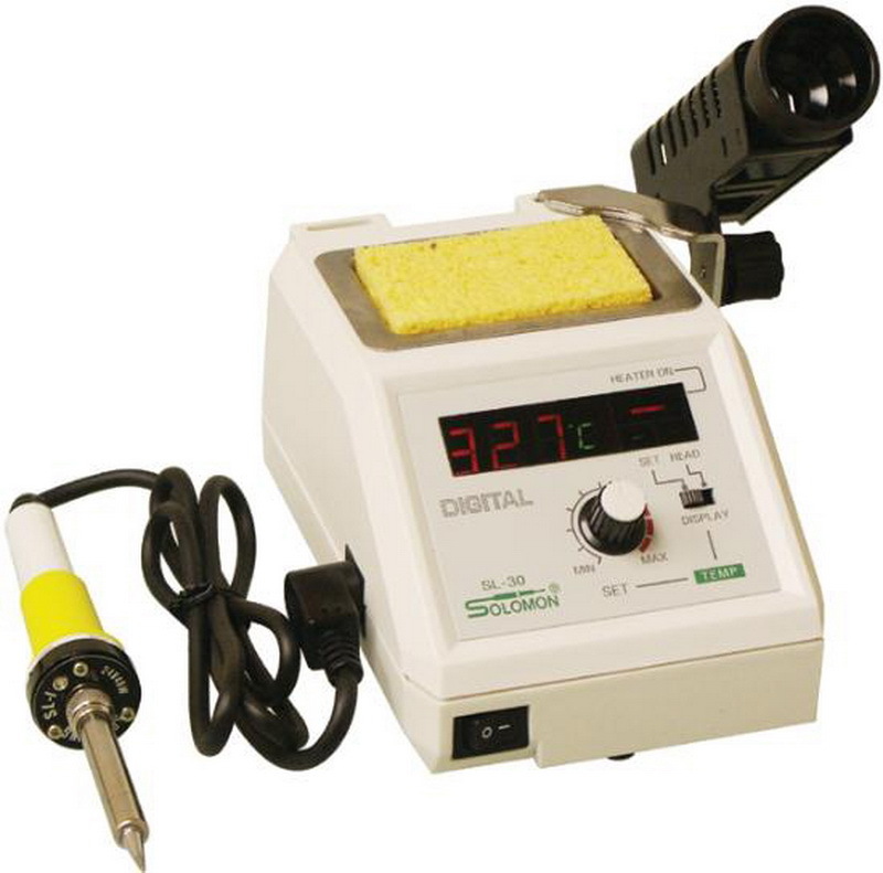
SAIKE 8858. Element 8032. Yihua 8858. ZHaoxin 858DH. , , . , , . , : (!) , , , 8. , – , , . , . , , .

Metabo BZ 12SP. . . , , . .

Velleman VTHD02. . – ( , ). - , , . , . , - . , , , 18650 . . .

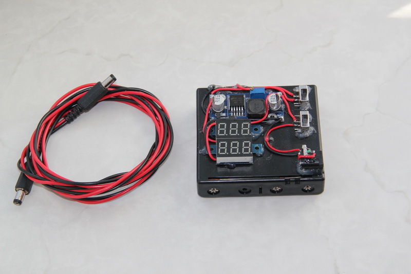
Noble NB4000P-4. . , . . – . – «» . . . – .

Fluke 179. . , , , .

-. … – ? . , , , , BOSCH GluePen. , - .
, , , ó . , . , - , -, , , , , ( - !) , ( — ), , , .
GROSS 17718. (). KBT WS-04A, 1--1.
HT-202A. ().
Solomon SL-30. . 24. . .
SAIKE 8858. Element 8032. Yihua 8858. ZHaoxin 858DH. , , . , , . , : (!) , , , 8. , – , , . , . , , .
Metabo BZ 12SP. . . , , . .
Velleman VTHD02. . – ( , ). - , , . , . , - . , , , 18650 . . .
Noble NB4000P-4. . , . . – . – «» . . . – .
Fluke 179. . , , , .
-. … – ? . , , , , BOSCH GluePen. , - .
, , , ó . , . , - , -, , , , , ( - !) , ( — ), , , .
Main components
(ebay/aliexpress) . 2016 . (- 2016 ), — .
, , , — ( ) + 4 * ( 80 + + ( ))
— 130 + +
18650 — LG 2 18650 / 2800 / 3,7V /
( — , .. 3400 !) — Panasonic NCR18650B 18650 / 3400 / 3,7V /
18650 — HX-3S-01
— 18650 Holder 3S
— Arduino Relay Module
— DC/DC Step-Down XL4005
— L298N H-bridge Motor Driver
— Arduino Nano
Arduino Nano — Arduino Nano IO Shield
bluetooth — Module Bluetooth HC-06
Polls
I don’t know how people who work can write an article in two or three days - it takes me from two to six weeks. Therefore, my performance is no more than two articles per year. It is clear that there is a rating of the article and the karma of the author, but I would like to more precisely evaluate your attitude to such material and its presentation, therefore voting in the polls below is welcome. The term of the survey - 1 year from the date of publication.
Source: https://habr.com/ru/post/397415/
All Articles