Digit Recognition on a Microcontroller
Hi, Giktayms!
UPD: There is a video demonstration .
As the name implies, this article will focus on the recognition of numbers on the microcontroller. I just want to make a reservation that this article will not provide the source code, consider the technology or the recognition algorithm, I can only say that the ideas of the systems approach are used. Some of them are presented in our articles ( here , here and here ). This is due to the fact that our approach pulls on originality, but requires clarification of some issues. Someone may say: "another article about programming microcontrollers." Far from it, the search for such projects did not give any distinct results, except for this video . From the discussions on the forums, one thing is clear: the idea of getting such a device (camera + microcontroller = recognition result at the output, and not just the picture taken) came to many, but remained without implementation. And recognition, in general opinion, requires a lot of computational resources and microcontrollers are not suitable for this, in particular, there were statements about Arduino that this is impossible at all. If it became interesting I ask under cat.
')

Whatever obvious questions arise, we will answer them:
In short, it all started with the fact that there was a desire to try your hand and test your ideas in image recognition. In the process of discussion, we came to the conclusion that we can do with small computing powers to solve this problem. For obvious reasons, we will not describe the details of these discussions.
So, the task is set, the implementation is needed. Without departing from already established principles
take what is at hand. And there was a couple of Arduino Uno on hand, an old optical mouse and a CD drive. By the way, the fact that using an optical mouse sensor as a camera to get an image was prompted by an article that was read some time ago, and the rest of the mouse material itself. The only thing we had to do was remove the sensor and its entire harness for ease of use, and also attach a lens to it, which we carefully “ripped” from the CD drive. This was necessary in order to increase the distance from the subject to the camera, otherwise the figures of our size did not fit and only a small part was visible. Incidentally, in front of the lens from the CD drive, we tried to attach the optics from the webcam, but somehow did not grow together.
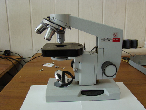
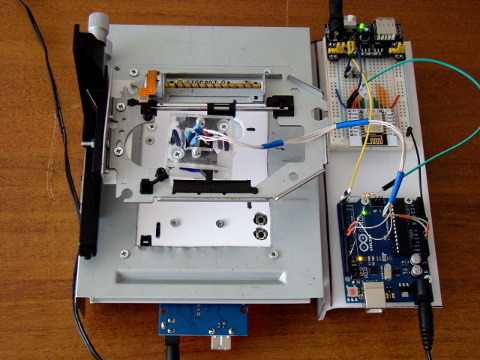
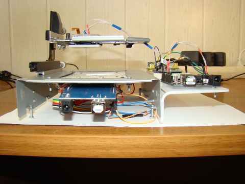
Then the question was how to position this camera above the subject. Here we were very helped by an old broken microscope, which lay idle. Yours faithfully removed from him the control mechanism of the subject table. This mechanism allowed us to move the camera along only two axes, and the thought immediately came to use the laser head guide from the CD drive. All this is fixed on the case of the long-suffering CD drive. As a result, we got a cool camera positioning mechanism.
Total: we have the so-called camera, the positioning mechanism is there, it remains to put a paper with a dial and get an image from the camera. This is where the "problems" began. Since the characteristics of the “mouse” optical sensor are very scarce for using it as a camera, they began to improvise with the backlight.
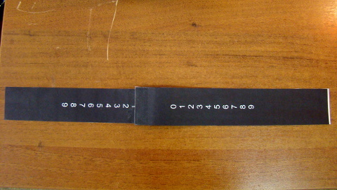
It became clear that just highlighting does not turn out important intensity, the direction of the external light also makes adjustments. It was necessary to turn on another “Arduinka” in order to control the intensity of the backlight (of course, it was possible to control it differently, but later not only on the backlight, but also switching the numbers on the indicator ). In the end, it turned out that shooting on the light is much better. And if, for example, to use a seven-segment illuminated indicator as a target, then the sensor sees it perfectly well. So, now we have an indicator and a strip with white numbers filled with a black background as objects of shooting.

on the left, the image in grayscale obtained from the indicator (such an image we get from the sensor), on the right binarized.
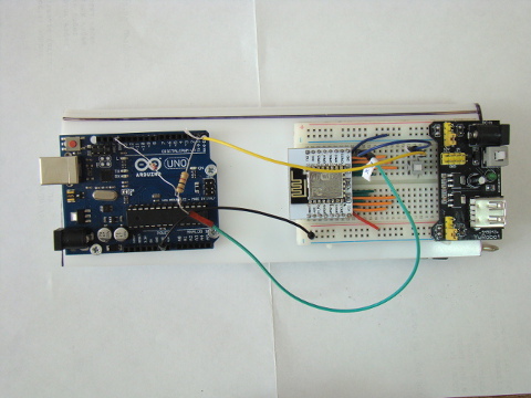
An important role in our installation is played by the so-called recognition block (in the picture above). As you can see, it consists of Arduino Uno and the well-known wifi transmitter ESP8266 . I explain, we need a wifi transmitter in order to see the recognition result on the tablet. The application on the tablet sends the request, “Arduinka”, receiving the request, “takes” the image from the mouse sensor, then binarizes it. After binarization, recognition occurs, and after it is completed, a response is formed. In response, we send the recognition result and 41 bytes to build a binarized image on the tablet screen, so to speak, for clarity.
If you look back, then the “Arduinka” has a good functionality: both working with the camera, and recognition, and working with esp8266. What could not affect the work - had to deal with the lack of memory. I never thought that I would ever have to win back every byte of memory.
This is actually all. There is still a lot of work ahead. And the first task: recognition of numbers (strings of digits) taken by a “human” camera (and not a “mouse sensor”) and transferring the developed technology to ESP8266 and reducing the heat of the struggle for each byte of memory.
We are happy to answer questions.
UPD: There is a video demonstration .
As the name implies, this article will focus on the recognition of numbers on the microcontroller. I just want to make a reservation that this article will not provide the source code, consider the technology or the recognition algorithm, I can only say that the ideas of the systems approach are used. Some of them are presented in our articles ( here , here and here ). This is due to the fact that our approach pulls on originality, but requires clarification of some issues. Someone may say: "another article about programming microcontrollers." Far from it, the search for such projects did not give any distinct results, except for this video . From the discussions on the forums, one thing is clear: the idea of getting such a device (camera + microcontroller = recognition result at the output, and not just the picture taken) came to many, but remained without implementation. And recognition, in general opinion, requires a lot of computational resources and microcontrollers are not suitable for this, in particular, there were statements about Arduino that this is impossible at all. If it became interesting I ask under cat.
')
Whatever obvious questions arise, we will answer them:
- No, this is not an image recognition service.
- No, this is not OpenCV
- No, these are not neural networks.
- Used morphological analysis of the objects of which the figure
- Yes, recognition is made by the microcontroller!
Idea
In short, it all started with the fact that there was a desire to try your hand and test your ideas in image recognition. In the process of discussion, we came to the conclusion that we can do with small computing powers to solve this problem. For obvious reasons, we will not describe the details of these discussions.
Installation
So, the task is set, the implementation is needed. Without departing from already established principles
take what is at hand. And there was a couple of Arduino Uno on hand, an old optical mouse and a CD drive. By the way, the fact that using an optical mouse sensor as a camera to get an image was prompted by an article that was read some time ago, and the rest of the mouse material itself. The only thing we had to do was remove the sensor and its entire harness for ease of use, and also attach a lens to it, which we carefully “ripped” from the CD drive. This was necessary in order to increase the distance from the subject to the camera, otherwise the figures of our size did not fit and only a small part was visible. Incidentally, in front of the lens from the CD drive, we tried to attach the optics from the webcam, but somehow did not grow together.
Still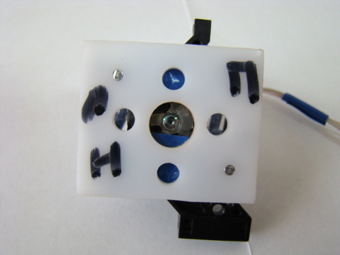
Then the question was how to position this camera above the subject. Here we were very helped by an old broken microscope, which lay idle. Yours faithfully removed from him the control mechanism of the subject table. This mechanism allowed us to move the camera along only two axes, and the thought immediately came to use the laser head guide from the CD drive. All this is fixed on the case of the long-suffering CD drive. As a result, we got a cool camera positioning mechanism.
Still


Total: we have the so-called camera, the positioning mechanism is there, it remains to put a paper with a dial and get an image from the camera. This is where the "problems" began. Since the characteristics of the “mouse” optical sensor are very scarce for using it as a camera, they began to improvise with the backlight.
Still

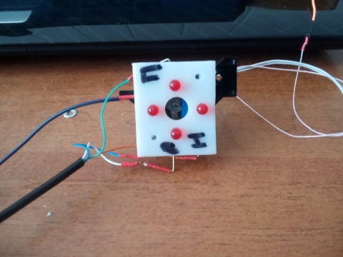
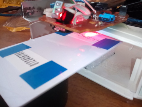
It became clear that just highlighting does not turn out important intensity, the direction of the external light also makes adjustments. It was necessary to turn on another “Arduinka” in order to control the intensity of the backlight (of course, it was possible to control it differently, but later not only on the backlight, but also switching the numbers on the indicator ). In the end, it turned out that shooting on the light is much better. And if, for example, to use a seven-segment illuminated indicator as a target, then the sensor sees it perfectly well. So, now we have an indicator and a strip with white numbers filled with a black background as objects of shooting.
on the left, the image in grayscale obtained from the indicator (such an image we get from the sensor), on the right binarized.
Still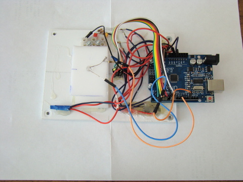
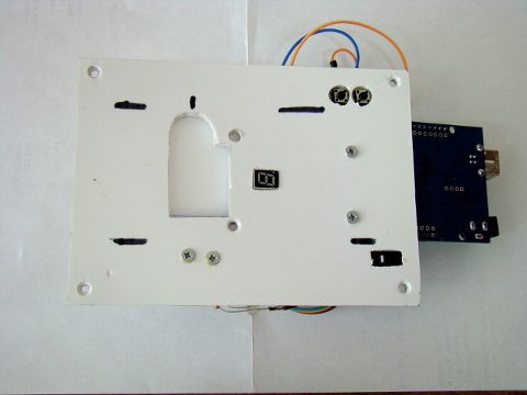
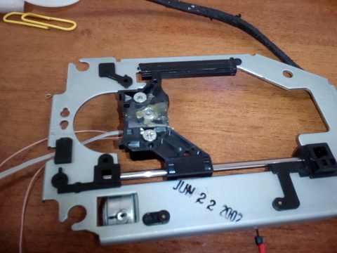
General view of the installation assembly
early installation option

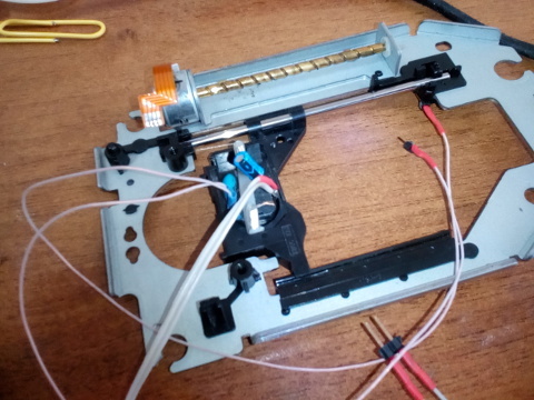
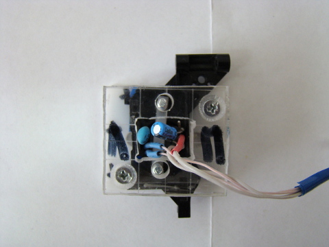
Block recognition
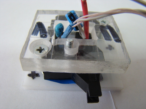
An important role in our installation is played by the so-called recognition block (in the picture above). As you can see, it consists of Arduino Uno and the well-known wifi transmitter ESP8266 . I explain, we need a wifi transmitter in order to see the recognition result on the tablet. The application on the tablet sends the request, “Arduinka”, receiving the request, “takes” the image from the mouse sensor, then binarizes it. After binarization, recognition occurs, and after it is completed, a response is formed. In response, we send the recognition result and 41 bytes to build a binarized image on the tablet screen, so to speak, for clarity.
If you look back, then the “Arduinka” has a good functionality: both working with the camera, and recognition, and working with esp8266. What could not affect the work - had to deal with the lack of memory. I never thought that I would ever have to win back every byte of memory.
Demonstration of the recognition process
Instead of conclusion
This is actually all. There is still a lot of work ahead. And the first task: recognition of numbers (strings of digits) taken by a “human” camera (and not a “mouse sensor”) and transferring the developed technology to ESP8266 and reducing the heat of the struggle for each byte of memory.
We are happy to answer questions.
Source: https://habr.com/ru/post/397193/
All Articles