Online Arduino course based on a simple starter kit
At the moment there are a large number of online and offline educational programs, courses, teaching materials on arduino and the quality of these courses comes to the fore, and it does not always meet the expectations of students and their parents. Online courses are usually ineffective due to their low interactivity. And the effectiveness of offline courses strongly depends on the qualifications of the teacher, with which sometimes there are problems due to the relative novelty of this area compared to other school subjects. This course is intended to partially solve both of these problems. On the one hand, it should be more effective than existing online courses due to a sharp increase in interactivity, which will be discussed in more detail later. On the other hand, an increase in the effectiveness of the course itself slightly reduces the role of the teacher, making it possible to use these interactive courses in regions with personnel shortages in the field of arduino teaching.
Part 1. Methodology.
So let's start with what interactivity is, why it is important and how it is achieved in this course.
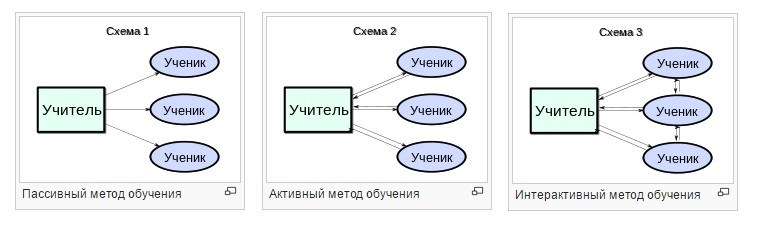
An interactive learning method involves the interaction of students not only with the teacher but also with each other. You can read more on Wikipedia.
The importance of using the interactive method lies in the fact that it is more effective than the passive teaching method. This fact is generally recognized, as is the fact that increasing interactivity increases the efficiency of the education process. More information about this can be found.
The communication between the teacher and the student, as well as between the students in the framework of this course, is implemented through the functionality of two social networks: Vkontakte and Youtube. Within both social networks, it is possible to have a public conversation, send private messages and receive alerts about the answer to your question.
Part 2. Course structure.
This course is designed for one academic year, consists of 40 lessons (one lesson per week).
In the first half of the course (20 lessons), general knowledge about the Arduino platform, its functions, capabilities is given, simple examples and the principles of its work are analyzed. It also provides examples of work with peripherals (sensors, input and output systems, actuators). It is important that for the passage of the first 20 lessons a single Arduino starter kit is enough , which can be bought at any Chinese online store, without overpaying for the brand on the package.
Each lesson of the course is based on a video lesson, contains a brief text description of the lesson, all the necessary outlines and sketches. If there are difficulties in performing the assignment, it is suggested to contact the author of the video tutorial in the comments to the video with a question, or find the right answer there if the question was raised earlier by other students. It is always possible to ask also other students who left comments on the video earlier. Youtube is better suited for this, but Vk can also be used, with the amendment that direct access to the author of the video tutorial in Vk may be limited.

In the second half of the course (classes 21 to 40), emphasis is placed on project work. Classes are also based on video lessons. At the beginning of the lesson, a list of materials, parts and equipment is given, which is necessary in addition to the Arduino starter kit. The prologue is over, go directly to the course.
Arduino Interactive Course
By combining these 20 lessons with each other, you can get another 190 (20 * 19/2) of various lessons. For example, by combining a lesson about a relay with a lesson using an IR receiver, you can assemble a device that controls the load from the TV remote control. The student in this case will have to not only connect the two elements to Arduino and write a sketch so that they work together, but also to figure out the possible purpose of such devices. Therefore, these 190 tasks can be considered creative.
Classes 21-40. Projects
At the moment, there is a search and selection of materials for classes 25-40. Links to Russian-language video tutorials with interesting projects on arduino can be left in the comments to the article.
Part 1. Methodology.
So let's start with what interactivity is, why it is important and how it is achieved in this course.
An interactive learning method involves the interaction of students not only with the teacher but also with each other. You can read more on Wikipedia.
The importance of using the interactive method lies in the fact that it is more effective than the passive teaching method. This fact is generally recognized, as is the fact that increasing interactivity increases the efficiency of the education process. More information about this can be found.
here
This video deals with several cases where an increase in interactivity increases the quality of education, and its reduction, respectively, reduces the quality of education.
')
This video gives an example of when a teacher uses the passive method of teaching, and this method is so ineffective that the teacher is offered to replace his lecture with a video.
')
This video gives an example of when a teacher uses the passive method of teaching, and this method is so ineffective that the teacher is offered to replace his lecture with a video.
The communication between the teacher and the student, as well as between the students in the framework of this course, is implemented through the functionality of two social networks: Vkontakte and Youtube. Within both social networks, it is possible to have a public conversation, send private messages and receive alerts about the answer to your question.
Why these two social networks
Because VK on attendance in Russia is ahead of everyone, and Youtube is ahead of Odnoklassniki, Facebook, Instagram and others. This allows you to fully use this course for a large audience of Russian-speaking users.

Source: TNS
Source: TNS
Part 2. Course structure.
This course is designed for one academic year, consists of 40 lessons (one lesson per week).
In the first half of the course (20 lessons), general knowledge about the Arduino platform, its functions, capabilities is given, simple examples and the principles of its work are analyzed. It also provides examples of work with peripherals (sensors, input and output systems, actuators). It is important that for the passage of the first 20 lessons a single Arduino starter kit is enough , which can be bought at any Chinese online store, without overpaying for the brand on the package.
Each lesson of the course is based on a video lesson, contains a brief text description of the lesson, all the necessary outlines and sketches. If there are difficulties in performing the assignment, it is suggested to contact the author of the video tutorial in the comments to the video with a question, or find the right answer there if the question was raised earlier by other students. It is always possible to ask also other students who left comments on the video earlier. Youtube is better suited for this, but Vk can also be used, with the amendment that direct access to the author of the video tutorial in Vk may be limited.
In the second half of the course (classes 21 to 40), emphasis is placed on project work. Classes are also based on video lessons. At the beginning of the lesson, a list of materials, parts and equipment is given, which is necessary in addition to the Arduino starter kit. The prologue is over, go directly to the course.
Arduino Interactive Course
1.Familiarity with arduino (click to expand)
Watch the first video tutorial:
You can download the development environment from the official Arduino website
Instructions for installing drivers for the Chinese Arduino here
The result should be:

The results of the passage of the task can be shared in the Vkontakte group . There you can leave a question on the instructions.
What is arduino? Opportunities and goals of the platform
The composition of the starting set Arduino
Carefully read the kit. What elements do you already know? Try to find out the functions of unfamiliar parts from a teacher or a search engine
The price can be found here . The kit usually does not have a battery, but instead you can use a power supply (sometimes power supply units from modems, routers, TV set-top boxes are suitable)


The price can be found here . The kit usually does not have a battery, but instead you can use a power supply (sometimes power supply units from modems, routers, TV set-top boxes are suitable)
Watch the first video tutorial:
You can download the development environment from the official Arduino website
Instructions for installing drivers for the Chinese Arduino here
Sketch from video tutorial
/ *
Jeremy's first program
It's awesome!
* /
int ledPin = 13;
void setup ()
{
// initialize pins as outputs
pinMode (ledPin, OUTPUT);
}
void loop ()
{
digitalWrite (ledPin, HIGH);
delay (1000);
digitalWrite (ledPin, LOW);
delay (1000);
}
Jeremy's first program
It's awesome!
* /
int ledPin = 13;
void setup ()
{
// initialize pins as outputs
pinMode (ledPin, OUTPUT);
}
void loop ()
{
digitalWrite (ledPin, HIGH);
delay (1000);
digitalWrite (ledPin, LOW);
delay (1000);
}
Standard sketch
/ *
Blink
Turn off the LED light for one second, then off for one second, repeatedly.
This example code is in the public domain.
* /
// Pin 13 has an LED connected on most Arduino boards.
// give it a name:
int led = 13;
// the setup routine runs once you press reset:
void setup () {
// initialize the digital output as an output.
pinMode (led, OUTPUT);
}
// the loop routine runs over and over again forever:
void loop () {
digitalWrite (led, HIGH); // turn the LED on (HIGH is the voltage level)
delay (1000); // wait for a second
digitalWrite (led, LOW); // turn the LED off by making the voltage LOW
delay (1000); // wait for a second
}
Also a sketch can be found here:
The result should be:
The results of the passage of the task can be shared in the Vkontakte group . There you can leave a question on the instructions.
2. Button and PWM (PWM)
The lesson describes the layout of the mock-up board, how to connect buttons and LEDs. How to determine the resistance of resistors can be found here . The effect of button rattling and the method of its elimination are also considered. Which outputs Arduino support PWM (PWM).
It should turn out like this:

On the results and questions on the passage of the lesson, you can write in the appropriate topic in the VKontakte group.
Try it yourself:
Sketch 1
/ *
Arduino tutorials
Episode 2
Switch1 Program
Written by: Jeremy Blum
* /
int switchPin = 8;
int ledPin = 13;
void setup ()
{
pinMode (switchPin, INPUT);
pinMode (ledPin, OUTPUT);
}
void loop ()
{
if (digitalRead (switchPin) == HIGH)
{
digitalWrite (ledPin, HIGH);
}
else
{
digitalWrite (ledPin, LOW);
}
}
Sketch 2
/ *
Arduino tutorials
Episode 2
Switch program
Written by: Jeremy Blum
* /
int switchPin = 8;
int ledPin = 13;
boolean lastButton = LOW;
boolean ledOn = false;
void setup ()
{
pinMode (switchPin, INPUT);
pinMode (ledPin, OUTPUT);
}
void loop ()
{
if (digitalRead (switchPin) == HIGH && lastButton == LOW)
{
ledOn =! ledOn;
lastButton = HIGH;
}
else
{
// lastButton = LOW;
lastButton = digitalRead (switchPin);
}
digitalWrite (ledPin, ledOn);
}
Sketch 3
/ *
Arduino tutorials
Episode 2
Switch3 Program (debounced)
Written by: Jeremy Blum
* /
int switchPin = 8;
int ledPin = 13;
boolean lastButton = LOW;
boolean currentButton = LOW;
boolean ledOn = false;
void setup ()
{
pinMode (switchPin, INPUT);
pinMode (ledPin, OUTPUT);
}
boolean debounce (boolean last)
{
boolean current = digitalRead (switchPin);
if (last! = current)
{
delay (5);
current = digitalRead (switchPin);
}
return current;
}
void loop ()
{
currentButton = debounce (lastButton);
if (lastButton == LOW && currentButton == HIGH)
{
ledOn =! ledOn;
}
lastButton = currentButton;
digitalWrite (ledPin, ledOn);
}
Sketch 4
/ *
Arduino tutorials
Episode 3
Switch4 Program (pwm)
Written by: Jeremy Blum
* /
int switchPin = 8;
int ledPin = 11;
boolean lastButton = LOW;
boolean currentButton = LOW;
int ledLevel = 0;
void setup ()
{
pinMode (switchPin, INPUT);
pinMode (ledPin, OUTPUT);
}
boolean debounce (boolean last)
{
boolean current = digitalRead (switchPin);
if (last! = current)
{
delay (5);
current = digitalRead (switchPin);
}
return current;
}
void loop ()
{
currentButton = debounce (lastButton);
if (lastButton == LOW && currentButton == HIGH)
{
ledLevel = ledLevel + 51;
}
lastButton = currentButton;
if (ledLevel> 255) ledLevel = 0;
analogWrite (ledPin, ledLevel);
}
It should turn out like this:
Additional videos on the topic
On the results and questions on the passage of the lesson, you can write in the appropriate topic in the VKontakte group.
Try it yourself:
3. Potentiometer. Fundamentals of circuit design
Jeremy talks about basic concepts in circuitry: current, voltage, voltage dividers, potentiometer, Ohm's law, and how it is used in practice with Arduino
At the end of the second video, a voltage stabilizer and capacitors are discussed. Separately, these parts in sets are usually not, but these parts are mounted on the Arduino board itself. Will you find these details there? In fact, Jeremy tells how the Arduino Uno power itself is arranged: no matter how much a battery or a power supply unit gives (7-14 volts), there will always be 5 volts at the output of the Arduino (in the HIGH position). The theme of the development and creation of power sources is usually not included in the Arduino courses, so the end of the second video is more introductory.
Additional task: do as shown here:
Sketch 1
// Reads the button on the screen
int buttonPin = 8;
void setup ()
{
// sets the button pin as an input
pinMode (buttonPin, INPUT);
// Allows us to listen to serial communications from the arduino
Serial.begin (9600);
}
void loop ()
{
// print the button state to a serial terminal
Serial.println (digitalRead (buttonPin));
delay (1000);
// wait one second, then print again.
}
Sketch 2
// Reads the State of the Pot
int potPin = 0;
void setup ()
{
// sets the button pin as an input
pinMode (potPin, INPUT);
// Allows us to listen to serial communications from the arduino
Serial.begin (9600);
}
void loop ()
{
// print the button state to a serial terminal
Serial.println (analogRead (potPin));
delay (1000);
// wait one second, then print again.
}
At the end of the second video, a voltage stabilizer and capacitors are discussed. Separately, these parts in sets are usually not, but these parts are mounted on the Arduino board itself. Will you find these details there? In fact, Jeremy tells how the Arduino Uno power itself is arranged: no matter how much a battery or a power supply unit gives (7-14 volts), there will always be 5 volts at the output of the Arduino (in the HIGH position). The theme of the development and creation of power sources is usually not included in the Arduino courses, so the end of the second video is more introductory.
Additional task: do as shown here:
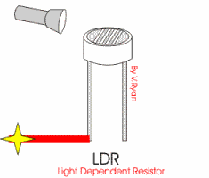
4. Light sensor
Jeremy talks about the Arduino's analog inputs, how to assemble and connect sensors to them. You will learn how to apply a photoresistor.
Connection diagram:

working principle of photoresistor:
The result should be something like this:

Ask your questions and get answers to them in the comments to the video.
Sketch here
int sensePin = 0;
int ledPin = 3;
void setup ()
{
pinMode (ledPin, OUTPUT);
}
void loop () {
int val = analogRead (sensePin);
val = constrain (val, 750, 900);
int ledLevel = map (val, 750, 900, 255, 0);
analogWrite (ledPin, ledLevel);
}
int ledPin = 3;
void setup ()
{
pinMode (ledPin, OUTPUT);
}
void loop () {
int val = analogRead (sensePin);
val = constrain (val, 750, 900);
int ledLevel = map (val, 750, 900, 255, 0);
analogWrite (ledPin, ledLevel);
}
Connection diagram:
working principle of photoresistor:
The result should be something like this:
Ask your questions and get answers to them in the comments to the video.
5. RGB LED
Scheme:

The result is:

Questions and answers as usual in the comments to the video
Sketch
const int RED_PIN = 9;
const int GREEN_PIN = 10;
const int BLUE_PIN = 11;
void setup ()
{
pinMode (RED_PIN, OUTPUT);
pinMode (GREEN_PIN, OUTPUT);
pinMode (BLUE_PIN, OUTPUT);
}
void loop ()
{
mainColors ();
showSpectrum ();
}
void mainColors ()
{
digitalWrite (RED_PIN, LOW);
digitalWrite (GREEN_PIN, LOW);
digitalWrite (BLUE_PIN, LOW);
delay (1000);
digitalWrite (RED_PIN, HIGH);
digitalWrite (GREEN_PIN, LOW);
digitalWrite (BLUE_PIN, LOW);
delay (1000);
digitalWrite (RED_PIN, LOW);
digitalWrite (GREEN_PIN, HIGH);
digitalWrite (BLUE_PIN, LOW);
delay (1000);
digitalWrite (RED_PIN, LOW);
digitalWrite (GREEN_PIN, LOW);
digitalWrite (BLUE_PIN, HIGH);
delay (1000);
digitalWrite (RED_PIN, HIGH);
digitalWrite (GREEN_PIN, HIGH);
digitalWrite (BLUE_PIN, LOW);
delay (1000);
digitalWrite (RED_PIN, LOW);
digitalWrite (GREEN_PIN, HIGH);
digitalWrite (BLUE_PIN, HIGH);
delay (1000);
digitalWrite (RED_PIN, HIGH);
digitalWrite (GREEN_PIN, LOW);
digitalWrite (BLUE_PIN, HIGH);
delay (1000);
digitalWrite (RED_PIN, HIGH);
digitalWrite (GREEN_PIN, HIGH);
digitalWrite (BLUE_PIN, HIGH);
delay (1000);
}
void showSpectrum ()
{
int x;
for (x = 0; x <768; x ++)
{
showRGB (x);
delay (10);
}
}
void showRGB (int color)
{
int redIntensity;
int greenIntensity;
int blueIntensity;
if (color <= 255)
{
redIntensity = 255 - color;
greenIntensity = color;
blueIntensity = 0;
}
else if (color <= 511)
{
redIntensity = 0;
greenIntensity = 255 - (color - 256);
blueIntensity = (color - 256);
}
else // color> = 512
{
redIntensity = (color - 512);
greenIntensity = 0;
blueIntensity = 255 - (color - 512);
}
analogWrite (RED_PIN, redIntensity);
analogWrite (BLUE_PIN, blueIntensity);
analogWrite (GREEN_PIN, greenIntensity);
}
Scheme:
The result is:
Questions and answers as usual in the comments to the video
6. Servo Library
Scheme:

The result should be something like this:
Questions and answers on the class as usual to the comments to the video
Sketch
// library with servo commands
#include <Servo.h>
// library description by reference - arduino.cc/en/Reference/Servo
Servo servo1; // Servo number 1 object
void setup ()
{
servo1.attach (9); // The servo drive is connected to digital output 9
//servo1.detach () to relax the servo motor
}
void loop ()
{
int position; // set the variable position, then it will be needed
// Twisting at full speed:
servo1.write (90); // turn 90 degrees
delay (1000); // pause for him to turn
servo1.write (180); // turn 180 degrees
delay (1000); // pause
servo1.write (0); // turn to 0 degree
delay (1000); // pause
// Twists at lower speed:
// from 0 to 180 with a bug in 2 degrees
for (position = 0; position <180; position + = 2)
{
servo1.write (position); // move to the next position
delay (20); // short break so he can move
}
// from 180 to 0 in 1 degree increments
for (position = 180; position> = 0; position - = 1)
{
servo1.write (position); // move to the next position
delay (20); // short break so he can move
}
}
Scheme:
The result should be something like this:
Questions and answers on the class as usual to the comments to the video
7. IR receiver
IRremote library
Connection diagram:

The serial monitor will display the codes for the buttons on your remote control as follows:

Questions and answers as usual in the comments to the video
Sketch
#include "IRremote.h"
// IR receiver input to A0
const int IR_PIN = A0;
// create an IR receiver object
IRrecv irrecv (IR_PIN);
void setup () {
Serial.begin (9600);
Serial.println ("ready");
// start listening to infrared signals
irrecv.enableIRIn ();
}
void loop () {
// results will be placed in the results
// decoded IR commands
decode_results results;
// If the IR command is accepted and successfully decoded -
// output the resulting code to the serial monitor
if (irrecv.decode (& results)) {
Serial.println (results.value);
irrecv.resume ();
}
}
IRremote library
Connection diagram:
The serial monitor will display the codes for the buttons on your remote control as follows:
Questions and answers as usual in the comments to the video
8. DHT11 temperature sensor
The library for the sensor is here.
Connection diagram:

The result should be:

Questions and answers on the task as usual in the comments to the video.
The library for the sensor is here.
Sketch can be taken from the library or here.
2
3
four
five
6
7
eight
9
ten
eleven
12
13
14
15
sixteen
17
18
nineteen
20
21
22
23
24
25
26
27
28
29
thirty
31
#include <DHT.h>
#define dht_apin A0 // Analog Pin sensor is connected to
dht dht;
void setup () {
Serial.begin (9600);
delay (500); // Delay to let system boot
Serial.println ("DHT11 Humidity & Temperature Sensor \ n \ n");
delay (1000); // Wait before accessing Sensor
} // end "setup ()"
void loop () {
// Start of Program
DHT.read11 (dht_apin);
Serial.print (“Current humidity =„);
Serial.print (DHT.humidity);
Serial.print (“%„);
Serial.print (“temperature =„);
Serial.print (DHT.temperature);
Serial.println (“C„);
delay (5000); // Wait 5 seconds before accessing sensor again.
// Fastest should be once every two seconds.
} // end loop ()
Connection diagram:
The result should be:
Questions and answers on the task as usual in the comments to the video.
9. LM35 temperature sensor
Wiring diagram

The result should be:

Questions and answers as usual in the comments to the video
Sketch
float tempC;
int reading;
int tempPin = 0;
void setup ()
{
analogReference (INTERNAL);
Serial.begin (9600);
}
void loop ()
{
reading = analogRead (tempPin);
tempC = reading / 9.31;
Serial.println (tempC);
delay (1000);
}
int reading;
int tempPin = 0;
void setup ()
{
analogReference (INTERNAL);
Serial.begin (9600);
}
void loop ()
{
reading = analogRead (tempPin);
tempC = reading / 9.31;
Serial.println (tempC);
delay (1000);
}
Wiring diagram
The result should be:
Questions and answers as usual in the comments to the video
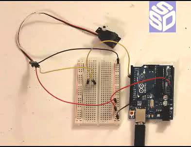
10. Relay
Connection diagram:

Relay operation principle:

Relay demonstration:

Sketch
/ *
Blink
Turn off the LED light for one second, then off for one second, repeatedly.
This example code is in the public domain.
* /
// Pin 4 has an LED connected on most Arduino boards.
// give it a name:
int led = 4;
// the setup routine runs once you press reset:
void setup () {
// initialize the digital output as an output.
pinMode (led, OUTPUT);
}
// the loop routine runs over and over again forever:
void loop () {
digitalWrite (led, HIGH); // turn the LED on (HIGH is the voltage level)
delay (1000); // wait for a second
digitalWrite (led, LOW); // turn the LED off by making the voltage LOW
delay (1000); // wait for a second
}
Connection diagram:
Relay operation principle:
Relay demonstration:
11. Seven-segment display
Connection diagram:

The result should be:

Questions and answers as usual in the comments to the video
Sketch here
//http://arduinoworks.com
int e = 3;
int d = 4;
int c = 5;
int b = 6;
int a = 7;
int f = 8;
int g = 9;
int p = 10;
void setup ()
{
pinMode (e, OUTPUT);
pinMode (d, OUTPUT);
pinMode (c, OUTPUT);
pinMode (b, OUTPUT);
pinMode (a, OUTPUT);
pinMode (f, OUTPUT);
pinMode (g, OUTPUT);
pinMode (p, OUTPUT);
digitalWrite (p, HIGH);
}
void displayDigit (int digit)
{
// Arduino Works Code for 7 segment Display
if (digit == 0)
{
digitalWrite (e, HIGH);
digitalWrite (d, HIGH);
digitalWrite (c, HIGH);
digitalWrite (b, HIGH);
digitalWrite (a, HIGH);
digitalWrite (f, HIGH);
}
else if (digit == 1)
{
digitalWrite (b, HIGH);
digitalWrite (c, HIGH);
}
else if (digit == 2)
{
digitalWrite (a, HIGH);
digitalWrite (b, HIGH);
digitalWrite (g, HIGH);
digitalWrite (e, HIGH);
digitalWrite (d, HIGH);
}
else if (digit == 3)
{
digitalWrite (a, HIGH);
digitalWrite (b, HIGH);
digitalWrite (g, HIGH);
digitalWrite (c, HIGH);
digitalWrite (d, HIGH);
}
else if (digit == 4)
{
digitalWrite (f, HIGH);
digitalWrite (g, HIGH);
digitalWrite (b, HIGH);
digitalWrite (c, HIGH);
}
else if (digit == 5)
{
digitalWrite (a, HIGH);
digitalWrite (f, HIGH);
digitalWrite (g, HIGH);
digitalWrite (c, HIGH);
digitalWrite (d, HIGH);
}
else if (digit == 6)
{
digitalWrite (a, HIGH);
digitalWrite (f, HIGH);
digitalWrite (e, HIGH);
digitalWrite (d, HIGH);
digitalWrite (c, HIGH);
digitalWrite (g, HIGH);
}
else if (digit == 7)
{
digitalWrite (a, HIGH);
digitalWrite (b, HIGH);
digitalWrite (c, HIGH);
}
else if (digit == 8)
{
digitalWrite (a, HIGH);
digitalWrite (b, HIGH);
digitalWrite (c, HIGH);
digitalWrite (d, HIGH);
digitalWrite (e, HIGH);
digitalWrite (f, HIGH);
digitalWrite (g, HIGH);
}
else if (digit == 9)
{
digitalWrite (a, HIGH);
digitalWrite (b, HIGH);
digitalWrite (c, HIGH);
digitalWrite (d, HIGH);
digitalWrite (f, HIGH);
digitalWrite (g, HIGH);
}
}
void turnOff ()
{
digitalWrite (a, LOW);
digitalWrite (b, LOW);
digitalWrite (c, LOW);
digitalWrite (d, LOW);
digitalWrite (e, LOW);
digitalWrite (f, LOW);
digitalWrite (g, LOW);
}
void loop ()
{
// 7 Segment Display with Arduino
for (int i = 0; i <10; i ++)
{
displayDigit (i);
delay (1000);
turnOff ();
}
}
Connection diagram:
The result should be:
Questions and answers as usual in the comments to the video
12. Four-digit seven-segment indicator
Connection diagram:

Segment designations on the display

The result will be similar to this:

In practice, this display is used very rarely, since it takes almost all the outputs of the Arduino. It is more convenient to use a similar display, occupying only 4 pins on arduino:

Questions and answers in the comments to the video.
Sketch here
/ * Declare the variables A, B, C, D, E, F, G and DP.
And put there the values from 5 to 12: these will be the outputs of the Arduino Uno,
with the help of which we will manage the segments. * /
int A = 5;
int B = 6;
int C = 7;
int D = 8;
int E = 9;
int F = 10;
int G = 11;
int DP = 12;
int z, y, w, x;
int K1 = 4;
int K2 = 3;
int K3 = 2;
int K4 = 1;
/ * Declare arrays for each indicator segment
in which we will store its state for each of the numbers,
from 0 to 9. * /
int a [10] = {1,0,1,1,0,1,1,1,1,1};
int b [10] = {1,1,1,1,1,0,0,1,1,1};
int c [10] = {1,1,0,1,1,1,1,1,1,1};
int d [10] = {1,0,1,1,0,1,1,0,1,1};
int e [10] = {1,0,1,0,0,0,1,0,1,0};
int f [10] = {1,0,0,0,1,1,1,0,1,1};
int g [10] = {0,0,1,1,1,1,1,1,1,1};
int dp [10] = {0,0,0,0,0,0,0,0,0,0,0};
void setup () {
// Assign the Arduino pins we need
pinMode (A, OUTPUT);
pinMode (B, OUTPUT);
pinMode (C, OUTPUT);
pinMode (D, OUTPUT);
pinMode (E, OUTPUT);
pinMode (F, OUTPUT);
pinMode (G, OUTPUT);
pinMode (DP, OUTPUT);
pinMode (K1, OUTPUT);
pinMode (K2, OUTPUT);
pinMode (K3, OUTPUT);
pinMode (K4, OUTPUT);
}
void loop () {
for (z = 9; z> 1; z-) {
for (y = 9; y> 1; y-) {
for (w = 9; w> 1; w-) {
for (x = 9; x> 1; x-) {
Myflesh (z, y, w, x);
Myflesh (z, y, w, x);
Myflesh (z, y, w, x);
Myflesh (z, y, w, x);
Myflesh (z, y, w, x);
}
}
}
}
}
void Myflesh (int i, int j, int k, int m) {
digitalWrite (A, a [i]);
digitalWrite (B, b [i]);
digitalWrite (C, c [i]);
digitalWrite (D, d [i]);
digitalWrite (E, e [i]);
digitalWrite (F, f [i]);
digitalWrite (G, g [i]);
digitalWrite (DP, dp [i]);
digitalWrite (K1, 0);
delay (3);
digitalWrite (K1, 1);
digitalWrite (A, a [j]);
digitalWrite (B, b [j]);
digitalWrite (C, c [j]);
digitalWrite (D, d [j]);
digitalWrite (E, e [j]);
digitalWrite (F, f [j]);
digitalWrite (G, g [j]);
digitalWrite (DP, dp [j]);
digitalWrite (K2, 0);
delay (3);
digitalWrite (K2, 1);
digitalWrite (A, a [k]);
digitalWrite (B, b [k]);
digitalWrite (C, c [k]);
digitalWrite (D, d [k]);
digitalWrite (E, e [k]);
digitalWrite (F, f [k]);
digitalWrite (G, g [k]);
digitalWrite (DP, dp [k]);
digitalWrite (K3, 0);
delay (3);
digitalWrite (K3, 1);
digitalWrite (A, a [m]);
digitalWrite (B, b [m]);
digitalWrite (C, c [m]);
digitalWrite (D, d [m]);
digitalWrite (E, e [m]);
digitalWrite (F, f [m]);
digitalWrite (G, g [m]);
digitalWrite (DP, dp [m]);
digitalWrite (K4, 0);
delay (3);
digitalWrite (K4, 1);
// delay (3);
}
Sketch to the scheme below
/ *
This Arduino code for “4-digit-7-segment-led-display” (KYX-5461AS).
* This code can display one Number in all 4 digit!
* This code can display 4
* This code can also make a Number Countdown (Timers).
author: Oussama Amri (@amriunix)
website: ithepro.com
* /
// display pins
int segA = 5; // >> 11
int segB = 13; // >> 7
int segC = 10; // >> 4
int segD = 8; // >> 2
int segE = 7; // >> 1
int segF = 4; // >> 10
int segG = 11; // >> 5
int segPt = 9; // >> 3
// ------------ //
// display digit
int d1 = 6; // >> 12
int d2 = 3; // >> 9
int d3 = 2; // >> 8
int d4 = 12; // >> 6
// ------------ //
int delayTime = 5000; // delayTime
int i = 0;
// ============================================= //
// init all pin used
void setup () {
pinMode (2, OUTPUT);
pinMode (3, OUTPUT);
pinMode (4, OUTPUT);
pinMode (5, OUTPUT);
pinMode (6, OUTPUT);
pinMode (7, OUTPUT);
pinMode (8, OUTPUT);
pinMode (9, OUTPUT);
pinMode (10, OUTPUT);
pinMode (11, OUTPUT);
pinMode (12, OUTPUT);
pinMode (13, OUTPUT);
}
// ============================================= //
void loop () {
// down (0,0,2,4);
all (5);
// writeN (1,9,9,4);
}
// ============================================= //
// Write a Number - writeN (1,9,9,0) -> 1990
void writeN (int a, int b, int c, int d) {
selectDwriteL (1, a);
selectDwriteL (2, b);
selectDwriteL (3, c);
selectDwriteL (4, d);
}
// ============================================= //
// Make a Number Number Countdown (Timers).
void down (int a, int b, int c, int d) {
while (a! = -1) {
while (b! = -1) {
while (c! = -1) {
while (d! = -1) {
while (i <10) {// i here is like a timer! because we can't use delay function
selectDwriteL (1, a);
selectDwriteL (2, b);
selectDwriteL (3, c);
selectDwriteL (4, d);
i ++;
}
i = 0;
d--;
}
d = 9;
c--;
}
c = 9;
b--;
}
b = 9;
a--;
}
}
// ============================================= //
// Select Wich Digit (selectD) is going to Display (writeL)
void selectDwriteL (int d, int l) {
switch (d) {// choose a digit
case 0: digitalWrite (d1, LOW); // case 0 - All ON
digitalWrite (d2, LOW);
digitalWrite (d3, LOW);
digitalWrite (d4, LOW);
break;
case 1: digitalWrite (d1, LOW); // case 1 - Digit Number 1
digitalWrite (d2, HIGH);
digitalWrite (d3, HIGH);
digitalWrite (d4, HIGH);
break;
case 2: digitalWrite (d1, HIGH); // case 1 - Digit Number 2
digitalWrite (d2, LOW);
digitalWrite (d3, HIGH);
digitalWrite (d4, HIGH);
break;
case 3: digitalWrite (d1, HIGH); // case 1 - Digit Number 3
digitalWrite (d2, HIGH);
digitalWrite (d3, LOW);
digitalWrite (d4, HIGH);
break;
case 4: digitalWrite (d1, HIGH); // case 1 - Digit Number 4
digitalWrite (d2, HIGH);
digitalWrite (d3, HIGH);
digitalWrite (d4, LOW);
break;
}
switch (l) {// choose a Number
case 0: zero ();
break;
case 1: one ();
break;
case 2: two ();
break;
case 3: three ();
break;
case 4: four ();
break;
case 5: five ();
break;
case 6: six ();
break;
case 7: seven ();
break;
case 8: eight ();
break;
case 9: nine ();
break;
case 10: point (); // print a Point
break;
case 11: none (); // make all them off!
break;
}
delayMicroseconds (delayTime); // delayTime for nice display of the Number!
}
// ============================================= //
// shown one Number in the 4 Digit
void all (int n) {
selectDwriteL (0, n);
}
// ============================================= //
void zero () {
digitalWrite (segA, HIGH);
digitalWrite (segB, HIGH);
digitalWrite (segC, HIGH);
digitalWrite (segD, HIGH);
digitalWrite (segE, HIGH);
digitalWrite (segF, HIGH);
digitalWrite (segG, LOW);
digitalWrite (segPt, LOW);
}
// ============================================= //
void one () {
digitalWrite (segA, LOW);
digitalWrite (segB, HIGH);
digitalWrite (segC, HIGH);
digitalWrite (segD, LOW);
digitalWrite (segE, LOW);
digitalWrite (segF, LOW);
digitalWrite (segG, LOW);
digitalWrite (segPt, LOW);
}
// ============================================= //
void two () {
digitalWrite (segA, HIGH);
digitalWrite (segB, HIGH);
digitalWrite (segC, LOW);
digitalWrite (segD, HIGH);
digitalWrite (segE, HIGH);
digitalWrite (segF, LOW);
digitalWrite (segG, HIGH);
digitalWrite (segPt, LOW);
}
// ============================================= //
void three () {
digitalWrite (segA, HIGH);
digitalWrite (segB, HIGH);
digitalWrite (segC, HIGH);
digitalWrite (segD, HIGH);
digitalWrite (segE, LOW);
digitalWrite (segF, LOW);
digitalWrite (segG, HIGH);
digitalWrite (segPt, LOW);
}
// ============================================= //
void four () {
digitalWrite (segA, LOW);
digitalWrite (segB, HIGH);
digitalWrite (segC, HIGH);
digitalWrite (segD, LOW);
digitalWrite (segE, LOW);
digitalWrite (segF, HIGH);
digitalWrite (segG, HIGH);
digitalWrite (segPt, LOW);
}
// ============================================= //
void five () {
digitalWrite (segA, HIGH);
digitalWrite (segB, LOW);
digitalWrite (segC, HIGH);
digitalWrite (segD, HIGH);
digitalWrite (segE, LOW);
digitalWrite (segF, HIGH);
digitalWrite (segG, HIGH);
digitalWrite (segPt, LOW);
}
// ============================================= //
void six () {
digitalWrite (segA, HIGH);
digitalWrite (segB, LOW);
digitalWrite (segC, HIGH);
digitalWrite (segD, HIGH);
digitalWrite (segE, HIGH);
digitalWrite (segF, HIGH);
digitalWrite (segG, HIGH);
digitalWrite (segPt, LOW);
}
// ============================================= //
void seven () {
digitalWrite (segA, HIGH);
digitalWrite (segB, HIGH);
digitalWrite (segC, HIGH);
digitalWrite (segD, LOW);
digitalWrite (segE, LOW);
digitalWrite (segF, LOW);
digitalWrite (segG, LOW);
digitalWrite (segPt, LOW);
}
// ============================================= //
void eight () {
digitalWrite (segA, HIGH);
digitalWrite (segB, HIGH);
digitalWrite (segC, HIGH);
digitalWrite (segD, HIGH);
digitalWrite (segE, HIGH);
digitalWrite (segF, HIGH);
digitalWrite (segG, HIGH);
digitalWrite (segPt, LOW);
}
// ============================================= //
void nine () {
digitalWrite (segA, HIGH);
digitalWrite (segB, HIGH);
digitalWrite (segC, HIGH);
digitalWrite (segD, HIGH);
digitalWrite (segE, LOW);
digitalWrite (segF, HIGH);
digitalWrite (segG, HIGH);
digitalWrite (segPt, LOW);
}
// ============================================= //
void point () {
digitalWrite (segA, LOW);
digitalWrite (segB, LOW);
digitalWrite (segC, LOW);
digitalWrite (segD, LOW);
digitalWrite (segE, LOW);
digitalWrite (segF, LOW);
digitalWrite (segG, LOW);
digitalWrite (segPt, HIGH);
}
// ============================================= //
void none () {
digitalWrite (segA, LOW);
digitalWrite (segB, LOW);
digitalWrite (segC, LOW);
digitalWrite (segD, LOW);
digitalWrite (segE, LOW);
digitalWrite (segF, LOW);
digitalWrite (segG, LOW);
digitalWrite (segPt, LOW);
}
Connection diagram:
Segment designations on the display
The result will be similar to this:
In practice, this display is used very rarely, since it takes almost all the outputs of the Arduino. It is more convenient to use a similar display, occupying only 4 pins on arduino:
Questions and answers in the comments to the video.
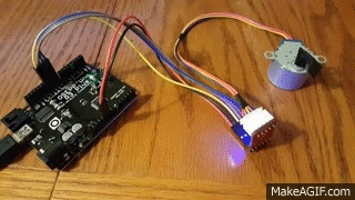
13. Stepper motor 28BYJ-48
Connection diagram:
5V+ connect to +5V
5V- connect to 0V (Ground)
IN1: to Arduino digital input pin 8
IN2: to Arduino digital input pin 9
IN3: to Arduino digital input pin 10
IN4: to Arduino digital input pin 11
:
.
Sketch here
// This Arduino example demonstrates bidirectional operation of a
// 28BYJ-48, using a ULN2003 interface board to drive the stepper.
// The 28BYJ-48 motor is a 4-phase, 8-beat motor, geared down by
// a factor of 68. One bipolar winding is on motor pins 1 & 3 and
// the other on motor pins 2 & 4. The step angle is 5.625 / 64 and the
// operating Frequency is 100pps. Current draw is 92mA.
////////////////////////////////////////////////
// declare variables for the motor pins
int motorPin1 = 8; // Blue - 28BYJ48 pin 1
int motorPin2 = 9; // Pink - 28BYJ48 pin 2
int motorPin3 = 10; // Yellow - 28BYJ48 pin 3
int motorPin4 = 11; // Orange - 28BYJ48 pin 4
// Red - 28BYJ48 pin 5 (VCC)
int motorSpeed = 1200; // variable to set stepper speed
int count = 0; // count of steps made
int countsperrev = 512; // number of steps per full revolution
int lookup [8] = {B01000, B01100, B00100, B00110, B00010, B00011, B00001, B01001};
////////////////////////////////////////////////// ////////////////////////////
void setup () {
// declare the motor pins as outputs
pinMode (motorPin1, OUTPUT);
pinMode(motorPin2, OUTPUT);
pinMode(motorPin3, OUTPUT);
pinMode(motorPin4, OUTPUT);
Serial.begin (9600);
}
//////////////////////////////////////////////////////////////////////////////
void loop(){
if(count < countsperrev )
clockwise();
else if (count == countsperrev * 2)
count = 0;
else
anticlockwise();
count++;
}
//////////////////////////////////////////////////////////////////////////////
//set pins to ULN2003 high in sequence from 1 to 4
//delay «motorSpeed» between each pin setting (to determine speed)
void anticlockwise()
{
for(int i = 0; i < 8; i++)
{
setOutput(i);
delayMicroseconds(motorSpeed);
}
}
void clockwise()
{
for(int i = 7; i >= 0; i--)
{
setOutput(i);
delayMicroseconds(motorSpeed);
}
}
void setOutput(int out)
{
digitalWrite(motorPin1, bitRead(lookup[out], 0));
digitalWrite(motorPin2, bitRead(lookup[out], 1));
digitalWrite(motorPin3, bitRead(lookup[out], 2));
digitalWrite(motorPin4, bitRead(lookup[out], 3));
}
Connection diagram:
5V+ connect to +5V
5V- connect to 0V (Ground)
IN1: to Arduino digital input pin 8
IN2: to Arduino digital input pin 9
IN3: to Arduino digital input pin 10
IN4: to Arduino digital input pin 11
:
.
14. Joystick
Connection diagram:

:
.
/*
AnalogReadSerial
Reads an analog input on pin 0, prints the result to the serial monitor.
Attach the center pin of a potentiometer to pin A0, and the outside pins to +5V and ground.
This example code is in the public domain.
*/
// the setup routine runs once when you press reset:
void setup() {
// initialize serial communication at 9600 bits per second:
Serial.begin (9600);
}
// the loop routine runs over and over again forever:
void loop() {
// read the input on analog pin 0:
int sensorValue = analogRead(A0);
// print out the value you read:
Serial.println(sensorValue);
delay (1); // delay in between reads for stability
}
// Controlling a servo position using a potentiometer (variable resistor)
// by Michal Rinott < people.interaction-ivrea.it/m.rinott >
#include <Servo.h>
Servo myservo; // create servo object to control a servo
int potpin = 0; // analog pin used to connect the potentiometer
int val; // variable to read the value from the analog pin
void setup()
{
myservo.attach(9); // attaches the servo on pin 9 to the servo object
}
void loop()
{
val = analogRead(potpin); // reads the value of the potentiometer (value between 0 and 1023)
val = map(val, 0, 1023, 0, 179); // scale it to use it with the servo (value between 0 and 180)
myservo.write(val); // sets the servo position according to the scaled value
delay(15); // waits for the servo to get there
}
Connection diagram:
:
.
15. Sound sensor
Connection diagram:

, .
:

:

.
/*
AnalogReadSerial
Reads an analog input on pin 0, prints the result to the serial monitor.
Attach the center pin of a potentiometer to pin A0, and the outside pins to +5V and ground.
This example code is in the public domain.
*/
// the setup routine runs once when you press reset:
void setup() {
// initialize serial communication at 9600 bits per second:
Serial.begin (9600);
}
// the loop routine runs over and over again forever:
void loop() {
// read the input on analog pin 0:
int sensorValue = analogRead(A0);
// print out the value you read:
Serial.println(sensorValue);
delay (1); // delay in between reads for stability
}
AnalogReadSerial
Reads an analog input on pin 0, prints the result to the serial monitor.
Attach the center pin of a potentiometer to pin A0, and the outside pins to +5V and ground.
This example code is in the public domain.
*/
// the setup routine runs once when you press reset:
void setup() {
// initialize serial communication at 9600 bits per second:
Serial.begin (9600);
}
// the loop routine runs over and over again forever:
void loop() {
// read the input on analog pin 0:
int sensorValue = analogRead(A0);
// print out the value you read:
Serial.println(sensorValue);
delay (1); // delay in between reads for stability
}
Connection diagram:
, .
:
int Count=0; //
int Relay=0; //
void setup() {
pinMode(3, OUTPUT); // 3
}
void loop() {
Count=analogRead(4); //
if(Count > 200 && Count < 600)
{
delay(250); // 250
for(int t=0; t<=500; t++)
{
delay (1);
Count=analogRead(4); //
if(Count > 200 && Count < 600)
{
Relay=!Relay; //
break; //
delay(200); //
}
}
}
digitalWrite(3,Relay);
}
:
:
.
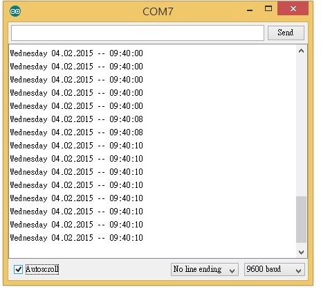
16. DS1302 clock module
Connection diagram:

:
// DS1302_Serial_Easy ©2010 Henning Karlsen
// web: www.henningkarlsen.com/electronics
//
// A quick demo of how to use my DS1302-library to
// quickly send time and date information over a serial link
//
// I assume you know how to connect the DS1302.
// DS1302: CE pin -> Arduino Digital 2
// I/O pin -> Arduino Digital 3
// SCLK pin -> Arduino Digital 4
#include <DS1302.h>
// Init the DS1302
DS1302 rtc(2, 3, 4);
void setup()
{
// Set the clock to run-mode, and disable the write protection
rtc.halt(false);
rtc.writeProtect(false);
// Setup Serial connection
Serial.begin (9600);
// The following lines can be commented out to use the values already stored in the DS1302
rtc.setDOW(FRIDAY); // Set Day-of-Week to FRIDAY
rtc.setTime(12, 0, 0); // Set the time to 12:00:00 (24hr format)
rtc.setDate(6, 8, 2010); // Set the date to August 6th, 2010
}
void loop()
{
// Send Day-of-Week
Serial.print(rtc.getDOWStr());
Serial.print(" ");
// Send date
Serial.print(rtc.getDateStr());
Serial.print(" — ");
// Send time
Serial.println(rtc.getTimeStr());
// Wait one second before repeating :)
delay (1000);
}
Connection diagram:
:
17. Liquid level sensor
:
:
: dc3-5v
: 20
:
. . lang
Connection diagram:

:

:
: dc3-5v
: 20
:
. . lang
AnalogRead
/*
AnalogReadSerial
Reads an analog input on pin 0, prints the result to the serial monitor.
Attach the center pin of a potentiometer to pin A0, and the outside pins to +5V and ground.
This example code is in the public domain.
*/
// the setup routine runs once when you press reset:
void setup() {
// initialize serial communication at 9600 bits per second:
Serial.begin (9600);
}
// the loop routine runs over and over again forever:
void loop() {
// read the input on analog pin 0:
int sensorValue = analogRead(A0);
// print out the value you read:
Serial.println(sensorValue);
delay (1); // delay in between reads for stability
}
AnalogReadSerial
Reads an analog input on pin 0, prints the result to the serial monitor.
Attach the center pin of a potentiometer to pin A0, and the outside pins to +5V and ground.
This example code is in the public domain.
*/
// the setup routine runs once when you press reset:
void setup() {
// initialize serial communication at 9600 bits per second:
Serial.begin (9600);
}
// the loop routine runs over and over again forever:
void loop() {
// read the input on analog pin 0:
int sensorValue = analogRead(A0);
// print out the value you read:
Serial.println(sensorValue);
delay (1); // delay in between reads for stability
}
Connection diagram:
:
18. Matrix 8x8
. 16 . MAX7219, 5 .

Connection diagram:

:
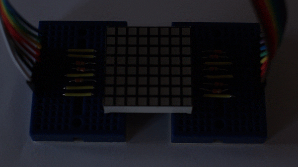
// Show messages scrolling from right to left.
#include <FrequencyTimer2.h>
#define SPACE { \
{0, 0, 0, 0, 0, 0, 0, 0}, \
{0, 0, 0, 0, 0, 0, 0, 0}, \
{0, 0, 0, 0, 0, 0, 0, 0}, \
{0, 0, 0, 0, 0, 0, 0, 0}, \
{0, 0, 0, 0, 0, 0, 0, 0}, \
{0, 0, 0, 0, 0, 0, 0, 0}, \
{0, 0, 0, 0, 0, 0, 0, 0}, \
{0, 0, 0, 0, 0, 0, 0, 0} \
}
#define E { \
{0, 1, 1, 1, 1, 1, 1, 0}, \
{0, 1, 0, 0, 0, 0, 0, 0}, \
{0, 1, 0, 0, 0, 0, 0, 0}, \
{0, 1, 1, 1, 1, 1, 1, 0}, \
{0, 1, 0, 0, 0, 0, 0, 0}, \
{0, 1, 0, 0, 0, 0, 0, 0}, \
{0, 1, 0, 0, 0, 0, 0, 0}, \
{0, 1, 1, 1, 1, 1, 1, 0} \
}
#define G { \
{0, 1, 1, 1, 1, 1, 1, 0}, \
{0, 1, 0, 0, 0, 0, 0, 0}, \
{0, 1, 0, 0, 0, 0, 0, 0}, \
{0, 1, 0, 0, 0, 1, 1, 1}, \
{0, 1, 0, 0, 0, 0, 1, 0}, \
{0, 1, 0, 0, 0, 0, 1, 0}, \
{0, 1, 0, 0, 0, 0, 1, 0}, \
{0, 1, 1, 1, 1, 1, 1, 0} \
}
#define H { \
{0, 1, 0, 0, 0, 0, 1, 0}, \
{0, 1, 0, 0, 0, 0, 1, 0}, \
{0, 1, 0, 0, 0, 0, 1, 0}, \
{0, 1, 1, 1, 1, 1, 1, 0}, \
{0, 1, 0, 0, 0, 0, 1, 0}, \
{0, 1, 0, 0, 0, 0, 1, 0}, \
{0, 1, 0, 0, 0, 0, 1, 0}, \
{0, 1, 0, 0, 0, 0, 1, 0} \
}
#define K { \
{0, 1, 0, 0, 0, 0, 1, 0}, \
{0, 1, 0, 0, 0, 1, 0, 0}, \
{0, 1, 0, 0, 1, 0, 0, 0}, \
{0, 1, 1, 1, 0, 0, 0, 0}, \
{0, 1, 0, 1, 0, 0, 0, 0}, \
{0, 1, 0, 0, 1, 0, 0, 0}, \
{0, 1, 0, 0, 0, 1, 0, 0}, \
{0, 1, 0, 0, 0, 0, 1, 0} \
}
#define L { \
{0, 1, 0, 0, 0, 0, 0, 0}, \
{0, 1, 0, 0, 0, 0, 0, 0}, \
{0, 1, 0, 0, 0, 0, 0, 0}, \
{0, 1, 0, 0, 0, 0, 0, 0}, \
{0, 1, 0, 0, 0, 0, 0, 0}, \
{0, 1, 0, 0, 0, 0, 0, 0}, \
{0, 1, 0, 0, 0, 0, 0, 0}, \
{0, 1, 1, 1, 1, 1, 1, 0} \
}
#define O { \
{0, 0, 0, 1, 1, 0, 0, 0}, \
{0, 0, 1, 0, 0, 1, 0, 0}, \
{0, 1, 0, 0, 0, 0, 1, 0}, \
{0, 1, 0, 0, 0, 0, 1, 0}, \
{0, 1, 0, 0, 0, 0, 1, 0}, \
{0, 1, 0, 0, 0, 0, 1, 0}, \
{0, 0, 1, 0, 0, 1, 0, 0}, \
{0, 0, 0, 1, 1, 0, 0, 0} \
}
byte col=0;
byte leds[8][8];
int pins[17]={-1, 5, 4, 3, 2, 14, 15, 16, 17, 13, 12, 11, 10, 9, 8, 7, 6};
int cols[8] ={pins[13], pins[3], pins[4], pins[10], pins[06], pins[11], pins[15], pins[16]};
int rows[8] ={pins[9], pins[14], pins[8], pins[12], pins[1], pins[7], pins[2], pins[5]};
const int numPatterns=10;
byte patterns[numPatterns][8][8]={H,E,L,L,O,SPACE,G,K,L,SPACE};
int pattern=0;
void setup()
{
for (int i=1; i<=16; i++) {pinMode(pins[i], OUTPUT);}
for (int i=1; i<=8; i++) {digitalWrite(cols[i-1], LOW);}
for (int i=1; i<=8; i++) {digitalWrite(rows[i-1], LOW);}
clearLeds();
FrequencyTimer2::disable();
FrequencyTimer2::setPeriod(2000); // sets refresh rate
FrequencyTimer2::setOnOverflow(display);
setPattern(pattern);
}
void loop()
{
pattern=++pattern%numPatterns;
slidePattern(pattern, 60);
}
void clearLeds() {
for (int i=0; i<8; i++) {
for (int j=0; j<8; j++) {leds[i][j]=0;}
}
}
void setPattern(int pattern) {
for (int i=0; i<8; i++) {
for (int j=0; j<8; j++) {leds[i][j] = patterns[pattern][i][j];}
}
}
void slidePattern(int pattern, int del) {
for (int l=0; l<8; l++) {
for (int i=0; i<7; i++) {
for (int j=0; j<8; j++) {leds[j][i] = leds[j][i+1];}
}
for (int j=0; j<8; j++) {leds[j][7] = patterns[pattern][j][0 + l];}
delay(del);
}
}
void display() {
digitalWrite(cols[col], LOW);
col++;
if (col==8) {col=0;}
for (int row=0; row<8; row++) {
if (leds[col][7-row]==1) {digitalWrite(rows[row], LOW);}
else {digitalWrite(rows[row], HIGH);}
}
digitalWrite(cols[col], HIGH);}
Connection diagram:
:
19. RC522 RFID Reader
Connection diagram:

:

.
Dumpinfo
/*
* — * Example sketch/program showing how to read data from a PICC to serial.
* — * This is a MFRC522 library example; for further details and other examples see: github.com/miguelbalboa/rfid
*
* Example sketch/program showing how to read data from a PICC (that is: a RFID Tag or Card) using a MFRC522 based RFID
* Reader on the Arduino SPI interface.
*
* When the Arduino and the MFRC522 module are connected (see the pin layout below), load this sketch into Arduino IDE
* then verify/compile and upload it. To see the output: use Tools, Serial Monitor of the IDE (hit Ctrl+Shft+M). When
* you present a PICC (that is: a RFID Tag or Card) at reading distance of the MFRC522 Reader/PCD, the serial output
* will show the ID/UID, type and any data blocks it can read. Note: you may see «Timeout in communication» messages
* when removing the PICC from reading distance too early.
*
* If your reader supports it, this sketch/program will read all the PICCs presented (that is: multiple tag reading).
* So if you stack two or more PICCs on top of each other and present them to the reader, it will first output all
* details of the first and then the next PICC. Note that this may take some time as all data blocks are dumped, so
* keep the PICCs at reading distance until complete.
*
* @license Released into the public domain.
*
* Typical pin layout used:
* — * MFRC522 Arduino Arduino Arduino Arduino Arduino
* Reader/PCD Uno Mega Nano v3 Leonardo/Micro Pro Micro
* Signal Pin Pin Pin Pin Pin Pin
* — * RST/Reset RST 9 5 D9 RESET/ICSP-5 RST
* SPI SS SDA(SS) 10 53 D10 10 10
* SPI MOSI MOSI 11 / ICSP-4 51 D11 ICSP-4 16
* SPI MISO MISO 12 / ICSP-1 50 D12 ICSP-1 14
* SPI SCK SCK 13 / ICSP-3 52 D13 ICSP-3 15
*/
#include <SPI.h>
#include <MFRC522.h>
#define RST_PIN 9 // Configurable, see typical pin layout above
#define SS_PIN 10 // Configurable, see typical pin layout above
MFRC522 mfrc522(SS_PIN, RST_PIN); // Create MFRC522 instance
void setup() {
Serial.begin (9600); // Initialize serial communications with the PC
while (!Serial); // Do nothing if no serial port is opened (added for Arduinos based on ATMEGA32U4)
SPI.begin(); // Init SPI bus
mfrc522.PCD_Init(); // Init MFRC522
mfrc522.PCD_DumpVersionToSerial(); // Show details of PCD — MFRC522 Card Reader details
Serial.println(F(«Scan PICC to see UID, SAK, type, and data blocks...»));
}
void loop() {
// Look for new cards
if (! mfrc522.PICC_IsNewCardPresent()) {
return;
}
// Select one of the cards
if (! mfrc522.PICC_ReadCardSerial()) {
return;
}
// Dump debug info about the card; PICC_HaltA() is automatically called
mfrc522.PICC_DumpToSerial(&(mfrc522.uid));
}
Connection diagram:
:
.
20. 16x2 display
LiquidCrystal_I2C
Connection diagram:

:
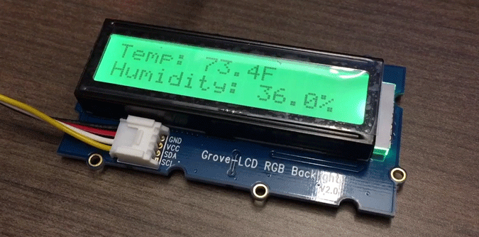
LiquidCrystal_I2C
I2C Scanner
// — // i2c_scanner
//
// Version 1
// This program (or code that looks like it)
// can be found in many places.
// For example on the Arduino.cc forum.
// The original author is not know.
// Version 2, Juni 2012, Using Arduino 1.0.1
// Adapted to be as simple as possible by Arduino.cc user Krodal
// Version 3, Feb 26 2013
// V3 by louarnold
// Version 4, March 3, 2013, Using Arduino 1.0.3
// by Arduino.cc user Krodal.
// Changes by louarnold removed.
// Scanning addresses changed from 0...127 to 1...119,
// according to the i2c scanner by Nick Gammon
// www.gammon.com.au/forum/?id=10896
// Version 5, March 28, 2013
// As version 4, but address scans now to 127.
// A sensor seems to use address 120.
// Version 6, November 27, 2015.
// Added waiting for the Leonardo serial communication.
//
//
// This sketch tests the standard 7-bit addresses
// Devices with higher bit address might not be seen properly.
//
#include <Wire.h>
void setup()
{
Wire.begin();
Serial.begin (9600);
while (!Serial); // Leonardo: wait for serial monitor
Serial.println("\nI2C Scanner");
}
void loop()
{
byte error, address;
int nDevices;
Serial.println(«Scanning...»);
nDevices = 0;
for(address = 1; address < 127; address++ )
{
// The i2c_scanner uses the return value of
// the Write.endTransmisstion to see if
// a device did acknowledge to the address.
Wire.beginTransmission(address);
error = Wire.endTransmission();
if (error == 0)
{
Serial.print(«I2C device found at address 0x»);
if (address<16)
Serial.print(«0»);
Serial.print(address,HEX);
Serial.println(" !");
nDevices++;
}
else if (error==4)
{
Serial.print(«Unknow error at address 0x»);
if (address<16)
Serial.print(«0»);
Serial.println(address,HEX);
}
}
if (nDevices == 0)
Serial.println(«No I2C devices found\n»);
else
Serial.println(«done\n»);
delay(5000); // wait 5 seconds for next scan
}
//
// Version 1
// This program (or code that looks like it)
// can be found in many places.
// For example on the Arduino.cc forum.
// The original author is not know.
// Version 2, Juni 2012, Using Arduino 1.0.1
// Adapted to be as simple as possible by Arduino.cc user Krodal
// Version 3, Feb 26 2013
// V3 by louarnold
// Version 4, March 3, 2013, Using Arduino 1.0.3
// by Arduino.cc user Krodal.
// Changes by louarnold removed.
// Scanning addresses changed from 0...127 to 1...119,
// according to the i2c scanner by Nick Gammon
// www.gammon.com.au/forum/?id=10896
// Version 5, March 28, 2013
// As version 4, but address scans now to 127.
// A sensor seems to use address 120.
// Version 6, November 27, 2015.
// Added waiting for the Leonardo serial communication.
//
//
// This sketch tests the standard 7-bit addresses
// Devices with higher bit address might not be seen properly.
//
#include <Wire.h>
void setup()
{
Wire.begin();
Serial.begin (9600);
while (!Serial); // Leonardo: wait for serial monitor
Serial.println("\nI2C Scanner");
}
void loop()
{
byte error, address;
int nDevices;
Serial.println(«Scanning...»);
nDevices = 0;
for(address = 1; address < 127; address++ )
{
// The i2c_scanner uses the return value of
// the Write.endTransmisstion to see if
// a device did acknowledge to the address.
Wire.beginTransmission(address);
error = Wire.endTransmission();
if (error == 0)
{
Serial.print(«I2C device found at address 0x»);
if (address<16)
Serial.print(«0»);
Serial.print(address,HEX);
Serial.println(" !");
nDevices++;
}
else if (error==4)
{
Serial.print(«Unknow error at address 0x»);
if (address<16)
Serial.print(«0»);
Serial.println(address,HEX);
}
}
if (nDevices == 0)
Serial.println(«No I2C devices found\n»);
else
Serial.println(«done\n»);
delay(5000); // wait 5 seconds for next scan
}
Connection diagram:
:
By combining these 20 lessons with each other, you can get another 190 (20 * 19/2) of various lessons. For example, by combining a lesson about a relay with a lesson using an IR receiver, you can assemble a device that controls the load from the TV remote control. The student in this case will have to not only connect the two elements to Arduino and write a sketch so that they work together, but also to figure out the possible purpose of such devices. Therefore, these 190 tasks can be considered creative.
Classes 21-40. Projects
21. Unmanned machine
2WD . 4WD .
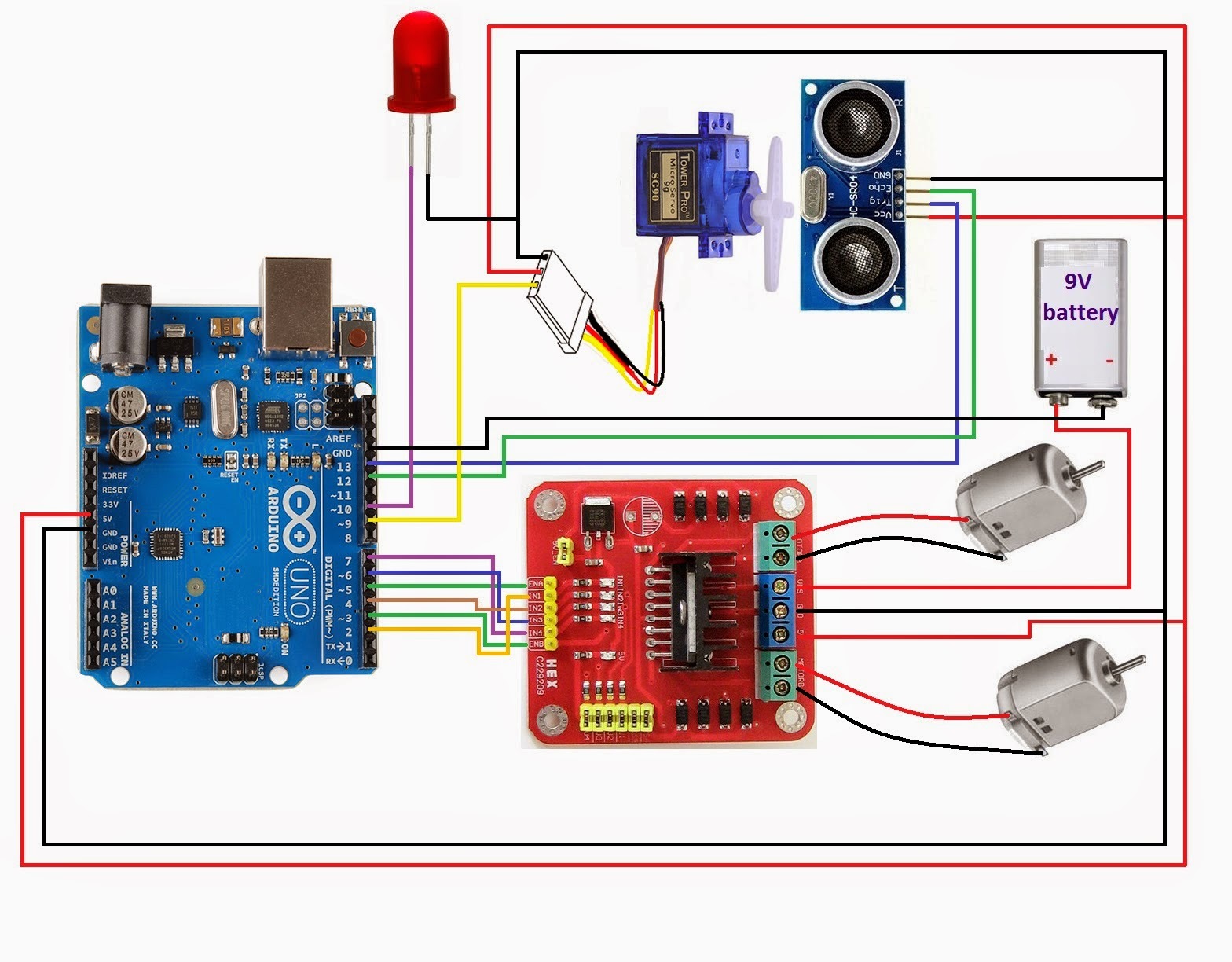
It should turn out like this:
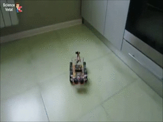
Sketch
#define Trig 8
#define Echo 9
#include <Servo.h>
Servo servo;
int ugol = 90;
int smotrim_vlevo = 0;
int smotrim_vpravo = 0;
int smotrim_priamo = 0;
int vremia;
const int in11 = 0; // L298N-1 pin 1
const int in12 = 1; // L298N-1 pin 2
const int in13 = 2; // L298N-1 pin 2
const int in14 = 3; // L298N-1 pin 3
const int in21 = 4; // L298N-2 pin 1
const int in22 = 5; // L298N-2 pin 2
const int in23 = 6; // L298N-2 pin 2
const int in24 = 7; // L298N-2 pin 3
void setup()
{
servo.attach(10); // 10
pinMode(Trig, OUTPUT); //
pinMode(Echo, INPUT); //
pinMode(in11, OUTPUT); // L298n
pinMode(in12, OUTPUT); // L298n
pinMode(in13, OUTPUT); // L298n
pinMode(in14, OUTPUT); // L298n
pinMode(in21, OUTPUT); // L298n
pinMode(in22, OUTPUT); // L298n
pinMode(in23, OUTPUT); // L298n
pinMode(in24, OUTPUT); // L298n
}
void ehat_priamo(){
digitalWrite(in11, LOW);
digitalWrite(in12, HIGH);
digitalWrite(in13, LOW);
digitalWrite(in14, HIGH);
digitalWrite(in21, LOW);
digitalWrite(in22, HIGH);
digitalWrite(in23, HIGH);
digitalWrite(in24, LOW);
}
void ehat_vpravo()
{
digitalWrite(in21, LOW);
digitalWrite(in22, HIGH);
digitalWrite(in23, HIGH);
digitalWrite(in24, LOW);
}
void ehat_vlevo(){
digitalWrite(in21, HIGH);
digitalWrite(in22, LOW);
digitalWrite(in23, LOW);
digitalWrite(in24, HIGH);
}
void stoiat(){ //
digitalWrite(in11, LOW);
digitalWrite(in12, LOW);
digitalWrite(in13, LOW);
digitalWrite(in14, LOW);
digitalWrite(in21, LOW);
digitalWrite(in22, LOW);
digitalWrite(in23, LOW);
digitalWrite(in24, LOW);
}
void kak_meriat_sleva(){
digitalWrite(Trig, HIGH);
delayMicroseconds(10);
digitalWrite(Trig, LOW);
vremia = pulseIn(Echo, HIGH);
smotrim_vlevo = vremia/58;
}
void kak_meriat_priamo(){
digitalWrite(Trig, HIGH);
delayMicroseconds(10);
digitalWrite(Trig, LOW);
vremia = pulseIn(Echo, HIGH);
smotrim_priamo = vremia/58;
}
void kak_meriat_sprava(){
digitalWrite(Trig, HIGH);
delayMicroseconds(10);
digitalWrite(Trig, LOW);
vremia = pulseIn(Echo, HIGH);
smotrim_vpravo = vremia/58;
}
void loop(){
kak_meriat_priamo();
if(smotrim_priamo<30){
stoiat();
delay (100);
for(ugol=90;ugol>=10;ugol--){
servo.write(ugol);
delay (5);
}
kak_meriat_sprava();
delay (100);
for(ugol=10;ugol<=170;ugol++){
servo.write(ugol);
delay (5);
}
kak_meriat_sleva();
delay (100);
for(ugol=170;ugol>=90;ugol--){
servo.write(ugol);
delay (5);
}
if(smotrim_vpravo < smotrim_vlevo){
ehat_vpravo();
delay(400);
stoiat();
}
else{
ehat_vlevo();
delay(400);
stoiat();
}
}
else{
ehat_priamo();
}
}
2WD . 4WD .
It should turn out like this:
22. Machine controlled from a smartphone
Connection diagram:

It should turn out like this:
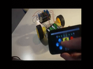
int val;
int LED = 13;
int LED2 = 11;
int LED3 = 12;
#include <AFMotor.h> //
#include <Servo.h> // ,
// M1, M2, M3, M4
AF_DCMotor motor1(1);
AF_DCMotor motor2(2);
AF_DCMotor motor3(3);
AF_DCMotor motor4(4);
void setup()
{
// ( PWM)
motor1.setSpeed(255);
motor1.run(RELEASE);
motor2.setSpeed(255);
motor2.run(RELEASE);
motor3.setSpeed(255);
motor3.run(RELEASE);
motor4.setSpeed(255);
motor4.run(RELEASE);
Serial.begin (9600);
}
int i;
void loop()
{
if (Serial.available())
{
val = Serial.read();
if (val == '5') // «5»
{digitalWrite(LED, HIGH);}
if (val == '6') // «6»
{digitalWrite(LED,LOW );}
if (val == 'Y') // «7»
{digitalWrite(LED2,HIGH );}
if (val == 'B') // «8»
{digitalWrite(LED3,HIGH );}
//
if (val == 'W') // «W»
{
// Motor Shield'
//
motor1.run(FORWARD); //
motor4.run(FORWARD);
motor1.setSpeed(255); //
motor4.setSpeed(255);
}
//
if ( val == 'S')
{
//
motor1.run(BACKWARD); //
motor4.run(BACKWARD);
motor1.setSpeed(255); //
motor4.setSpeed(255);
}
//
if ( val == 'D')
{
motor4.run(FORWARD); //
motor4.setSpeed(255); //
}
//
if ( val == 'A')
{
motor1.run(FORWARD); //
motor1.setSpeed(255); //
}
//
// «T»
if ( val == 'T') // «T»
{
motor1.run(RELEASE);
motor4.run(RELEASE);
}
if ( val == 'N') // «T»
{
// ENABLE ,
digitalWrite(LED2,LOW );
digitalWrite(LED3,LOW );
}
}
}
Connection diagram:
It should turn out like this:
23. Robot Vacuum Cleaner
- Android , RobotC, AppInventor.
«» , Bluetooth -.
: , , , , , , . , Bluetooth , Arduino , , - , Arduino.
«» - , «».
«» .
- , .
Connection diagram:

:
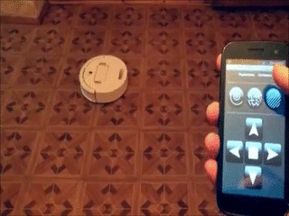
.
- Android , RobotC, AppInventor.
«» , Bluetooth -.
: , , , , , , . , Bluetooth , Arduino , , - , Arduino.
«» - , «».
«» .
- , .
#define mot_ena 9 //
#define mot_in1 8 //
#define mot_in2 7 //
#define mot_in3 6 //
#define mot_in4 4 //
#define mot_enb 10 //
#define ir_1 A0 // 1 -
#define ir_2 A1 // 2 -
#define ir_3 A2 // 3 -
#define ir_4 A3 // 4 -
#define ir_5 A4 // 5 -
#define ir_6 A5 // 6 -
#define lev_vik 11 //
#define pra_vik 12 //
//
byte max_skor_lev = 254;
byte max_skor_prav = 244;
//---------------------------------
byte min_skor = 0;
void setup() {
randomSeed(analogRead(A7));
//
pinMode(3, INPUT); //
pinMode(2, INPUT); //
//-------------------------
//
pinMode(mot_ena, OUTPUT);
pinMode(mot_in1, OUTPUT);
pinMode(mot_in2, OUTPUT);
pinMode(mot_in3, OUTPUT);
pinMode(mot_in4, OUTPUT);
pinMode(mot_enb, OUTPUT);
//-------------------------------------------
// -
pinMode(ir_1, INPUT);
pinMode(ir_2, INPUT);
pinMode(ir_3, INPUT);
pinMode(ir_4, INPUT);
pinMode(ir_5, INPUT);
pinMode(ir_6, INPUT);
//-------------------------
//
pinMode(lev_vik, INPUT);
pinMode(pra_vik, INPUT);
//---------------------------
delay(3000);
ROB_VPERED();
}
void loop() {
//
if (digitalRead(lev_vik) == LOW)
{
ROB_STOP();
delay(200);
ROB_NAZAD();
delay(150);
ROB_STOP();
delay(200);
ROB_PRAV();
delay(random(400, 1500));
ROB_STOP();
delay(200);
ROB_VPERED();
}
//-----------------------------------------------
//
if (digitalRead(pra_vik) == LOW)
{
ROB_STOP();
delay(200);
ROB_NAZAD();
delay(150);
ROB_STOP();
delay(200);
ROB_LEV();
delay(random(400, 1500));
ROB_STOP();
delay(200);
ROB_VPERED();
}
//-----------------------------------------------
// 2 -
if (digitalRead(ir_2) == LOW)
{
ROB_STOP();
delay(200);
ROB_PRAV();
delay(random(200, 1100));
ROB_STOP();
delay(200);
ROB_VPERED();
}
//-----------------------------------------------
// 3 -
if (digitalRead(ir_3) == LOW)
{
ROB_STOP();
delay(200);
ROB_PRAV();
delay(random(200, 1100));
ROB_STOP();
delay(200);
ROB_VPERED();
}
//-----------------------------------------------
// 4 -
if (digitalRead(ir_4) == LOW)
{
ROB_STOP();
delay(200);
ROB_LEV();
delay(random(200, 1100));
ROB_STOP();
delay(200);
ROB_VPERED();
}
//-----------------------------------------------
// 5 -
if (digitalRead(ir_5) == LOW)
{
ROB_STOP();
delay(200);
ROB_LEV();
delay(random(200, 1100));
ROB_STOP();
delay(200);
ROB_VPERED();
}
//-----------------------------------------------
// 1 -
if (digitalRead(ir_1) == LOW)
{
ROB_PRAV();
delay (10);
ROB_VPERED();
}
//-----------------------------------------------
// 6 -
if (digitalRead(ir_6) == LOW)
{
ROB_LEV();
delay (10);
ROB_VPERED();
}
//-----------------------------------------------
}
//
void ROB_PRAV()
{
//
digitalWrite(mot_in1, LOW);
digitalWrite(mot_in2, HIGH);
analogWrite(mot_ena, max_skor_lev);
//
digitalWrite(mot_in3, LOW);
digitalWrite(mot_in4, HIGH);
analogWrite(mot_enb, max_skor_prav);
}
//-----------------
//
void ROB_LEV()
{
//
digitalWrite(mot_in3, HIGH);
digitalWrite(mot_in4, LOW);
analogWrite(mot_enb, max_skor_prav);
//
digitalWrite(mot_in1, HIGH);
digitalWrite(mot_in2, LOW);
analogWrite(mot_ena, max_skor_lev);
}
//---------------------
//
void ROB_VPERED()
{
//
digitalWrite(mot_in1, LOW);
digitalWrite(mot_in2, HIGH);
analogWrite(mot_ena, max_skor_lev);
//
digitalWrite(mot_in3, HIGH);
digitalWrite(mot_in4, LOW);
analogWrite(mot_enb, max_skor_prav);
}
//-------------------------------------
//
void ROB_NAZAD()
{
//
digitalWrite(mot_in1, HIGH);
digitalWrite(mot_in2, LOW);
analogWrite(mot_ena, max_skor_lev);
//
digitalWrite(mot_in3, LOW);
digitalWrite(mot_in4, HIGH);
analogWrite(mot_enb, max_skor_prav);
}
//------------------------------------
//
void ROB_STOP()
{
//
digitalWrite(mot_in1, LOW);
digitalWrite(mot_in2, LOW);
analogWrite(mot_ena, min_skor);
//
digitalWrite(mot_in3, LOW);
digitalWrite(mot_in4, LOW);
analogWrite(mot_enb, min_skor);
}
//--------------------------------
Connection diagram:
:
.
24. Spider Robot (Hexapod)
, .

:
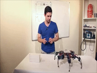
.
1
#include <Wire.h>
#include <Multiservo.h>
Multiservo myservo;
int pos = 0;
void setup(void)
{
Wire.begin();
myservo.attach(17);
}
void loop(void)
{
for (pos = 0; pos <= 180; pos += 1) // goes from 0 degrees to 180 degrees
{ // in steps of 1 degree
myservo.write(pos); // tell servo to go to position in variable 'pos'
delay(15); // waits 15ms for the servo to reach the position
}
for (pos = 180; pos >= 0; pos -= 1) // goes from 180 degrees to 0 degrees
{
myservo.write(pos); // tell servo to go to position in variable 'pos'
delay(15); // waits 15ms for the servo to reach the position
}
}
, .
:
.
At the moment, there is a search and selection of materials for classes 25-40. Links to Russian-language video tutorials with interesting projects on arduino can be left in the comments to the article.
Source: https://habr.com/ru/post/397019/
All Articles