Media player from the contents of the pantry

The author: Nikolai Khabarov
One fine Friday evening I decided to watch a movie at home: I turned on the laptop, connected the HDMI cable through the adapter with DisplayPort, picked up the remote, turned on the TV, started playback on the laptop. And I realized that the volume on the TV was insufficient - I had to look for the remote again to increase it ... Then I thought, “Is it possible to simplify this process somehow?”
Saturday morning was extremely fruitful. I decided to make my own network multimedia player, and this way I imagine it. Almost all the details were taken from the pantry, the heart of the player - Raspberry Pi. In more detail, that at it inside, and how to collect the similar device, look under a cat.
')

As you can see from the description, my requirements for the player are extremely simple: the ability to play content from the network, storage for several hundred gigabytes, the ability to control the same remote control as the TV; USB port is desirable but not required. Purchased players on Android disappeared immediately, since such devices are mostly pure China, in the worst sense of the word, and I had no desire to fight the bugs inside them. In addition, it is not clear how to implement the control of such a device from the TV remote, especially since the Android graphical interface is clearly not intended to control from the remote in principle. Therefore, the search began for junk from which to make things.
We select the details
First of all, I would like to just try and understand the feasibility of manufacturing the final device. Therefore, to begin with, we will take a minimum of details and test the potential media player at work. We go to the storeroom and literally dig up the parts we need:
1. Computer with HDMI-out. The old Raspberry Pi 1 is quite suitable for our purposes, you can also use the Raspberry Pi 2.
2. Power supply for the board - microUSB charging from the old phone will do. “To try” you can take any, but it is desirable to take a source that provides an output current of 1A (one amp will be enough for Pi 2 for the eyes, see requirements );
3. microSD card of 4 GB or more.
4. USB mouse and / or keyboard (can be wireless) and, optionally, an infrared signal receiver TSOP4836 or similar.
5. USB Wi-Fi-adapter or the ability to connect an Ethernet cable with the Internet to the board.
We put OpenElec, we try
At this stage, we will run OpenElec in the least possible form. Barely thinking about the software for my multimedia player, I remembered XBMC, later renamed Kodi . But the desire to put some kind of OSes, and then configure Kodi was not. So I decided to google and found this build of the GNU / Linux operating system, on top of which Kodi is already installed. This assembly is called OpenElec, it is an open source project. His official site is openelec.tv
So, download the installation image from the official site . Select the desired version and platform on which we will run it (in my case, the stable release for Rasberry Pi), and download the 'Diskimage' (file with the extension .img.gz).
Unpack the image:
$ gunzip -d < >.img.gz
And write to the memory card:
$ sudo dd if= < >.img of=/dev/mmblck0 bs=4M
Correct / dev / mmblck0 - if the memory card in your system is not one.
Attention! The contents of the memory card will be completely erased.
Windows users can use the free Win32 Disk Imager utility. The utility has a graphical interface - select a file, a memory card and click 'Write'.
Now we make sure that everything is written to the card by the command.
$ sync
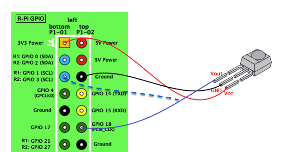
Or simply retrieve the card by safely removing the device in the OS GUI. We take it out physically and set it in the Raspberry Pi. Next, connect the Ethernet cable with the Internet or insert the USB Wi-Fi adapter, connect the mouse, HDMI cable to the TV. If you want to use an infrared remote, you need to connect the IR receiver to the GPIO18 and to the processor power supply (3.3V). The final wiring diagram is as follows:

If you decide to use an infrared receiver, be careful with it.
- make sure the location of the pins at your receiver.
Everything, now it is possible to look at the environment. We power the board from the power source. After downloading, the initial setup wizard will appear:
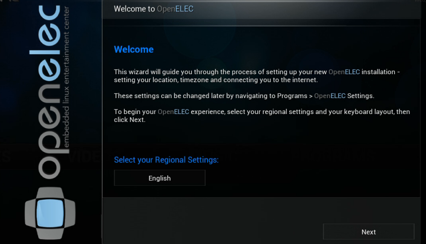
During setup I recommend to immediately enable SSH access. All other questions are trivial.
Now you can play with the environment of the future player using the mouse and / or keyboard. You can try to play video in various formats (you can connect a USB flash drive to the free ports) and generally understand what's what. There are various enclosures for the Raspberry Pi itself, perhaps someone will be satisfied with this minimalist look, for example, you can plug in a wireless USB mouse and use the device. We will continue to improve it.
Connecting the IR remote
If you decide not to connect the IR receiver, you can simply skip this section.
To use the remote, we need to configure LIRC . First, let's turn on the module that directly works with the receiver via the GPIO port. To do this, add a line to the DeviceTree config file. Login using SSH to your device (did you turn on SSH during initial setup? If not, you can do it in the graphical interface of the system itself).
$ ssh root@ip_address
The default password is openelec. Add the line we need to the file:
# mount -o remount,rw /flash
# nano /flash/config.txt
at the very end, add the line and then reload:
dtoverlay=lirc-rpi
Now we need to make sure that everything works and LIRC can receive commands from the console, for this we stop LIRC and try to obtain data from the console:
# killall lircd
# mode2 -d /dev/lirc0
We press on any button of the console and shine on the receiver - the text describing the incoming pulses should run in the console. Now we are convinced that everything works and we can train LIRC to use your remote control. I note that lircd must be stopped during the configuration process, we did it earlier using the kill command. For training there is a special utility irrecord, for its launch we execute the commands:
# cd /storage/.config
# irrecord -d /dev/lirc0 lircd.conf
Next, follow the instructions on the screen. At the beginning, the utility will ask you to press various buttons on the remote until the points on the screen are filled in order to learn the pattern of your remote. Then you will need to indicate with the text which button you want to train on the LIRC, and light it on the receiver.
I recommend teaching at least the following buttons:
KEY_UP
KEY_DOWN
KEY_LEFT
KEY_RIGHT
KEY_OK
KEY_PLAY
KEY_EXIT
KEY_STOP
KEY_INFO
KEY_EPG
The entire list of buttons available in the system can be obtained from the command:
# irrecord -list namespace
On the remote you can choose any buttons convenient for you. Most TVs in HDMI mode, most of the buttons do not do anything that we, of course, on hand. As a result, we should have a file lircd.conf with the parameters of your console - reload the board and try to use the console.
You can also turn on / off the player. To do this, you need to connect the receiver to the second output of the Raspberry PI GPIO1 for the Raspberry PI 1 or GPIO3 for the Raspberry PI 2 - on both the boards these pins are located in the same place of the board connector:
By connecting this pin to the ground, you can wake up the board, which is in the off state. With this connection, you can program the KEY_POWER button, and the player will turn off when you press it, and it will be turned on by any signal from any remote control.
We collect the device more seriously
I wanted to make a more solid device with the appearance of the factory device and add a hard disk to it. I looked into the pantry and found an old satellite receiver. Inside there is already a power supply sufficient for all components of the power, there is a receiver of the IR signal, the power switch to the rear. There is also an opportunity to make a clock on the front panel due to the seven-segment indicator already installed. And of course, the case itself is great for our purposes. The satellite receiver can be replaced by an old DVD or VHS player, even when not in use.
Attention, when disassembling the device, be careful with the power supply - it contains capacitors that can still be charged from the mains. And during subsequent assembly / adjustment, be careful when you turn it on - components on which there are 220 V are on the power supply board.
We open the receiver / video recorder. First we need to make sure that the power supply has a 5V output, which can provide the necessary power. To do this, using a multimeter, we check the presence of 5V power supply and then we trace what components these 5V are obtained. If the element base of the rectifier and the diameter of the transformer winding of the power supply unit are able to withstand 2-3 amperes, we are lucky - the source is there, otherwise we will have to change the source in the case to a more powerful one. Then we take out the main board / tape drive mechanism / optical drive and send it back to the storage room - it is still useful. Inside we leave only the power supply board and the board with the front panel, on which there is an IR receiver.
Now choose where to install the Raspberry Pi itself. The choice here is quite simple - the side of the board with HDMI should go outside the case, the side with USB ports should be mounted inside to connect internal components, besides, we need at least some access to the microSD card in case of a firmware change. There are holes for RCA connectors on the receiver's case; we will install the board so that the HDMI connector is maximally accessible from the outside. On the same side, there are outputs of a sound card and a microUSB operating in peripheral mode. These connectors are not interesting to us, we will power up the outside through the main GPIO connector of the board.
Mark up where you need to trim a little, so that the HDMI connector fits freely into the board outside the case and mark four holes for installing the board. I used these racks:
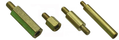
The stands of the native board were disturbed, and I removed them with the help of the pliers. Manipulations need to be carried out accurately, with awkward movement you can easily bend the body itself. We drill, saw, fasten with suitable rack bolts and the board itself.

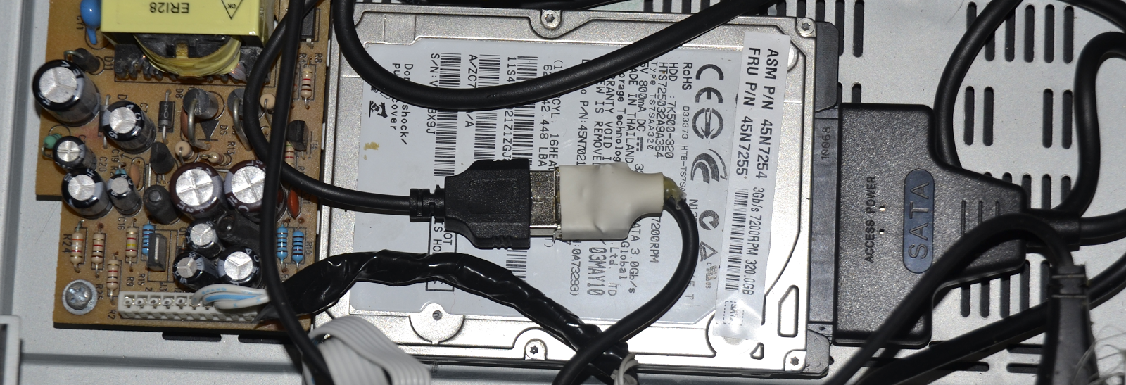
Now you need to find a place for HDD. Here, the requirement is quite simple - you need to leave a few free centimeters inside the case from the side of the SATA connector, since the adapter will be inserted there. The hard disk has a thread on the bottom and sides of the HDD. Winchester need a little lift, so that it does not lie on the metal. I solved the problem very simply - I took the bolts suitable for the lower thread, but a little longer than necessary, and laid the distance between the body and the HDD with larger nuts.
Now we need to find a SATA USB-converter or an old container for HDD, from where such a converter can be pulled out. I had a container, but unfortunately it turned out to be non-working. I had to run to the store for the SATA USB-converter. We will insert the USB connector into the Raspberry PI, but in order not to load the board, which the HDD requires, with rather serious currents, especially when spindle unwinding, we need to supply additional power directly from the PSU. In my case, the adapter had a cable with two USB connectors, I connected one of them directly to the power supply unit, decoupling the response USB connector next to the power supply unit.
Two more things to think about right away. The first is where and how the external USB port will be located. The second is where to install the Wi-Fi adapter, or if you plan to implement only an Ethernet connection, how to remove the Ethernet connector on the wall of the case (if you place the board with this connector on the case, you cannot connect USB devices from the inside). Ethernet can be extended by placing an ordinary wall socket inside the case and pressing a short wire with a connector.
Now tiny Wi-Fi USB dongles are being sold, but you shouldn’t put such inside of a metal case - it can be a bad signal. You can take a short USB extension cable, put the USB connector on the back of the case and insert it there. There are also USB-adapters with removable antennas, you can extend the RMA connector to the back of the case and screw the antenna there. I had a rather old and, as a result, a rather large USB Wi-Fi adapter with a twisted antenna and a miniUSB input. I had nowhere to put it because of its size, and I decided to use it in the business. I removed the case - its form did not allow to attach an antenna outside. The fee was quite large, and I had to think carefully about its placement. Fortunately, it turned out to be very thin, and I decided to put it above the USB connectors from the Raspberry Pi. RMA-connector out, twisted on the nut and inside the case put one high rack for the board. USB access remained, and the antenna was raised above the case. Fine!

Now you need to somehow fix the USB extension on the front panel, making sure that it does not interfere with anything inside the case. In my case, the receiver had a door for access cards, and I decided to put a connector for it - so as not to get dusty! Therefore, I didn’t cut it too neatly, but I poured hot melt on the back.

With the faceplate board, the situation is more interesting - the options for what it consists of are many. I had to implement a dynamic indication of seven-needle indicators using DMA (Direct Memory Access, a direct implementation of dynamic indication through GPIO ports would consume too many CPU resources, and the brightness of the segments would be uneven due to operating system activities). But this is a topic for a separate article, and besides, these boards can be completely different, so here we give the right to show their creative potential to the reader. You can study the source codes for my board . In the simplest case, you can simply cut the tracks going to the IR receiver, and solder to it directly with three wires. I note only that I used an IDE cable to connect to the GPIO connector of the board, it fits perfectly on the Raspberry Pi connector, and the wires can be easily unsoldered with other components.
In the end, I got this device:

Customize
If, when turned on, you see a colored square in the upper right corner of the screen, this means that the power supply for the Raspberry Pi is not enough - either a weak power supply, or too thin wires, or USB peripherals are taking too much away. In the first case, only the replacement of the PSU with a more powerful one will help. In the second, the problem is easily solved by replacing the wires with thicker or parallel using several wires; in the third, the problem is solved by powering USB devices directly from the PSU, or, for example, installing a USB hub with the ability to connect an external power source.
Also, you will surely see that your HDD is connected to the system as an external flash drive. Let's make it the primary repository in the operating system. When you first start OpenElec automatically begins to use all the free space on the microSD card under the data section, which is then mounted as / storage. The most successful solution seems to me to use the entire hard disk as / storage. To do this, format the hard disk and create a partition on it with the ext3 / 4 file system. This can be done directly on the player using the parted and mkfs utilities, the commands below will erase the entire contents of the disk and create one ext4 partition:
# umount /dev/sda1
# parted /dev/sda
GNU Parted 3.2
Using /dev/sda
Welcome to GNU Parted! Type 'help' to view a list of commands.
(parted) mklabel GPT
mklabel GPT
Warning: The existing disk label on /dev/sda will be destroyed and all data on
this disk will be lost. Do you want to continue?
Yes/No? yes
yes
(parted) mkpart primary 2048s 100%
mkpart primary 2048s 100%
(parted) q
q
Information: You may need to update /etc/fstab.
# mkfs.ext4 /dev/sda1
For this you will need to log in via SSH to the player. Then mount the new partition somewhere:
# mkdir /tmp/hdd
# mount /dev/sda1 /tmp/hdd
Copy the entire contents / storage to a new section to save the current state:
# cp -rf /storage/. /tmp/hdd
Unmount the partition and, if desired, delete the folder:
# umount /dev/sda1
# rmdir /tmp/hdd
Now you need to specify which disk we should mount at boot. This can be done by correcting the command line of the kernel parameters, but first we find out the UUID of our hard drive partition:
# blkid /dev/sda1
Copy the UUID of the partition to the clipboard. Now, we will remount the file system with the kernel config for writing and fix it:
# mount -o rw,remount /flash
# nano /flash/cmdline.txt
In the file, replace the disk parameter with the UUID of our disk. The contents of the file should get something like this:
boot=/dev/mmcblk0p1 disk=UUID=95013338-89b1-43af-8471-9b30efc85d98 quiet
After the reboot, the player will use the hard disk as / storage, and the partition on the memory card can be deleted so that it is not automatically mounted when booted:
# parted -s /dev/mmcblk0 rm 2
These were such fun days for me. Do not forget that on board this media player is the operating system GNU / Linux, and you can independently modify / add it as you please. You can also solve some home automation tasks using the same device.
And finally, a video of the author’s article about the device.
Enjoy all!
Source: https://habr.com/ru/post/396967/
All Articles