Interception of a call on the phone or how to make a simple radio control at 39 MHz
At the time of my studies at the university, it was necessary to do a term paper on electronics and microelectronics (such as the subject matter was exactly the name). There were two ways to solve this problem: take the finished task or invent your task for yourself. Also an important condition for the assignment was the development of the analog part of any device. Since I loved to do something of my own, and not some kind of imposed assignment , I decided to take the chance and took the radio control system as a topic for the course work, and as a result accidentally made a receiver for wiretapping radiotelephones.
The principle of operation of the analogue radio control
For single-channel equipment of discrete control, signal coding is performed by switching the radio transmitter on and off. However, I wanted something more complicated, and with the possibility of adding new control channels. Therefore, I decided to use the Durduino frequency coding of the signal since I did not know how to program the Durduino yet . Below is a block diagram of a multichannel radio control equipment.
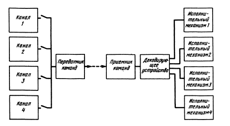
When frequency coding a signal, each channel has its own frequency. If the signal at this frequency is present, then the actuator works, if there is no signal, then it is logical that the actuator does not work. The transmitter simply transmits a signal with the necessary frequencies, and that's the whole principle of operation. But not everything is so simple. The fact is that due to the distortion of the signal by the receiver, or due to the characteristics of the transmitter itself, the control signal will most likely have harmonics that are multiples of its fundamental frequencies. Therefore, the frequencies of adjacent channels should not be multiples of each other, as well as the bandwidth of the filter that detects the signal of this channel so that the signal or harmonic from the adjacent channel does not fall into it.
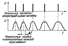
Formation of harmonics of the signal while limiting the sinusoidal signal

Low Frequency Bandwidth Breakdown for encoding and decoding a signal
To whom the details are interesting, I advise you to refer to the book: "Electronic Remote Control of Models", Gunter Mil, Moscow, DOSAAF USSR Publishing House 1980. Although this book is very old, it contains a lot of information regarding transmitting and receiving devices.
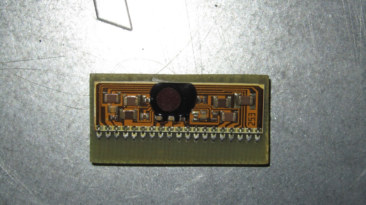
Receiver for receiving part of radio control
At first I wanted to make my compact radio. As a result, I assembled a super regenerator circuit, such as here . However, the superregenerator refused to work with me from the first kick, and therefore I decided to use a more complete solution in the form of the Soviet KHA058 chip. The choice fell on her for several reasons:
1) I already had this chip, and with the strapping.
2) It cost less than a modern Chinese chip.
3) Unlike the Chinese competitor, this chip has fewer elements for strapping and immediately earned.
4) The receiver IC operates in the VHF band.4) She has a cool look.

The scheme of inclusion of this chip was taken here , and its characteristics can be found here for example . However, I did not need the VHF band, so I decided to remake the oscillating circuit of the receiver at a frequency of 39 MHz. Why precisely on this frequency? In fact, one would almost like to take the frequency, given that I had a low-power transmitter. I once saw the frequency of 39 MHz on one radio control, and decided to use a ready-made remote control to test the receiver, which was with this frequency. In addition, this frequency is not prohibited for use in Russia . Transforming the receiver to a new frequency was not difficult, it was enough to determine the parameters of the oscillating circuit of the receiver and calculate it at 39 MHz.
Receiver testing and interception of important conversations
He turned on the receiver, but there was nothing to listen to, he began to tune the frequency, when suddenly I caught the conversation of two old women on the phone. It was fun.
Command Transmitter
The scheme of the transmitter, which I chose, could be called a transmitter quite arbitrarily. Rather, it was a generator with an antenna. The input LF signal changed the operation mode of the transistor, due to which the modulation of the signal worked. This approach is not very suitable for the transmission of high-quality sound, but for the transfer of commands I was quite suitable. I also amplified the transmitter by an output stage on one transistor. An example of a transmitter can be found here in Figure 13.6. Then I made the usual multivibrator at a frequency of 800 Hz, and connected it to the transmitter circuit. That's the whole control panel.
Command detector at the receiving part
From the book in the article above, I took the following diagram:
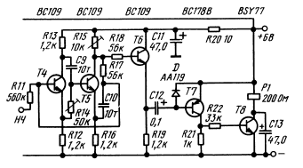
This is an RC filter with on-off switching cascade. Relay cascade I redid the LED display. Transistors took type kt315. The circuit was modeled in the CircuitMaker program, where I tuned it to a frequency of 800 Hz. The frequency of this filter depends on two RC chains: R14 C9 and R17 C10. R15 adjusts the sensitivity of the circuit, but here you have to be careful, the circuit may go into self-excitation. More information about the work of this scheme can be found in the book cited in the article above. In short, RC chains shift the signal in phase. If the shift is the same, the signal from the output gets to the input, it turns out we have a selective amplifier. If the situation is different, the signal may come altogether in antiphase.
PS I used this detector later in the order for the quest as a frequency detector of 8000 Hz (this is a whistle), who can use this solution.
Total
Everything worked, the LED on the receiving part of the radio control was lit when a command was transmitted to it. The transfer of any other frequency of the LED reaction did not cause. Teachers at the university called them Popov and, in general, check out the work well. True, such a radio control in practice can hardly be used, especially with the "quality" assembly that I had. But the case with the interception of conversations was fun. And of course, the main conclusion is that radio control is simple.
')
Source: https://habr.com/ru/post/396965/
All Articles