Switch Gira + Z-Wave. 4-button radio switch based on Z-Uno
What tasks solves the radio switch:
- In the room with the ready repair, the furniture was moved, the switchboard was closed by the cabinet
- At the stage of repair, they did not think out a convenient switch near the bed.
- In a timber house, it is not aesthetically pleasing to pull the external wiring, radio switches are required, but with a specific design
- Integration with existing automation system
At the moment, there are Z-Wave switches on batteries, for example Z-Wave.Me Wall Controller , but these switches come with a specific key design. If you want to use the switches Legrand, Gira, etc., then the Z-Wave Z-Uno board comes to the rescue.
')
I will show you how to make a radio switch on batteries, which can be installed in any convenient place, from the usual Gira switch. Video of the switch at the end of the article.
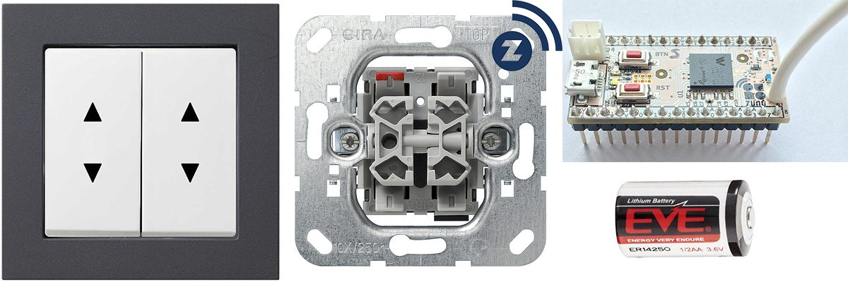
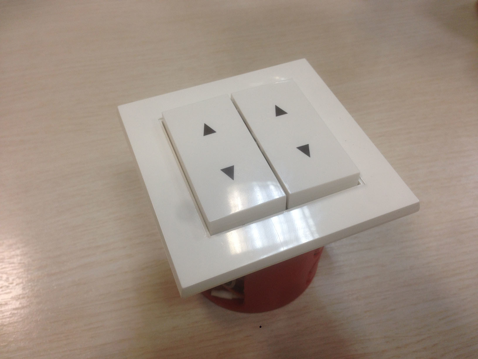
I use the Gira switch mechanism for blinds with 4 buttons and lock in the middle. I chose the design of the keys and frames from the System 55 series only because there are frames in the same design in the Z-Wave line of battery-operated switches .
Adding new features to Z-Uno is happening all the time, and in the latest release KeyScanner was added, which allows you to handle clicks from 112 buttons at the same time, I will limit myself to reading 4 buttons from the switch.
In the sketch below, Z-Uno in sleep mode waits for pressing one of the buttons, after pressing Z-Uno wakes up and sends a radio command, and then immediately falls asleep in order not to waste battery power.
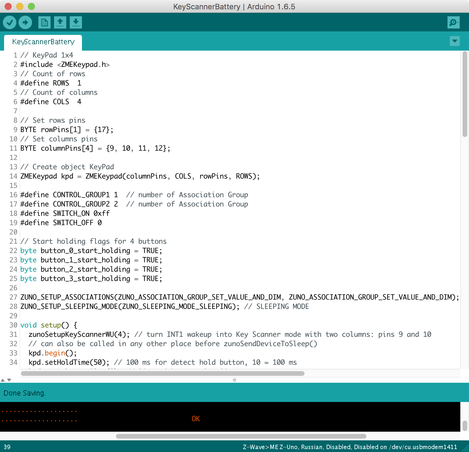
Sketch 4-button radio switch based on Z-Uno
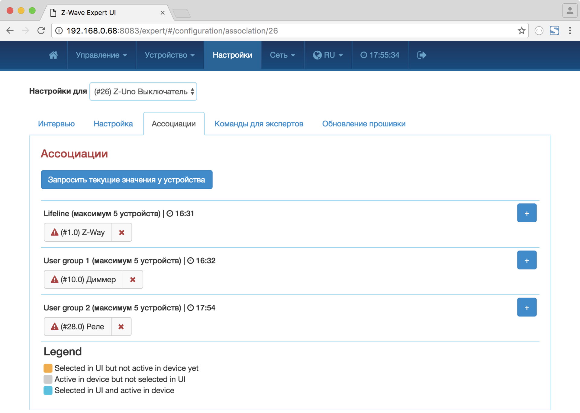
// KeyPad 1x4 #include <ZMEKeypad.h> // Count of rows #define ROWS 1 // Count of columns #define COLS 4 // Set rows pins BYTE rowPins[1] = {17}; // Set columns pins BYTE columnPins[4] = {9, 10, 11, 12}; // Create object KeyPad ZMEKeypad kpd = ZMEKeypad(columnPins, COLS, rowPins, ROWS); #define CONTROL_GROUP1 1 // number of Association Group #define CONTROL_GROUP2 2 // number of Association Group #define SWITCH_ON 0xff #define SWITCH_OFF 0 // Start holding flags for 4 buttons byte button_0_start_holding = TRUE; byte button_1_start_holding = TRUE; byte button_2_start_holding = TRUE; byte button_3_start_holding = TRUE; ZUNO_SETUP_ASSOCIATIONS(ZUNO_ASSOCIATION_GROUP_SET_VALUE_AND_DIM, ZUNO_ASSOCIATION_GROUP_SET_VALUE_AND_DIM); // Send Turn On/Off and Dim commands to associated devices ZUNO_SETUP_SLEEPING_MODE(ZUNO_SLEEPING_MODE_SLEEPING); // SLEEPING MODE void setup() { zunoSetupKeyScannerWU(4); // turn INT1 wakeup into Key Scanner mode with two columns: pins 9 and 10 // can also be called in any other place before zunoSendDeviceToSleep() kpd.begin(); kpd.setHoldTime(50); // 100 ms for detect hold button, 10 = 100 ms kpd.setDebounceTime(2); // 20 ms debounce, 2 = 20 ms } void loop() { byte actions[4]; // Array that return all actions from keypad (hold, release, press, double press, etc.) byte go_to_sleep = FALSE; // go to sleep after button released; // Default value for buttons - inactive, then read real states byte button_0_active = FALSE; byte button_1_active = FALSE; byte button_2_active = FALSE; byte button_3_active = FALSE; byte num_touched_keys = kpd.scanKeys(actions); if (num_touched_keys) { bool hold = KEYPAD_IS_HOLDING(actions[0]); switch (KEYPAD_KEYINDEX(actions[0])) { case 0: // Button Left Down button_0_active = TRUE; if (hold && button_0_start_holding) { // If button 0 start holding button_0_start_holding = FALSE; zunoSendToGroupDimmingCommand(CONTROL_GROUP1, TRUE, TRUE); // start dimming down (group, direction, start_stop) } if (!hold) { // If button 0 not holding go_to_sleep = TRUE; zunoSendToGroupSetValueCommand(CONTROL_GROUP1, SWITCH_OFF); } break; case 1: // Button Left Up button_1_active = TRUE; if (hold && button_1_start_holding) { // If button 1 start holding button_1_start_holding = FALSE; zunoSendToGroupDimmingCommand(CONTROL_GROUP1, FALSE, TRUE); // start dimming up (group, direction, start_stop) } if (!hold) { // If button 1 not holding go_to_sleep = TRUE; zunoSendToGroupSetValueCommand(CONTROL_GROUP1, SWITCH_ON); } break; case 2: // Button Right Down button_2_active = TRUE; if (hold && button_2_start_holding) { // If button 2 start holding button_2_start_holding = FALSE; zunoSendToGroupDimmingCommand(CONTROL_GROUP2, TRUE, TRUE); // start dimming down (group, direction, start_stop) } if (!hold) { // If button 2 not holding go_to_sleep = TRUE; zunoSendToGroupSetValueCommand(CONTROL_GROUP2, SWITCH_OFF); } break; case 3: // Button Right Up button_3_active = TRUE; if (hold && button_3_start_holding) { // If button 3 start holding button_3_start_holding = FALSE; zunoSendToGroupDimmingCommand(CONTROL_GROUP2, FALSE, TRUE); // start dimming down (group, direction, start_stop) } if (!hold) { // If button 3 not holding go_to_sleep = TRUE; zunoSendToGroupSetValueCommand(CONTROL_GROUP2, SWITCH_ON); } break; } } if(!button_0_start_holding && !button_0_active) { // If button 0 release holding button_0_start_holding = TRUE; zunoSendToGroupDimmingCommand(CONTROL_GROUP1, TRUE, FALSE); // stop dimming down (group, direction, start_stop) } if(!button_1_start_holding && !button_1_active) { // If button 1 release holding button_1_start_holding = TRUE; zunoSendToGroupDimmingCommand(CONTROL_GROUP1, FALSE, FALSE); // stop dimming up (group, direction, start_stop) } if(!button_2_start_holding && !button_2_active) { // If button 2 release holding button_2_start_holding = TRUE; zunoSendToGroupDimmingCommand(CONTROL_GROUP2, TRUE, FALSE); // stop dimming down (group, direction, start_stop) } if(!button_3_start_holding && !button_3_active) { // If button 3 release holding button_3_start_holding = TRUE; zunoSendToGroupDimmingCommand(CONTROL_GROUP2, FALSE, FALSE); // stop dimming up (group, direction, start_stop) } // if all buttons released if (kpd.isIdled()) { go_to_sleep = TRUE; } if (go_to_sleep) { zunoSendDeviceToSleep(); } } // Z-Uno 2.0.6 /Volumes/Files/user/Library/Arduino15/packages/Z-Uno/hardware/zw8051/2.0.6/libraries/ZMEKeypad/ZMEKeypad.h "BYTE isIdled(){return mon_keys == 0;};" 55 The recipient of the radio command is configured to each of the 4 buttons using associations; it can be a relay , a dimmer , an RGBW tape , an LED lamp, or another actuator. In the sketch, I create 2 groups of associations to control 2 devices, the upper buttons send power-on commands, the lower buttons send power-off commands.
We connect the mechanism of the GIRA switch to the Z-Uno 1,2,3,4 pins. Included with the Z-Uno is a plug, I soldered it to the battery compartment 1/2 AA and plugged it into the battery connector. The 1 / 2AA battery (ER14250) is a compact, capacious 3.6 V battery, but you can use 2 AA batteries, they also fit perfectly into the box.
Z-Uno has 2 DC-DC converters, they are not required when running on batteries, so you can exclude them from the power circuit by disconnecting the jumper R12. At the same time, the power consumption of Z-Uno in sleep mode is reduced by 143 times, from 1 mA to 7 μA.
Podozetniki recommend 60 mm deep, it is more convenient to work with them, pushing the Z-Uno with a battery, wires and the switch itself is difficult in 40 mm but it is possible!

The 2 right buttons control the outlet, send ON and OFF commands to the Z-Wave.Me outlet .
The 2 left buttons control the dimmer, with a short press, the ON and OFF commands are sent, and with a long hold on the UP or DOWN, dimming commands are sent to the Z-Wave.Me dimmer .
As you can see, the battery device that reads the state of the buttons with the Z-Uno is made very simple, and this way you can connect the whole keyboard to the Z-Uno, where each button will perform the useful function of your smart home.
Video of operation of the battery switch based on Z-Uno. Dimmer and relay control.
Source: https://habr.com/ru/post/396839/
All Articles