50 shades of stub * Microchip microcontroller I / O ports
- POIs - Peripherals Independent of the Core in Microchip microcontrollers, also known as CIP - Core Independent Peripheral.
The previous article [ 1 ] (let's call it “part 1” of a series of articles, since I hope that there will be enough enthusiasm and strength for several articles) was devoted to the most obvious part of the Microchip Core Independent Microcontroller (MC) Core — configurable logic cells.
UPD. here is part 3. ADC with calculator
Now let's look at some of the features of I / O ports and especially those that can help in the implementation of specific functions and simplify the construction of circuits using PIC microcontrollers.
Content
- Standard port functions
- Reassigning the functions of input / output ports, PPS
- control of current output driver port, CCDM
- examples of using
- reliability, self-diagnosis
- multivibrators (generators)
- sawtooth generator
- PWM modulator
- D-class amplifier
Standard port functions
I / O ports can be called Peripheral Independent of the Kernel, since the port inputs are asynchronous, the state of the ports is kept in the sleeping state of the kernel. Probably it is difficult to find unique opportunities at the “port” periphery, but some of the “chips” still deserve attention.
Ports of modern PIC microcontrollers have a set of standard features:
- Analog inputs
- ADC inputs
- comparators inputs
- operational amplifier inputs
- voltage reference inputs
- Analog outputs
- OU outputs
- D / A Outputs
- voltage source outputs
- Digital inputs
- setting the type of input TTL or ST (trigger Schimtt)
- the possibility of including internal braces to Vdd
- voltage source outputs
- Digital outputs
- standard output or open drain type
- the possibility of limiting the rate of rise of the front / fall (a useful feature to reduce EMI interference)
- high output load capacity (usually, for PIC controllers, the inflowing / flowing current has an upper value of 25mA, but in some families the load capacity of a pair of port pins is increased to 50 or even 100mA)
Reassigning the functions of input / output ports, PPS
Among the “non-standard”, but very useful features, the possibility of reassigning port functions (Peripheral Pin Select, PPS) should be noted.
The reassignment of port functions is interesting in that it provides the following features:
- optimization of the PCB trace - the developer can “drag” certain inputs / outputs of the periphery along the controller pins
- reduction of interference (you can maximally remove high-frequency digital outputs (PWM, interfaces, etc.) from analog circuits
- the most complete use of the periphery (Microchip microcontrollers have always been famous for the abundance of peripheral modules, but due to the limited number of pins of microchips, the developer did not always manage to use the set of peripherals he needed, since different peripherals could use the same output of the microcircuit, i.e. donate something)
- increasing the load capacity of the port - the output of the periphery (UART, PWM, etc.) can be connected to several ports of the MC; these ports can be connected on the board and thereby increase the load capacity
- combining functions on one pin (for example, the same input can be connected to the UART input and the interrupt input)
- testing and debugging. You probably already guess (or did I write about this earlier ??) that in the concept of a DEC, the periphery can be connected inside the MC and not have exits. This is great for the final debugged device, since it minimizes the size of the MK case and the product (and hides the ability to understand the internal logic of the stub operation from competitors), but at the debugging stage it is useful to bring some of the “test” signals through the PPS and debug the hardware.

Fig.1. PPS configuration example in MPLAB X IDE development environment
Control current output port drivers
In some newer families, such as the PIC16F18855, a function hitherto unheard of in the PIC appeared - control of the output driver current, i.e. control of flowing / flowing current (Current-Control Drive Mode, CCDM). Now you can set what current will flow or flow into the port. When this mode is enabled, for each output of the microcontroller, it is possible to turn on the current control, and it is possible to individually enable the monitoring of the inflowing and outflowing current.
There are not so many options for the values of the currents - you can choose the values of 1, 2, 5 and 10 mA, in addition, the selected value will be the same for all monitored outputs.
But, control of the current output port drivers gives a lot of possibilities:
- self-diagnosis, reliability;
- reducing the number of current-limiting resistors on the board, simplifying the printed circuit board;
- reduction of radiated interference;
- possibility of forming sawtooth signals
- ... (to come up with more? ;-)
Best of all you can experience the possibilities of new functions of the ports with specific examples.
Examples
Reliability, Self Diagnosis
Suppose a short circuit occurred on the board between two ports configured for output. If one port is able to log.1, and the second to log.0, then a current will flow through the port. With a load capacity of up to 25mA (actually up to 50mA), a large current will flow through the ports, which can lead to a port or controller failure.
The current limit function can prevent damage to the port.
In addition, you can organize the diagnosis of ports, the definition of load.
If necessary, testing the port using similar schemes (see Figure 2). In this case, you can give a signal to one port and consider the status of the other output port. In principle, due to the structure of the Microchip MK ports, it is possible to test without an external resistor (send a log level to the port and read the input of the same port), but there will be no current limit on the output short-circuit.

Fig.2. Self-testing of the port MK.
With the port current limiting function, we can provide safe testing of the port, since the short-circuit current will be limited by the CCDM function.

Fig.3. Self test using port current limit.
For example, in the program, we configure the port (RC7) to an output with current limitation, feed log.1, then read the state of the same port at the input.
We can read both in digital form and with the help of an ADC, and in the second case we can determine the load resistance (since the supply voltage and the current through the port are known).
| digital input testing | testing ADC |
|---|---|
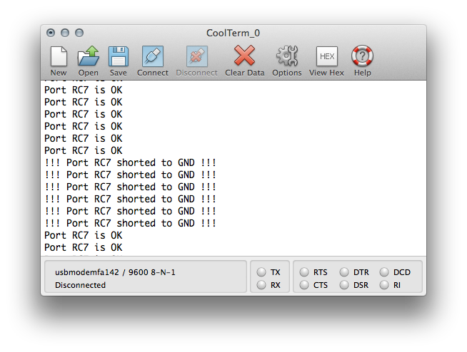 | 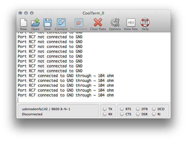 |
Fig.4. Output RC7 port testing information to the terminal.
Generators
In the previous article devoted to CLC, we have already considered various kinds of oscillators / multivibrators, consider how CCDM and PPS will simplify even before that simple schemes based on the PLC (CLC).
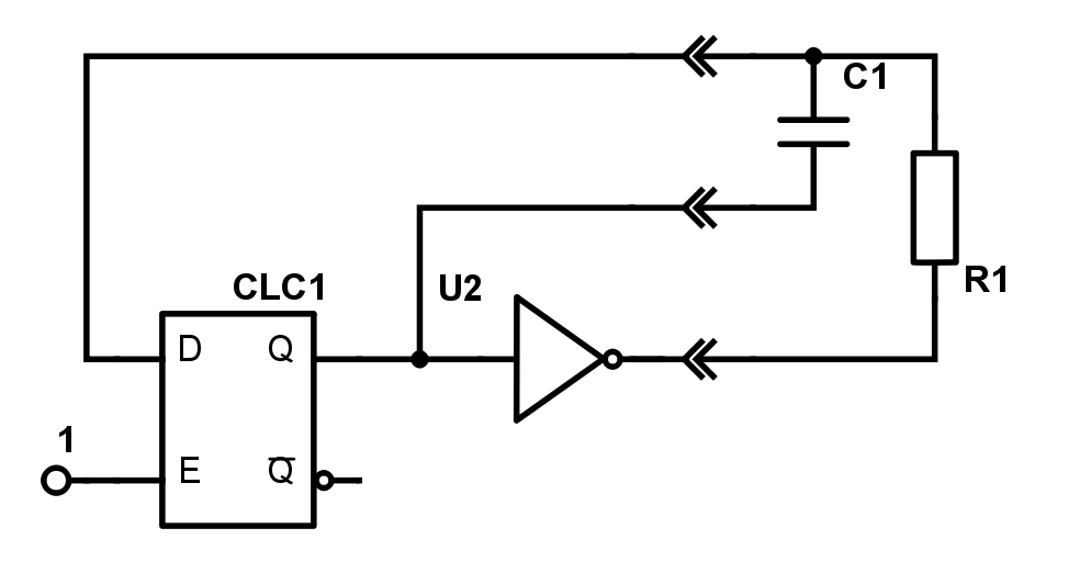
Figure 5. Multivibrator on two gates.
Figure 5 shows the previously considered generator on the D trigger, the inverter and the RC chain (in this case, the circuit is slightly redrawn to display connections external to the microcontroller). The generator frequency is determined by the parameters R and C. Resistor R sets the charge / discharge current of capacitor C. Now, if there is an integrated controller for the current port driver, we can remove the resistor and slightly simplify the circuit.
Note Further in the figures, the output of the port with the CCDM function will be denoted as a resistor with the CCDM signature
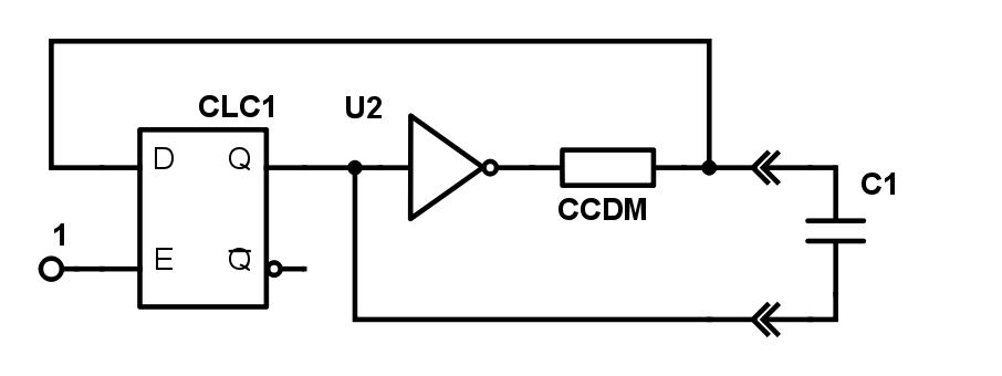
Fig.6. Multivibrator with limited output current port CLC2
It should be noted that it is not at all necessary for the CLC1 to use the D trigger, any variant of the non-inverting gate implementation will go.
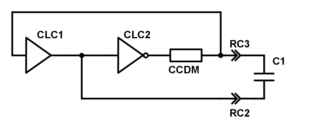
Fig. 7. Another version of the multivibrator on two logical gates.
The ability to get rid of one resistor is not the purpose for which it would be worth considering this topic, but in this example we additionally have the following:
a decrease in the number of outputs used by the MK (yes, you remember that we have a part of the POU in the form of a PPS), that is, for the same case we can have more opportunities - to cram more into less.
- the possibility of software frequency changes! If we change the charge / discharge current of the capacitor, then we change the rate of change of the voltage on the capacitor, which means the switching frequency of the multivibrator.
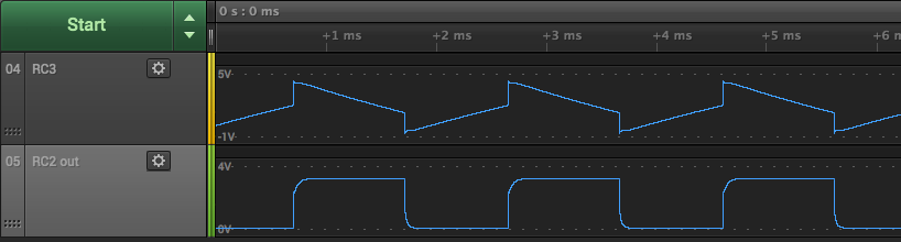
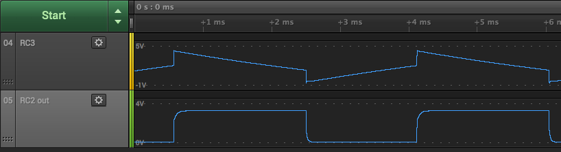
Fig. 8. Current control allows you to programmatically change the frequency of the multivibrator.
In the original circuit, the microcontroller would need 3 pins, a modified circuit using PPS and CCDM only requires 2.
In fact, the multivibrator can be made on one gate (Fig. 9), then the microcontroller will need only one external output. The CLC output can be connected inside the MC to other peripherals. On the capacitor, we will see a triangular signal, but we can make sure that a sequence of “zeros” and “ones” is still present at the output of the CLC if the output of the same CLC is output to another “control” output of the MC using PPS.
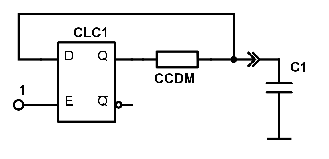
Fig.9. Multivibrator on one gate
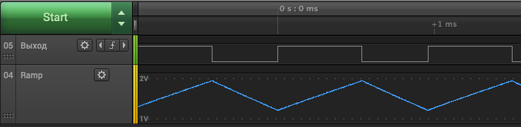
Fig.10. The waveform on the multivibrator capacitor and the control output of the logic element.
Sawtooth generator
For the mode of control of the current driver of the port, we can set the fixation of the inflowing and flowing out current. In the diagram in Fig.9, both currents are controlled. If we turn on the control of the outgoing current only, we get the following picture (Fig. 11).

Fig. 11. Generator sawtooth voltage.
That is, in this case, the capacitor is charged with a limited current of 1mA, and discharges through the port without a current limit (note that the maximum permissible current for the port is 50mA, so a series resistor may be needed to limit the current).
As you can see from the diagrams (fig. 10 and 11) on the capacitor we get a saw, the upper and lower voltage values of which lie between the levels log 1 and 0 of the digital inputs.
If we want to increase the amplitude, then we can additionally use two internal comparators (in part 1 we have already considered this generator circuit). Now we will repeat this scheme, but using the output port driver current control function (CCDM), i.e. without an external resistor and with a reduced number of enabled I / O ports.
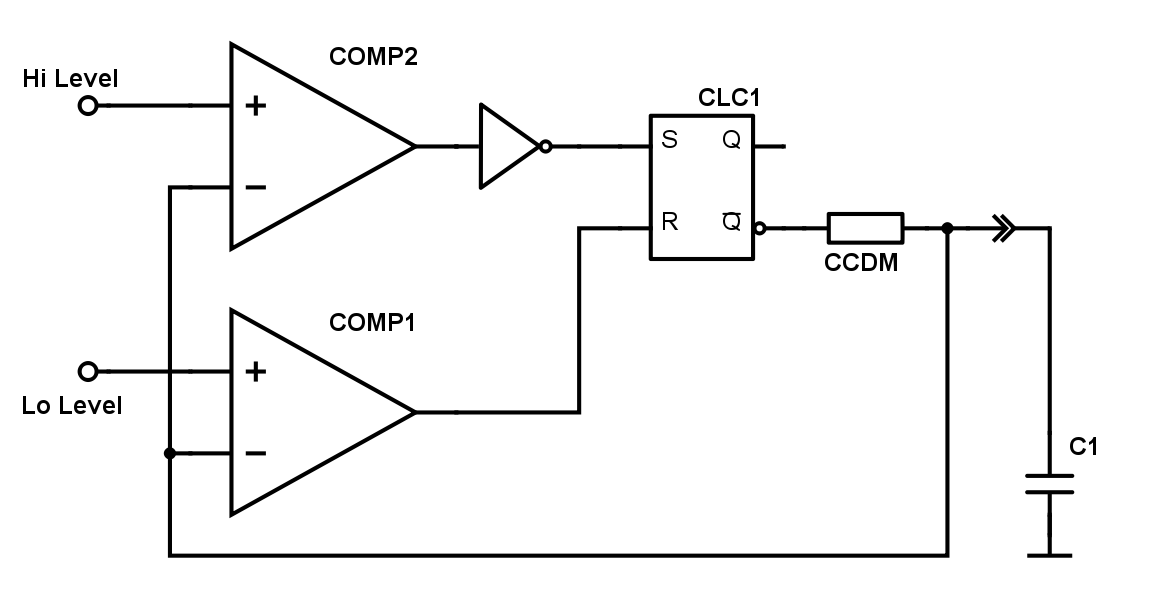
Fig.12. Multivibrator with comparators.
Due to the current control, we obtain a more linear sawtooth voltage generator than in the previously considered similar circuit (see [1]).
As for the previous version of the multivibrator, we can change the frequency programmatically by changing the port current.

Figure 13. Multivibrator output
Voltage controlled generator
If you change the reference voltage on the comparator, then we get a voltage controlled oscillator. The support of the comparator can be changed as a built-in DAC, and served from the external circuits of the microcontroller.
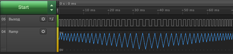
Fig. 14. Changing the frequency of the generator by changing the reference voltage of the comparator.
The multivibrator circuit on two comparators and the RS flip-flop can be slightly optimized. Leave the lower threshold of the circuit (input R trigger) with control from the comparator, and the second from the port (S trigger input).
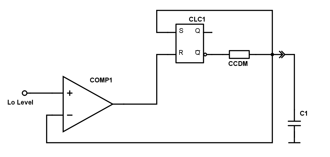
Fig. 15. Multivibrator version with one comparator.
The released comparator, in conjunction with the saw generator built, can be used to build a PWM modulator.
PWM modulator
So, now if we apply a sawtooth-varying voltage to one input of the comparator, and a “reference” voltage to the other, we will get a PWM modulator. The duty cycle of the PWM will be determined by the level of the threshold voltage, and the frequency is determined by the frequency of the saw.
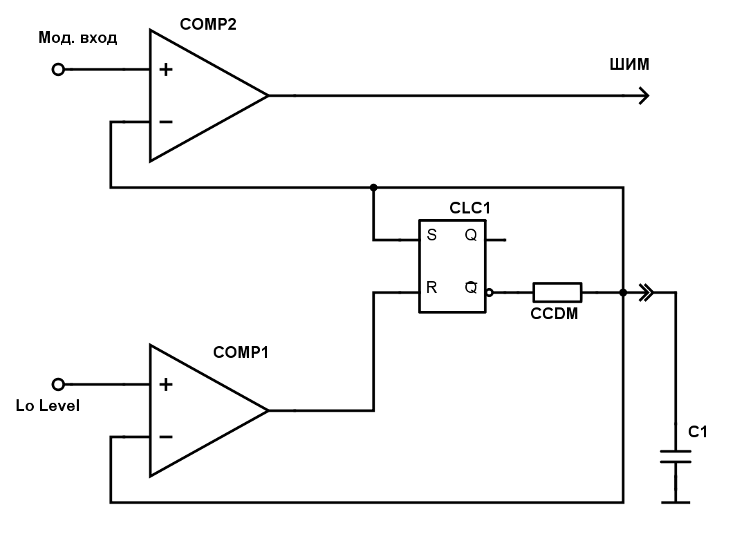
Fig. 16. PWM modulator of the saw generator and comparator.

Fig. 17. Diagram at the output of the PWM modulator.
D-Class Amplifier
The frequency of the saw considered generators is determined by the capacitance C and the current port. We can form a saw with a frequency of hundreds of kilohertz.
The reference signal can be both external and be formed, for example, a built-in DAC. If the reference signal comes from a sound source, then we have very little left to build a Class D amplifier.
Microcontrollers of the PIC16F188xx series have a Complementary Waveform Generator (CWG) module, which can generate bridge control signals from the input signal.
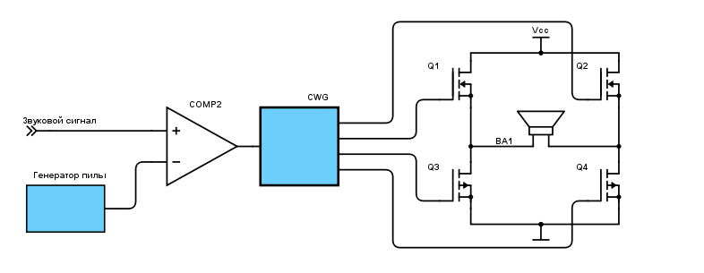
Fig. 18. Diagram of a class D amplifier on a microcontroller using CIP.

Fig. 19. Diagram of amplifier signals.
So, from such parts of the PSI as a port with CCDM Output Current Control, Configurable Logic CLC Cells, Comparators, DACs, CWG Complementary Shaper, we got a class D amplifier.
Results
We looked at another part of the Peripheral Independent of the Core — the I / O ports of the Microchip microcontrollers. Most features, including reassignment of pin functions, are present in many PIC16F1xxx families, but a new “feature” - CCDM (current control of the output port driver), appeared quite recently in the PIC16F188xx family (PIC16F18855, etc.).
Independence from the core is that we only need to initialize the necessary capabilities (PPS, CCDM, etc.), the rest of the operation does not depend on the clock frequency and the state of the MK core (Run, Sleep, Idle or Doze). But in the process of work, we, nevertheless, have the opportunity to change the functioning of such a periphery.
The periphery independent of the core is interesting in and of itself, but the possibility of synthesizing functional blocks, i.e. sharing of several peripheral modules for solving specific tasks. In this case, the clock frequency, speed, and bit depth of the core go into the background - the hardware performs specialized functions, and the core deals with software support for the product.
Literature:
- Configurable Logic Cells in PIC Controllers. https://geektimes.ru/post/278718/
- PIC16 (L) F18855 / 75 Data Sheet. www.microchip.com
- TB3140. Programmable Ramp Generator Technical Brief. www.microchip.com
')
Source: https://habr.com/ru/post/396645/
All Articles