Creating a system of access restriction in the FLProg program using RFID-RC522
Good day. I am the developer of the FLProg program, and today I will tell you how to create an access control device using the FLProg program using the RC522 RFID tagless scanner. Since this post is a training, then it will not be considered a finished product, but only a test layout.
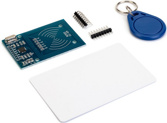
Consider this RF5 RC522 contactless tag scanner.
')
RFID-RC522 contactless tag scanner without tags allows you to detect and read IDs of contactless cards, tags, 13.56 MHz gaps at a distance of 10 cm. With this scanner you can make a number of interesting projects: access systems, electronic locks, inventory control and much more .
Technical characteristics of the scanner.
| Parameter | Value |
|---|---|
| Current consumption in active state | 13-26mA / DC 3.3V |
| Standby current consumption | 10-13mA / DC 3.3V |
| Sleep current | <80uA |
| Operating frequency | 13.56MHz |
| Supported Card Types | MIFARE S50, MIFARE S70, MIFARE UltraLight, MIFARE Pro, MIFARE DESfire |
| The size | 40mm x 60mm |
| The temperature at which the module operates | -20 to +80 |
| Relative humidity | from 5% to 95% |
The basic principle of operation is quite simple to understand. There are antennas in the card and in the reader, and the signal of the reader (the essence of the electromagnetic field) simultaneously serves as the power source for the card. Those. And in terms of energy, and in terms of data transfer, this is very similar to the super-popular wireless charges.
The cards themselves, depending on the modification, can carry from a few tens of bytes to several kilobytes of data (including a unique serial number). Also, depending on the modification, the card can be equipped with cryptographic information protection.
In China, such scanners cost from 200 rubles, complete with a card and a remote control. It is very attractive. But still, when ordering this scanner, I advise you to take it, as they say "with a margin." In my case, out of the three scanners I have, purchased at different times from different vendors, normally earned only one. The second saw the map, only brought up exactly at a certain distance. Closer or farther - he lost it. Well, the third one didn’t see the presented cards at all, although SPI responded normally to queries and testing.
The program FLProg implemented two types of functional blocks to work with the scanner.
Blocks directly associated with the scanner
- "Availability of a new card"
- "Map Information"
- "Read data on the card"
- "Writing a block of data to the card"
The blocks associated with the scanner are indirectly designed to work with the storage of UUID cards.
The program implements the storage of UUID cards, which is a set of cells, each of which stores directly the UUID of the card, and the status of the cell. Three statuses reserved by the program.
0x00 - the cell is free
001 - UUID is stored in the cell, but it is locked.
0x02 - the UUID is stored in the cell and it is active
The rest of the status codes (3 ... 255) can be used by the user at his own discretion.
The storage can be located in the RAM of the controller (when power is removed or it is reset, it will be cleared), or in the EEPROM. There may be several storages, and they may be of different types. When the storage is located in the EEPROM, its dimensions are limited. For Arduino, Uno is a maximum of 85 cells (in all EEPROM storages in total), for Arduino Mega - 341 cells.
Storage units
- “Save UUID Cards to the Vault”
- "Read UUID cards from storage"
- "The status of the cell in the repository"
- "Write cell status to storage"
- "Lock / Unlock Cell"
- "Search UUID in storage"
- "Free storage cells"
- "Clearing a cell in storage"
- "Clearing the entire repository"
Let's sort out the technical specifications for the device.
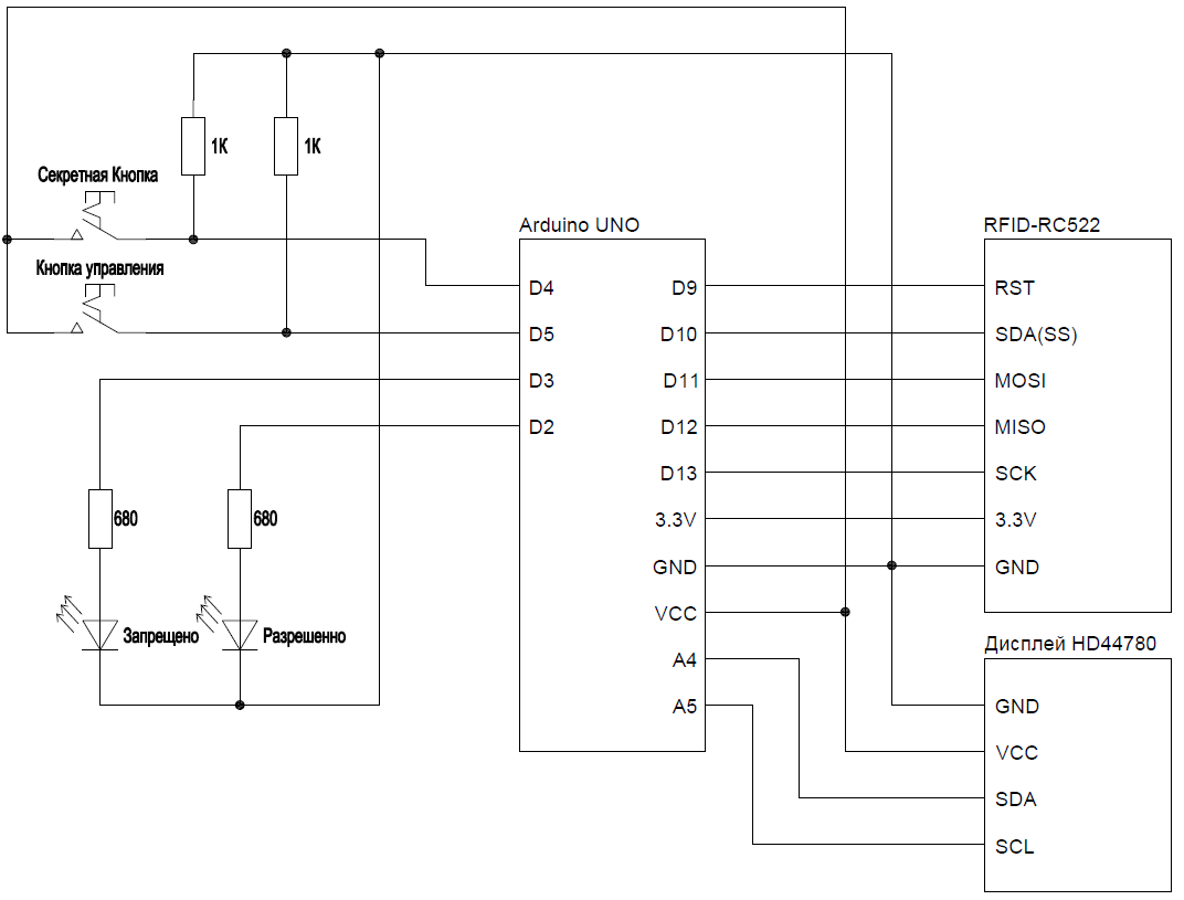
The device will have two repositories located EEPROM. The first one stores the so-called Master Card. Using them, you can write the usual cards in the second repository. There is a “Secret Button” for recording Master Card. There is also a display to display the necessary information, and the usual control button.
Scheme of the device.
Video lesson describing the result of development
A project created in class with FLProg.
Cards and keyfobs used with the scanner have onboard 1 KB of memory that can be used for their own purposes. Let's expand the TK and record any information. To do this, we will assemble another device.
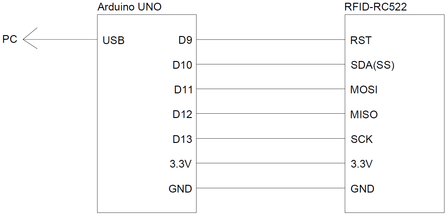
We will also finalize the project created in the previous video tutorial.
FLProg recording device design.
Modified project from the first video of the lesson.
Goodbye, I hope you were interested.
Source: https://habr.com/ru/post/396501/
All Articles