Quests in reality - "Not by bread alone ..."
Greetings to all who may find this article helpful. Although of course, now the “quest rooms” are far from the peak of their popularity, and the new generation of “quests in reality” uses completely different technologies. But I sincerely hope that someone will be able to learn for themselves from this publication and apply it in everyday life.
The idea of writing this article was born quite a long time ago: the development and implementation of electronics and automation for 5 questrooms is behind us. Communication with colleagues in the shop showed that many of them use simpler solutions and much more serious solutions when building quests. Since I do not pretend to a certain competence or authority in the development of electronics, this article makes sense to transfer experience, and is an attempt to talk about my own vision of the use of automation of the type "DIY" in the field of entertainment.
So, let's begin. For those who do not know, “quests in reality” is a type of modern entertainment, where for a certain time a team of players are offered to find a way out of the “custom” location, simultaneously solving various tasks and missions assigned to them. Starting from the room with the door, and a bunch of mechanical code locks, the “quest rooms” evolved into a huge “show monster”, combining elements of theatrical performance, performance, 3-d shows, attractions, etc. Creating such quests requires considerable financial investments and efforts. And now I will tell you how we built a similar quest, without using industrial solutions in automation and ensuring interactivity, because such things would cost in an amount that is an order of magnitude higher than those we spent on building the entire location along with the tweaking of the reception. In order to keep commercial secrets, I will not be able to name either the name of the questroom itself, or the company, or show photos of the implemented puzzles and devices. But still, I can show something, and try to tell everything in as much detail as possible in this article.
First of all, I’ll try to outline the very implementation scheme of the automatic questroom. It consists of such components as:
- implementation of game mechanics (devices, puzzles, sensors, actuators);
- the implementation of interactivity (voice actions of the players in the quest, playing videos, lighting control);
- implementation of the quest management (preparing the quest for work and managing the game and service functions of the electronics);
')
To implement the game mechanics in the role of actuating devices, elements such as electromagnetic and electromechanical locks, electric motors, smoke machines, LED and luminescent lighting, pneumatics, and stepper motors were used. The sources of signals are motion sensors, reed sensors QMS, RFID readers, photo detectors, electro-technical buttons and limit switches, variable resistors, resistive sensors.
All actions and events that occur during the game in the quest are voiced, just as it happens in any video game. The interactivity of what is happening is implemented in the format: PC, to which 2 class AB + 6 car speakers are connected, giving a total power peak of 800 watts. Also, 2 LCD monitors are connected to a PC running the good old Win7, which play video clips at certain game moments, and at some other time display some static screens. And oddly enough, the whole kitchen works and is controlled by an AVR Atmega 2560 microcontroller, carefully soldered to the ** Arduino Mega 2560 board ** by our friends from a nearby but well-known state. But first things first. In total, the quest uses the following electronics and automation:
- 6 motion sensors;
- 15 reed sensors QMS;
- 4 resistive sensors made of foil textolite;
- 3 electric motors from the glass-lifting mechanism of cars;
- 1 smoke machine;
- 1 compressor with receiver for pneumatic operation;
- 2 Camozzi pneumatic cylinders + all strapping for air preparation and control;
- 23 buttons to enter codes in the keypad puzzles with the input code;
- ultrasonic distance measuring sensor HC-SR04;
- noise sensor for Arduino on a condenser microphone with a comparator;
- asynchronous three-phase brushless motor 380 V;
- about 50 meters of LED strips;
- 33 LEDs 1 Watt;
- 4 10 Watt LEDs to illuminate the room in the lamps;
- 3 LED lights;
- 15 Arduino boards (Uno, Mega 2560, and Pro Mini);
- 16 boards of modules, manufactured and developed independently for this quest;
- 2500 meters of cable UTP Cat-5e, SHVVP and PUGNP;
- 1000 meters of MGTF cable for cross-connecting electronics and modules with each other;
- 2 car amplifiers with a total capacity of 800 watts;
- 6 car coaxial speakers, each with a peak power of 120 watts;
- 2 three-phase contactor 5 Ampere;
- 8 solid-state relays with a load capacity of 25 Amps;
- 1 PC (x64) based on Windows 7;
- and a bunch of different uninteresting, but necessary little things.
For a start: about interactivity. All events and actions of players inside the quest are voiced (opening doors, penetrating rooms, working out sensors and sensors, and other game moments are all voiced, while playing the game also plays audio scenes). The game has dynamically played music: about 40 audio tracks are played in certain game moments and events, each audio track smoothly converges with the previous one. In total, about 100 event sounds and about 40 background music audio tracks are used in the quest. There are also two LCD monitors on the quest, on which, before performing a certain action, the players hang a static JPEG background, which smoothly changes to a video that is also triggered by an event. All these charms of multimedia technology were realized with the help of an ordinary office PC, with a video card that supports output to 2 monitors, and a special program, written at my request by one talented programmer. The program itself acts as a multimedia player with some features that are inaccessible to all household Aimps and Winamps. Namely, launching an arbitrary audio or video file with settable parameters, such as the volume level and fading characteristics. The program is controlled by commands received from the head controller (Arduino Mega 2560) via UART .
The head controller performs a variety of functions:
- it runs the code of the program "game engine", which controls all the functions of automation and electronics of the quest;
- it receives signals from input devices (sensors, sensors, devices) through several “input modules” in the form of logic levels 0 and 1 to their GPIO ports;
- it sends commands to the PC to control the “media player” via the UART-0;
- it communicates with other controllers on I2C;
- it carries out reception / transmission of data to the tablet via Bluetooth (on the HC-06 module connected to the UART - 1), where the tablet is a quest control and monitoring device;
As mentioned above, the head controller (let's call it MK - 1) exchanges with other system controllers using the TWI (I2C) bus, which perform various tasks. The second most important controller (MK - 2) controls the output devices (electromagnetic locks, LED dimmers, electric motors, etc.) with the help of self-made "output modules". For this quest, I made several different input / output modules.

Circuitry is quite simple: galvanic isolation on the PC-817 optocoupler, n-channel MOSFET - transistors to control LEDs, electromagnetic locks + diode connected in parallel to the output to eliminate EMF self-induction of electromagnetic locks, electrotechnical relays to control powerful low-voltage loads (electric motors from windows, an injector insome "Mark II", these motors have a strong starting current up to 20 Amps, and a working current in the area from 3 to 7 Amps, but there are a huge number in the "demolition" for ridiculous not from 200 rubles). And finally, a number of high-voltage loads (smoke - machine, power units of remote devices, asynchronous three-phase motor, ultraviolet illumination of 220 V) is controlled using solid-state relays for a load current of 25 Amps, directly from the output of the MK-2 controller, which is responsible for controlling output devices.
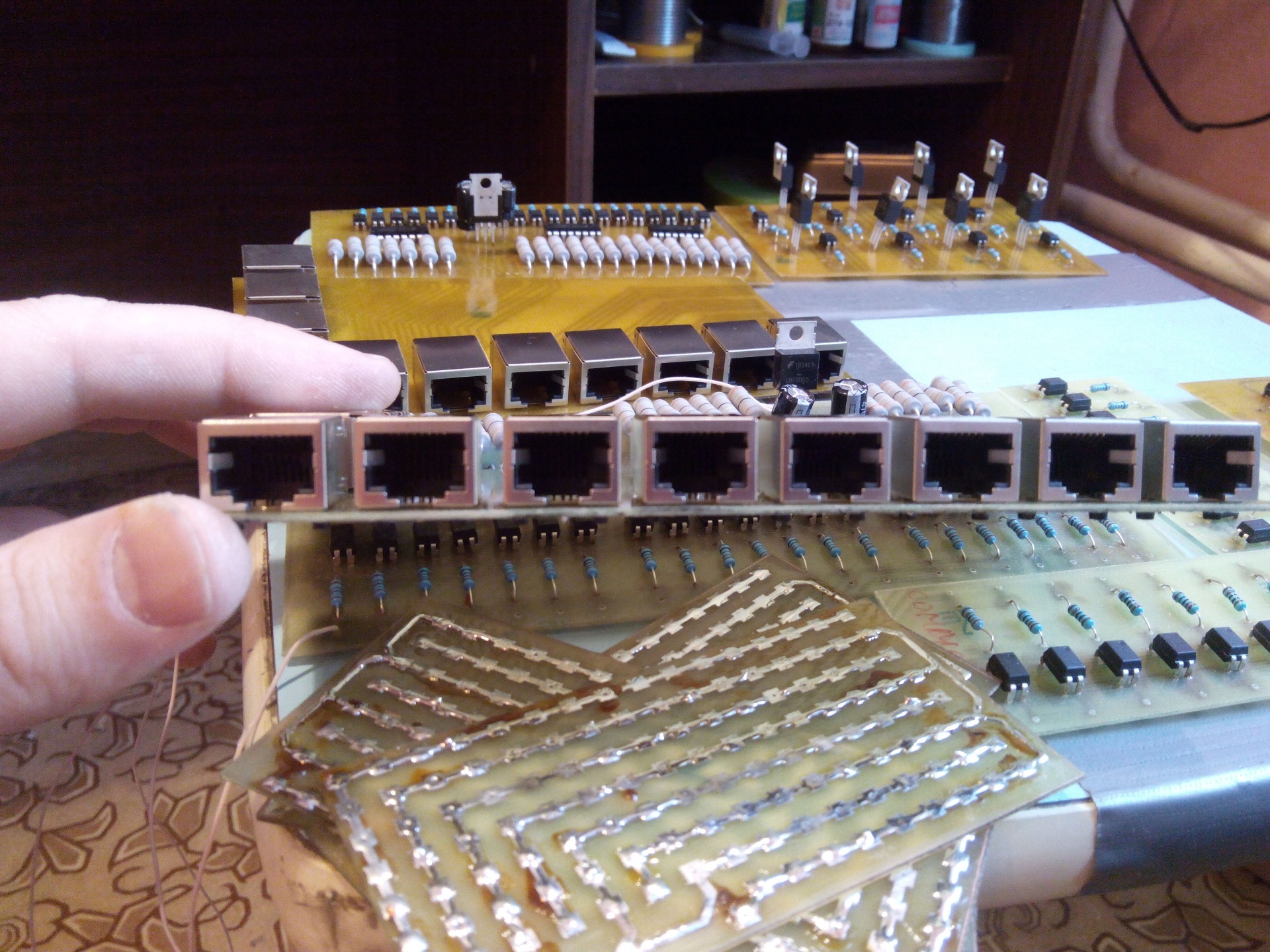
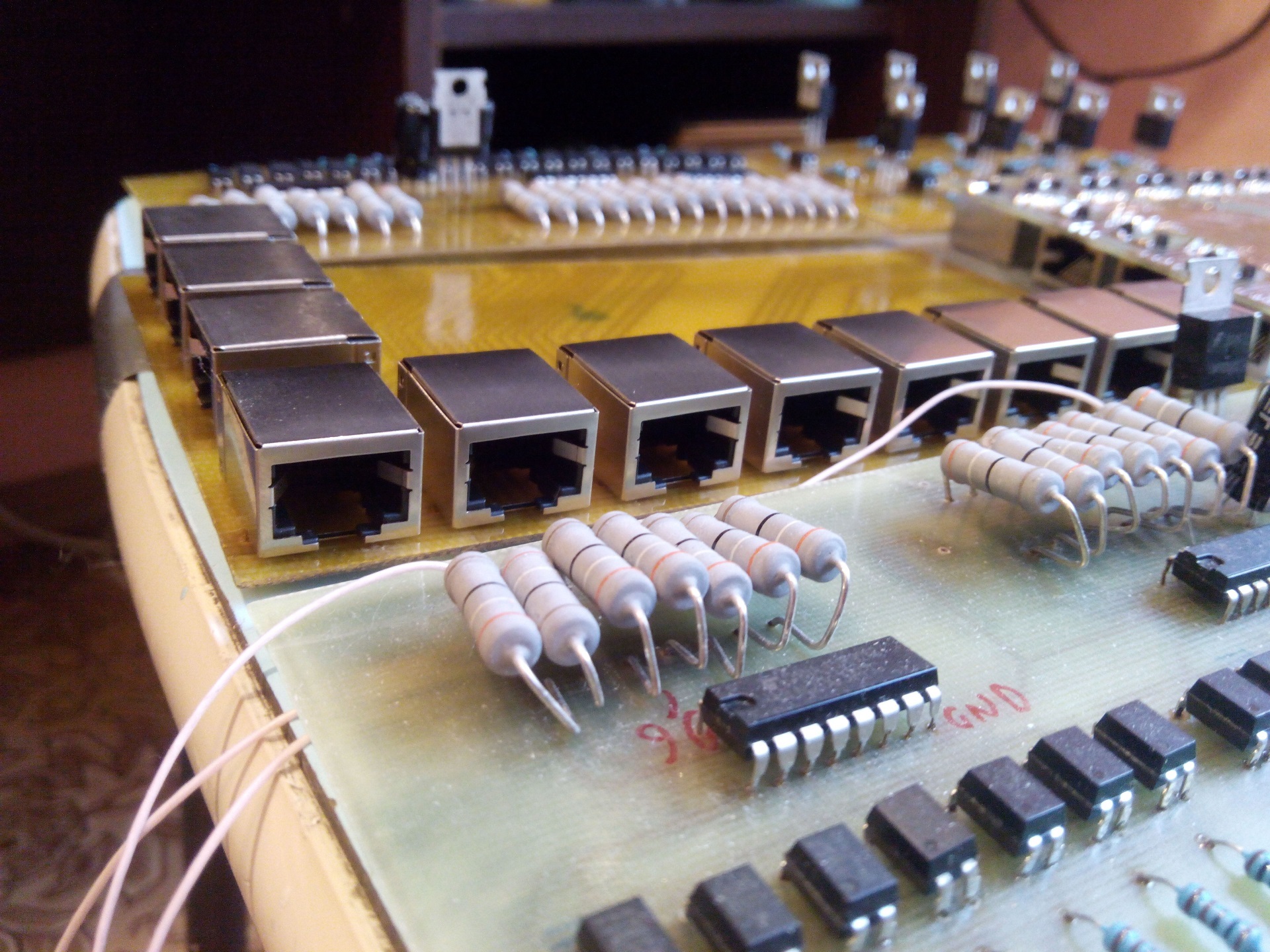
To cross-connect the connections of devices that are located within the locations of the quest and the automation board, I manufactured the following switching modules:

Also in the quest for a number of technical reasons there are a bunch of puzzles, implemented as independent devices, controlled by I2C with MK -1. I made all the electronic modules used in the quest using LUT, DipTrace and some patience. In fact, there was a lot of work on the manufacture of the devices themselves, the cross-connection of sensors and devices among themselves, but I plan to write about this in separate and more detailed articles, each of which will be with a certain thematic “bias” (RFID, I2C, UART, Arduino) .
The power supply of the electronics is carried out using 7 power supply units: 3 power supply units (400 W, 12 V) for powering the low point and LED strips, electric motors and electromagnetic locks; 2 power supply units (400 W, 12 V) for powering car bass amplifiers; as well as an ATX power supply for a PC with a capacity of 600 W for powering all the logic connected by a common point on GND; 1 power supply unit of 24 volts of the OVEN firm, for power supply of solenoids of pneumatic cylinders.
Also in the implementation of independent, but slave MK - 1 devices, electronic items such as RFID - modules MRFC - 522 in the amount of 8 pieces, Chinese lasers with a wavelength of 650 nm were used.
And finally, quite an interesting moment in the whole system: this is a quest management. Despite all our efforts, to simplify wherever it was possible, the quest turned out to be a complex electro-mechanical organism, which requires an accessible, convenient and inexpensive platform to manage. I had to see quest rooms, where the control of the game mode and the service part was carried out using automatic machines and switches. On this occasion, I would like to say that in this case the need for a complex automation system disappears altogether, for it is easier to hire a former civil aviation pilot to work as a quest operator, since only he will be able to control the work of five dozen actuators and hundreds of sensors and sensors. As I already mentioned, this quest in my biography of the “electronics developer for the questroom” is the fifth in a row, and in 3 other questrooms I use a control system built on a web server that runs on the quest's PC. In the specific case, its capabilities were not enough, since the service mode for the described system involves the work of the quest personnel inside the location and rooms of the quest (in the service mode, devices working in the quest are configured, everything is set to default, the initial state is closed, all locks are checked health of the mechanic, monitors the performance of sensors and sensors). Therefore, the decision to manage the quest using the tablet was not accidental. And in this case, I was very helped by talented guys-programmers from St. Petersburg. The guys are developing the free application “DK Gadget” for Android, which allows you to control various devices using Bluetooth, Internet, Wi-Fi. The application is incredibly convenient and has a fairly rich functionality for implementing the most daring ideas on managing various electronics based on Arduino, Raspberry Pi, etc. I am sure that many will be able to use it in their projects. The program allows you to control the state of puzzles and devices, as well as receive service data about the states of sensors, sensors and other necessary information in your widgets. All quest management takes place using an Android tablet using the application described. I hope to also write a separate article describing the capabilities and functionality of the application, as well as describe the work of the libraries for Arduino, with the help of which the data exchange between the tablet and the device is implemented.
Well, the most “exotic part” of automation for the quest is the kinematics of animatronic , this insane monstrous monster, designed to frighten in the darkness unsuspecting players passing the quest. To implement the animatronic, we needed to manufacture pneumatic actuators on Camozzi pneumatic cylinders with a piston diameter of 20 mm and a piston rod stroke of 150 mm. The entire pneumatic system, including air preparation, was assembled on the plywood board. The operation of pneumatic cylinders is fueled by bistable pneumatic distributors, controlled by solenoids with a power supply of 24 volts. Here the driver assembled on the assembly of Darlington transistors ULN2003A helped us a lot. It does not make sense to talk about this chip, since it is the most popular driver of loads up to 500 milliamperes per channel, controlled by voltages of 3.3 and 5 volts. The driver is controlled by Arduino Uno with a very simple code. Since the pneumatic distributors are bistable, the control comes down to opening / closing the valve at the right moment.
Here are the promised photos, which unfortunately are still not enough.
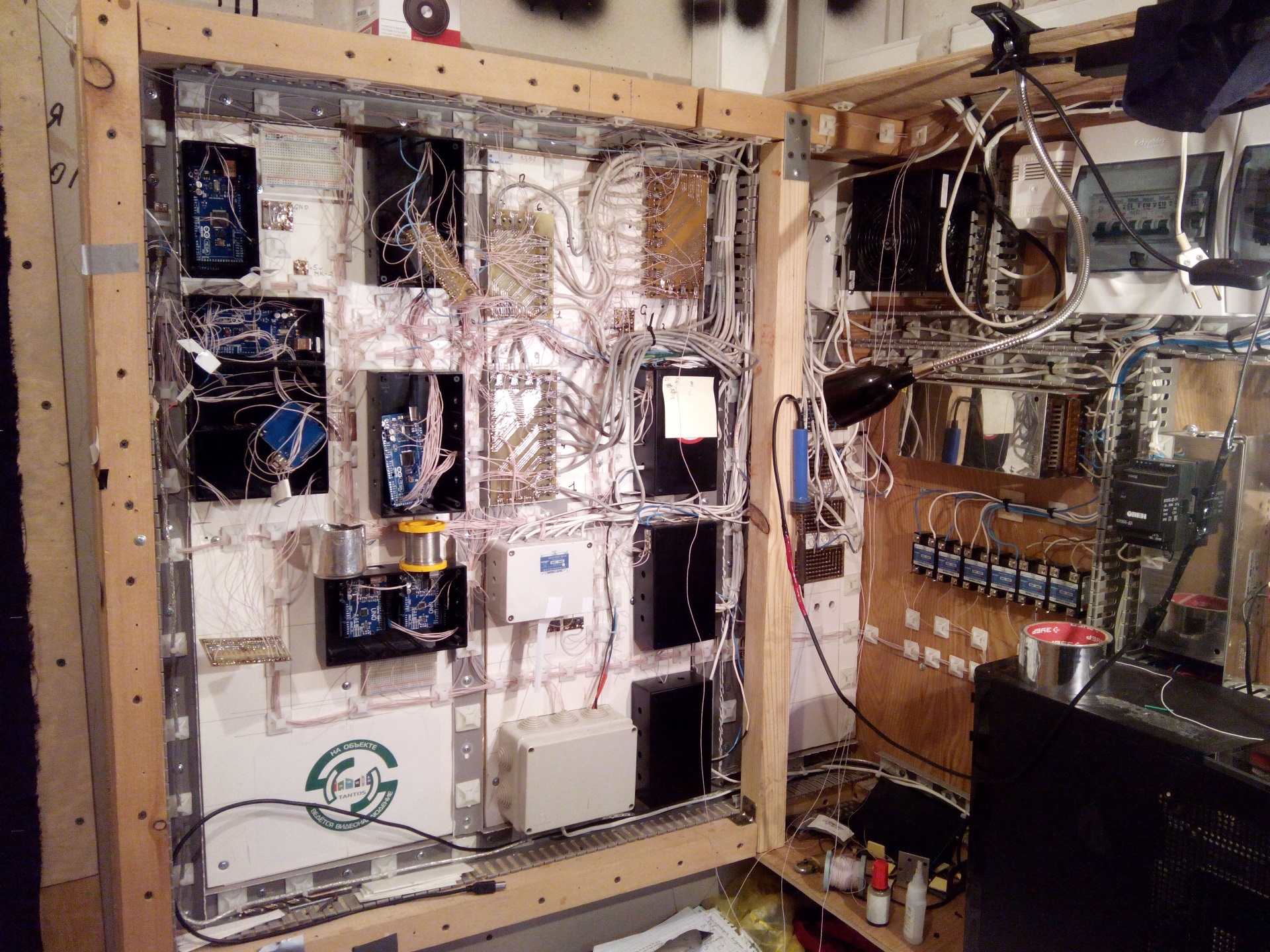
Automation shield during assembly:
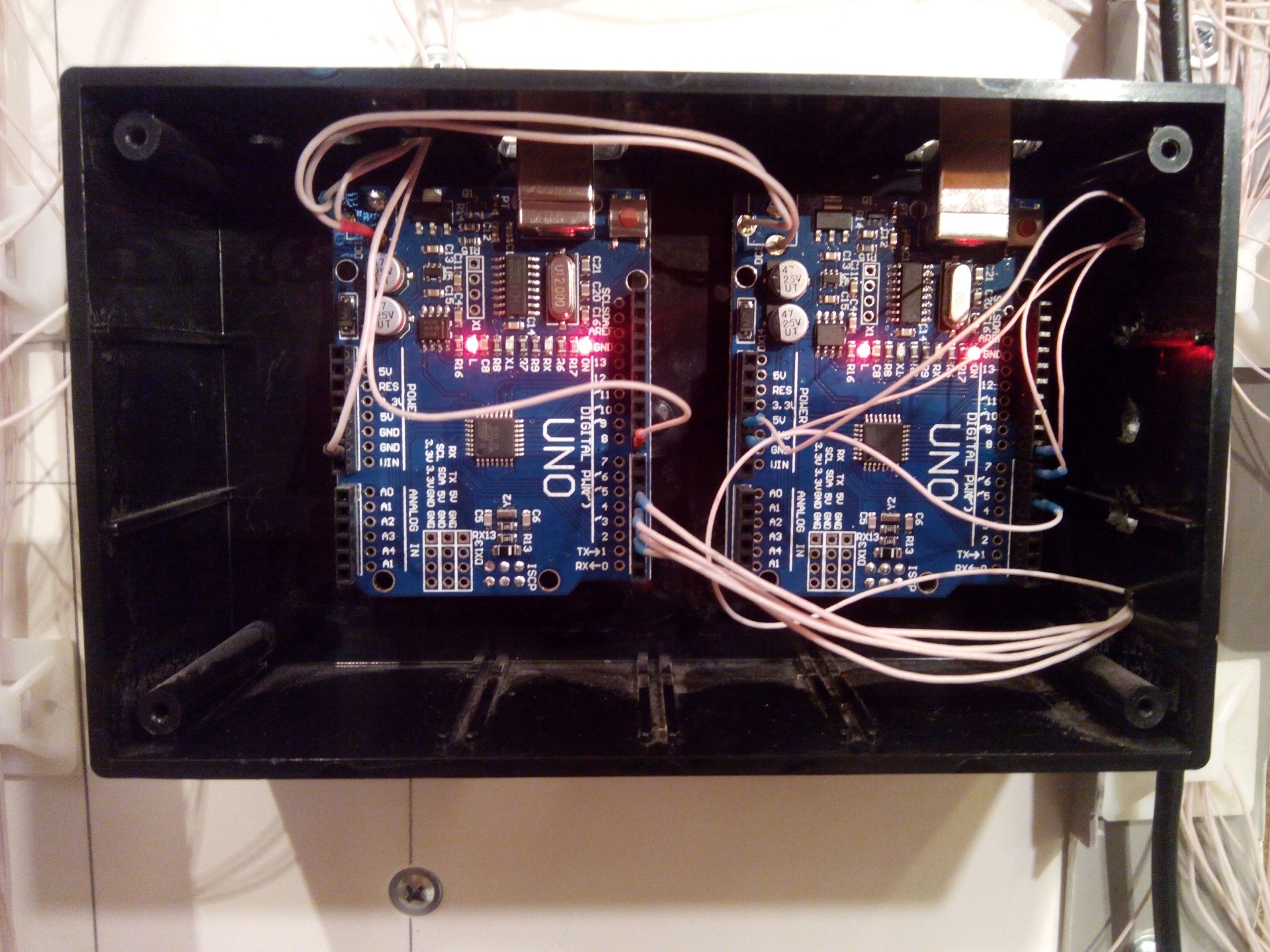
One of the electronics units with controllers:
Part of the module boards before installing them in the automation panel and in the blocks:

That's all for now. In fact, this article would very much like to open a whole cycle of publications devoted to “DIY-technologies”, in which I would very much like to tell you in detail about various “interesting things” and share experiences, since there are plenty of bumps in this matter. I count on interesting and entertaining comments and thank you all for your time.
The idea of writing this article was born quite a long time ago: the development and implementation of electronics and automation for 5 questrooms is behind us. Communication with colleagues in the shop showed that many of them use simpler solutions and much more serious solutions when building quests. Since I do not pretend to a certain competence or authority in the development of electronics, this article makes sense to transfer experience, and is an attempt to talk about my own vision of the use of automation of the type "DIY" in the field of entertainment.
So, let's begin. For those who do not know, “quests in reality” is a type of modern entertainment, where for a certain time a team of players are offered to find a way out of the “custom” location, simultaneously solving various tasks and missions assigned to them. Starting from the room with the door, and a bunch of mechanical code locks, the “quest rooms” evolved into a huge “show monster”, combining elements of theatrical performance, performance, 3-d shows, attractions, etc. Creating such quests requires considerable financial investments and efforts. And now I will tell you how we built a similar quest, without using industrial solutions in automation and ensuring interactivity, because such things would cost in an amount that is an order of magnitude higher than those we spent on building the entire location along with the tweaking of the reception. In order to keep commercial secrets, I will not be able to name either the name of the questroom itself, or the company, or show photos of the implemented puzzles and devices. But still, I can show something, and try to tell everything in as much detail as possible in this article.
First of all, I’ll try to outline the very implementation scheme of the automatic questroom. It consists of such components as:
- implementation of game mechanics (devices, puzzles, sensors, actuators);
- the implementation of interactivity (voice actions of the players in the quest, playing videos, lighting control);
- implementation of the quest management (preparing the quest for work and managing the game and service functions of the electronics);
')
To implement the game mechanics in the role of actuating devices, elements such as electromagnetic and electromechanical locks, electric motors, smoke machines, LED and luminescent lighting, pneumatics, and stepper motors were used. The sources of signals are motion sensors, reed sensors QMS, RFID readers, photo detectors, electro-technical buttons and limit switches, variable resistors, resistive sensors.
All actions and events that occur during the game in the quest are voiced, just as it happens in any video game. The interactivity of what is happening is implemented in the format: PC, to which 2 class AB + 6 car speakers are connected, giving a total power peak of 800 watts. Also, 2 LCD monitors are connected to a PC running the good old Win7, which play video clips at certain game moments, and at some other time display some static screens. And oddly enough, the whole kitchen works and is controlled by an AVR Atmega 2560 microcontroller, carefully soldered to the ** Arduino Mega 2560 board ** by our friends from a nearby but well-known state. But first things first. In total, the quest uses the following electronics and automation:
- 6 motion sensors;
- 15 reed sensors QMS;
- 4 resistive sensors made of foil textolite;
- 3 electric motors from the glass-lifting mechanism of cars;
- 1 smoke machine;
- 1 compressor with receiver for pneumatic operation;
- 2 Camozzi pneumatic cylinders + all strapping for air preparation and control;
- 23 buttons to enter codes in the keypad puzzles with the input code;
- ultrasonic distance measuring sensor HC-SR04;
- noise sensor for Arduino on a condenser microphone with a comparator;
- asynchronous three-phase brushless motor 380 V;
- about 50 meters of LED strips;
- 33 LEDs 1 Watt;
- 4 10 Watt LEDs to illuminate the room in the lamps;
- 3 LED lights;
- 15 Arduino boards (Uno, Mega 2560, and Pro Mini);
- 16 boards of modules, manufactured and developed independently for this quest;
- 2500 meters of cable UTP Cat-5e, SHVVP and PUGNP;
- 1000 meters of MGTF cable for cross-connecting electronics and modules with each other;
- 2 car amplifiers with a total capacity of 800 watts;
- 6 car coaxial speakers, each with a peak power of 120 watts;
- 2 three-phase contactor 5 Ampere;
- 8 solid-state relays with a load capacity of 25 Amps;
- 1 PC (x64) based on Windows 7;
- and a bunch of different uninteresting, but necessary little things.
For a start: about interactivity. All events and actions of players inside the quest are voiced (opening doors, penetrating rooms, working out sensors and sensors, and other game moments are all voiced, while playing the game also plays audio scenes). The game has dynamically played music: about 40 audio tracks are played in certain game moments and events, each audio track smoothly converges with the previous one. In total, about 100 event sounds and about 40 background music audio tracks are used in the quest. There are also two LCD monitors on the quest, on which, before performing a certain action, the players hang a static JPEG background, which smoothly changes to a video that is also triggered by an event. All these charms of multimedia technology were realized with the help of an ordinary office PC, with a video card that supports output to 2 monitors, and a special program, written at my request by one talented programmer. The program itself acts as a multimedia player with some features that are inaccessible to all household Aimps and Winamps. Namely, launching an arbitrary audio or video file with settable parameters, such as the volume level and fading characteristics. The program is controlled by commands received from the head controller (Arduino Mega 2560) via UART .
The head controller performs a variety of functions:
- it runs the code of the program "game engine", which controls all the functions of automation and electronics of the quest;
- it receives signals from input devices (sensors, sensors, devices) through several “input modules” in the form of logic levels 0 and 1 to their GPIO ports;
- it sends commands to the PC to control the “media player” via the UART-0;
- it communicates with other controllers on I2C;
- it carries out reception / transmission of data to the tablet via Bluetooth (on the HC-06 module connected to the UART - 1), where the tablet is a quest control and monitoring device;
As mentioned above, the head controller (let's call it MK - 1) exchanges with other system controllers using the TWI (I2C) bus, which perform various tasks. The second most important controller (MK - 2) controls the output devices (electromagnetic locks, LED dimmers, electric motors, etc.) with the help of self-made "output modules". For this quest, I made several different input / output modules.
Circuitry is quite simple: galvanic isolation on the PC-817 optocoupler, n-channel MOSFET - transistors to control LEDs, electromagnetic locks + diode connected in parallel to the output to eliminate EMF self-induction of electromagnetic locks, electrotechnical relays to control powerful low-voltage loads (electric motors from windows, an injector insome "Mark II", these motors have a strong starting current up to 20 Amps, and a working current in the area from 3 to 7 Amps, but there are a huge number in the "demolition" for ridiculous not from 200 rubles). And finally, a number of high-voltage loads (smoke - machine, power units of remote devices, asynchronous three-phase motor, ultraviolet illumination of 220 V) is controlled using solid-state relays for a load current of 25 Amps, directly from the output of the MK-2 controller, which is responsible for controlling output devices.
To cross-connect the connections of devices that are located within the locations of the quest and the automation board, I manufactured the following switching modules:
Also in the quest for a number of technical reasons there are a bunch of puzzles, implemented as independent devices, controlled by I2C with MK -1. I made all the electronic modules used in the quest using LUT, DipTrace and some patience. In fact, there was a lot of work on the manufacture of the devices themselves, the cross-connection of sensors and devices among themselves, but I plan to write about this in separate and more detailed articles, each of which will be with a certain thematic “bias” (RFID, I2C, UART, Arduino) .
The power supply of the electronics is carried out using 7 power supply units: 3 power supply units (400 W, 12 V) for powering the low point and LED strips, electric motors and electromagnetic locks; 2 power supply units (400 W, 12 V) for powering car bass amplifiers; as well as an ATX power supply for a PC with a capacity of 600 W for powering all the logic connected by a common point on GND; 1 power supply unit of 24 volts of the OVEN firm, for power supply of solenoids of pneumatic cylinders.
Also in the implementation of independent, but slave MK - 1 devices, electronic items such as RFID - modules MRFC - 522 in the amount of 8 pieces, Chinese lasers with a wavelength of 650 nm were used.
And finally, quite an interesting moment in the whole system: this is a quest management. Despite all our efforts, to simplify wherever it was possible, the quest turned out to be a complex electro-mechanical organism, which requires an accessible, convenient and inexpensive platform to manage. I had to see quest rooms, where the control of the game mode and the service part was carried out using automatic machines and switches. On this occasion, I would like to say that in this case the need for a complex automation system disappears altogether, for it is easier to hire a former civil aviation pilot to work as a quest operator, since only he will be able to control the work of five dozen actuators and hundreds of sensors and sensors. As I already mentioned, this quest in my biography of the “electronics developer for the questroom” is the fifth in a row, and in 3 other questrooms I use a control system built on a web server that runs on the quest's PC. In the specific case, its capabilities were not enough, since the service mode for the described system involves the work of the quest personnel inside the location and rooms of the quest (in the service mode, devices working in the quest are configured, everything is set to default, the initial state is closed, all locks are checked health of the mechanic, monitors the performance of sensors and sensors). Therefore, the decision to manage the quest using the tablet was not accidental. And in this case, I was very helped by talented guys-programmers from St. Petersburg. The guys are developing the free application “DK Gadget” for Android, which allows you to control various devices using Bluetooth, Internet, Wi-Fi. The application is incredibly convenient and has a fairly rich functionality for implementing the most daring ideas on managing various electronics based on Arduino, Raspberry Pi, etc. I am sure that many will be able to use it in their projects. The program allows you to control the state of puzzles and devices, as well as receive service data about the states of sensors, sensors and other necessary information in your widgets. All quest management takes place using an Android tablet using the application described. I hope to also write a separate article describing the capabilities and functionality of the application, as well as describe the work of the libraries for Arduino, with the help of which the data exchange between the tablet and the device is implemented.
Well, the most “exotic part” of automation for the quest is the kinematics of animatronic , this insane monstrous monster, designed to frighten in the darkness unsuspecting players passing the quest. To implement the animatronic, we needed to manufacture pneumatic actuators on Camozzi pneumatic cylinders with a piston diameter of 20 mm and a piston rod stroke of 150 mm. The entire pneumatic system, including air preparation, was assembled on the plywood board. The operation of pneumatic cylinders is fueled by bistable pneumatic distributors, controlled by solenoids with a power supply of 24 volts. Here the driver assembled on the assembly of Darlington transistors ULN2003A helped us a lot. It does not make sense to talk about this chip, since it is the most popular driver of loads up to 500 milliamperes per channel, controlled by voltages of 3.3 and 5 volts. The driver is controlled by Arduino Uno with a very simple code. Since the pneumatic distributors are bistable, the control comes down to opening / closing the valve at the right moment.
Here are the promised photos, which unfortunately are still not enough.
Automation shield during assembly:
One of the electronics units with controllers:
Part of the module boards before installing them in the automation panel and in the blocks:
That's all for now. In fact, this article would very much like to open a whole cycle of publications devoted to “DIY-technologies”, in which I would very much like to tell you in detail about various “interesting things” and share experiences, since there are plenty of bumps in this matter. I count on interesting and entertaining comments and thank you all for your time.
Source: https://habr.com/ru/post/396483/
All Articles