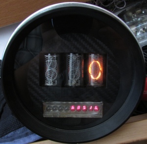
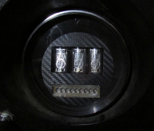
Speedometer / odometer on IN14
Good day!
Once again, creativity attacked. I decided to update the old speedometer in the battle tank VAZ 2121. Having made a revision of the bins, I found 3 pieces of IN14. For hours - a little, for a thermometer - a lot. Neither there - nor here. In the speedometer - the most it.
For a start, the standard speedometer was removed and gutted. The current mileage is saved on a piece of paper, so that everything is fair. The speed sensor was acquired 10 pulses per revolution (DSA-3). As indicators of speed — the aforementioned IN14, for displaying run, hours and other things — widely known in narrow circles of the Caller ID on z80 - ALS318.

Initially, the PIC18F452 was chosen as the core of the device for the abundance of GPIO. Then I got an i2c port extender mcp23017, which I have long wanted to get to. With it, the need for a lot of GPIO disappeared, and was chosen close to me in the latest designs, msp430g2452. Also found RTC - i2c watch ds1307.
IN14 requires 170 volts for normal operation. Boost DC-DC was assembled according to a proven scheme on the MC34063 + IRF740. I will describe some of the nuances that appeared in the process of creation.
1. Round case . Not very convenient form for placement inside the electronics and display. I had to make the internal design of a modular with multiple connectors. The task was also to make the hull airtight (or almost sealed), as the waterline in connection with the operating conditions of the vehicle is above the roof. This was decided by pouring extra holes with epoxy glue and installing a single connector to communicate with the outside world. Actually design:

and connector:

2. Dynamic indication . In order not to notice the switching of digits during dynamic display, so infuriating certain people, the update rate of each digit should be at least 100 Hz. True, there are those who see 100 Hz, but I do not ride them on this car. Of the two indicators, the most difficult from this point of view is the 9-bit ALS318. It turns out that the frequency of updating the readings should be at least 9 * 100 Hz. To simplify the calculation of the intervals - the update frequency of 1kHz was chosen. Circuitry ALS318 is connected to the port extender mcp23017. Port A - segments, port B - discharges. The 9th digit is controlled directly from the GPIO microcontroller. It turns out that once a millisecond, i2c needs to update the state of ports A and B of the expander. From here came out the next nuance.
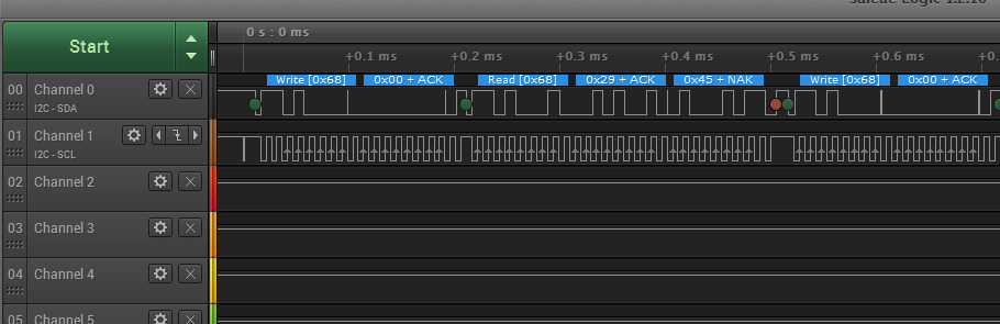
3. Slow exchange on i2c from ds1307 . In our case, two slaves hang on the i2c bus. Port Expander and Clock. The latter do not keep up with the SCL frequency above 100kHz, while the extender can operate at frequencies up to 1.7 MHz. To update the ports of the expander, it is necessary to write to i2c once in 1 ms 4 8-Mbit words (the address of the expander, the address of port A, the data for port A, the data for port B). During the initialization, the expander is programmed to autoincrement the addresses of the internal registers during reading / writing. And the port B address immediately follows the port A address, which saves on the transmission of the additional port address B. To ensure a short processing time of the display update procedure, the clocking frequency SCL - 500 kHz was chosen. Moreover, the clock status is polled once per 100 indication update cycles, i.e. once in 100ms The clock polling procedure sets the SCL frequency to 100kHz permissible for ds1307. When debugging the i2c exchange, the SaleaeLogic USB logic analyzer (8 channels, up to 24 MHz sampling) helped a lot. Soft to it can decode various protocols, including i2c.
4. Power . The speedometer for storing time is continuously powered from the battery and for work - the voltage applied when the ignition is turned on. The DC-DC converter and decoder for IN14, the port expander are powered last. In the absence of ignition voltage - the device is transferred to the storage mode. If the ignition key is on, the display starts, and the interrupts from the speed sensor are enabled. When the ignition is turned off - odometer readings are recorded in the non-volatile memory of the microcontroller.
5. Management To set the clock, reset odometer readings (there are two, except for the main odometer), an encoder with a button is used (the picture honestly plucked in the network. Your encoder is already filled with hot-melt adhesive for waterproofing):

6. Logic levels of i2c slaves . Since the ds1307 clock is powered by 5V, and the microcontroller and the port expander from 3.3V - pull-up resistors of the i2c bus are connected to 3.3V. According to ds1307, the voltage of a logical unit is 2.2V, then 3.3V will be completely normal.
7. Watchdog The system uses hardware i2c interface, while waiting for sending / receiving bytes the processor is “asleep”. In case of failure / disconnection of the ignition at this time - the microcontroller may not wait for the slave’s response and remain in “sleep” mode. To eliminate such hangs, the hardware watchdog of the microcontroller is used. In the main loop, the watchdog is constantly reset. In the event of a hangup, the main loop stops and the watchdog overflows, sending a reset to the microcontroller. To determine the nature of the reset (power on or watchdog), a variable is entered into the program that is not initialized during a reset (#pragma NOINIT). If it is equal to the known value, there was a reset by watchdog.
8. Calibration In principle, calibration can be done already in battle, for example, go at a certain speed over gps. Typing, for example, 30 km / h - click on the mouthguard, and the speedometer will memorize the measured frequency of the pulses, corresponding to 30 km / h. But on the back wall there was an interesting inscription:

Thus 10 pulses of the speed sensor will correspond to one meter traveled by the car. If there are significant differences in fact - I will make the necessary adjustments.
9. Vibration resistance. The device is intended for operation in conditions difficult from the point of view of vibration. On the Internet, I did not find information about the vibration resistance of IN14. Time, as they say, will tell. Electrical connections are made by the good old MGTF. After checking the modules - they were filled with epoxy glue. By the way, I found in fixprice quite a glue in the double syringe form factor.
Here are the design elements:


10. Miscellaneous. Existing mileage saved previously with the above mentioned papers in non-volatile memory. Speaking of her. In msp430, nonvolatile memory is organized page by page. For the user, the first three are available. The fourth one stores the calibration data of the clock generator. Saving the readings of the main run meter and two additional reset odometers is done sequentially, filling in alternately the first three pages of flash. When the end of the third page is reached - the first three pages are erased and the recording starts again from the beginning of the first one. Thus, the flash resource increases, although the ignition lock resource (saving occurs when the ignition is turned off) is, of course, less than the resource of erasing the flash record.
In the instrument panel:
In principle, everything. Waiting for comments and comments. Archive with source code and the scheme in diptrace
Unfortunately, the updated habrastorage recognizes the archive in the picture and does not allow it to be saved, so here’s the source code and the schema:
dl.dropboxusercontent.com/u/974924/nivaCon2.rar
PS And yes, these IN14 lamps are really 44 years old.
PPS Video on the move could not be removed. Not enough hands. Determining the speed checked by GPS. Deviations ± 4 km / h at a speed of 40km / h. Adequate accuracy.
Here's a video:
Filmed like this:

')
Source: https://habr.com/ru/post/396433/
All Articles