IoT hub on Intel Edison
Hi GT!
If you would like to make your own "iron" module on Intel Edison, but are not sure which side to approach it - this text is for you. It is about the features and small nuances of creating your device on Edison, without using ready-made debug boards from Intel or Sparkfun.
We recently had a specific task: we needed an IoT hub (that is, a gateway between the Internet of Things specific 6LoWPAN and LoRa networks we are working with and the outside world) on the x86 architecture. Our standard version is a solution on our own Unwired One microcomputer on the MIPS architecture, but in this case it was x86 that was needed.
')
The fact is that our hub is not just a translator from 6LoWPAN / LoRa to the outside world of everything that came from the other side, but first, a small IoT network server that supports its existence distributes IP addresses ( availability of such networks in this network) and is engaged in other technical work, secondly, the border router from IoT itself to the outside world, and thirdly, the application-level layer, which turns our own IoT network protocols into the common MQTT and unifies different types of networks, and fourthly, the platform on which the client can write how Interesting software that accumulates and processes data before sending it to a large server, to the cloud, etc.
Actually, in the latter there was a snag. The problem is that with all the talk about the upcoming victory of IoT, with software at this level, everything is pretty bad in it - it is, to put it briefly, not. Standard, universal, not tied to a specific piece of hardware and not written in Java (forgive me, its fans, but when you have 256 MB of RAM, this is a lot, Java is a so-so choice).
And here we met with Mail.ru DBMS Tarantool. Light - works on devices with 128 MB of RAM. Universal - not tied to a specific Vendor gland or specific Vendor clouds. With built-in application server - and Lua scripting language.
One problem - Tarantool does not work on MIPS, 64 MB of memory is not enough for him, and he also wants FPU, which we also do not have. The second problem - embedded computers on ARM, on which Tarantool works in principle, are very rarely found in dimensions less than 50x50 mm. And if for industrial projects this is often indifferent, then for our set of rapid prototyping of the Unwired Kit, I really would not want to go beyond the width of the base module — 45 mm — without good reason. In addition, the built-in Wi-Fi is a separate rarity, and if we are talking about a prototyping kit, then in nine out of ten it is used with Wi-Fi.
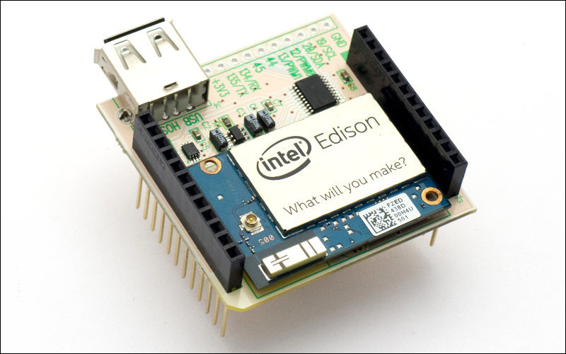
Fortunately, there is a module on the market that fits perfectly with our requirements - very small, with Wi-Fi and not at MIPS.
This is obviously Intel Edison.

Left Unwired One, right - Edison.
Therefore, we took - and made the module UMDK-EDISON, that is, an adapter with Intel Edison with its specific connector to the format of our modules.
And following the results we decided to write about the main difficulties and features of Edison, which should be taken into account if you plan to do the same for your project.
The main problem of Edison is the connector . It uses a high-density interboard connector with an unpleasantly small foot step - 0.4 mm; the width of one leg is 0.2 mm, the gap between the legs is 0.2 mm. On the one hand, if it does not exclude any LUT, then it makes it rather difficult; on the other hand, such dimensions are still within the bounds of the category of complexity in the domestic classification - that is, the same Resonit will make such boards quickly and at basic rates.
Soldering is a little more difficult - but it can also be solved. We tied the connectors to the test samples using the “combined method” - we walked the tracks, applied good flux (EFD SolderPlus NCLR-A) over the top, stuck the connector and put it in the solder paste stove, after the stove we adjusted it with a thin sting and braid to remove the jumpers between the legs. I think that a good thin “microwave” can be soldered completely manually, but for any mass production, of course, you need to make a normal stencil and put a connector on the paste.
The most inconvenient in the connector is that it does not have any pegs for precise positioning in the board - it is obviously intended only for automatic installation. Therefore, it is necessary to set and align carefully.
The connector is made by Hirose and it is called DF40C (2.0) -70DS-0.4V (51). We bought them in " Elitan " - it turned out 60 rubles each piece with delivery in about a month. Nobody has such exotics in warehouses in Russia, but if the current terms and prices of “Elitan” are not satisfied, you can try “ Contest ”, “ Workl ” and other companies that bring the components to order.
But after you dealt with the connector, the Edison connection is extremely simple:
That is, speaking even shorter, it is enough to apply food.
If you want more, then first of all you should pay attention to:
PS And, of course, on the IoT-hackathon in Mail.Ru next weekend, the teams will have this bundle on their hands - Intel Edison, our 6LoWPAN modules and the Tarantool DBMS.
If you would like to make your own "iron" module on Intel Edison, but are not sure which side to approach it - this text is for you. It is about the features and small nuances of creating your device on Edison, without using ready-made debug boards from Intel or Sparkfun.
We recently had a specific task: we needed an IoT hub (that is, a gateway between the Internet of Things specific 6LoWPAN and LoRa networks we are working with and the outside world) on the x86 architecture. Our standard version is a solution on our own Unwired One microcomputer on the MIPS architecture, but in this case it was x86 that was needed.
')
The fact is that our hub is not just a translator from 6LoWPAN / LoRa to the outside world of everything that came from the other side, but first, a small IoT network server that supports its existence distributes IP addresses ( availability of such networks in this network) and is engaged in other technical work, secondly, the border router from IoT itself to the outside world, and thirdly, the application-level layer, which turns our own IoT network protocols into the common MQTT and unifies different types of networks, and fourthly, the platform on which the client can write how Interesting software that accumulates and processes data before sending it to a large server, to the cloud, etc.
Actually, in the latter there was a snag. The problem is that with all the talk about the upcoming victory of IoT, with software at this level, everything is pretty bad in it - it is, to put it briefly, not. Standard, universal, not tied to a specific piece of hardware and not written in Java (forgive me, its fans, but when you have 256 MB of RAM, this is a lot, Java is a so-so choice).
And here we met with Mail.ru DBMS Tarantool. Light - works on devices with 128 MB of RAM. Universal - not tied to a specific Vendor gland or specific Vendor clouds. With built-in application server - and Lua scripting language.
One problem - Tarantool does not work on MIPS, 64 MB of memory is not enough for him, and he also wants FPU, which we also do not have. The second problem - embedded computers on ARM, on which Tarantool works in principle, are very rarely found in dimensions less than 50x50 mm. And if for industrial projects this is often indifferent, then for our set of rapid prototyping of the Unwired Kit, I really would not want to go beyond the width of the base module — 45 mm — without good reason. In addition, the built-in Wi-Fi is a separate rarity, and if we are talking about a prototyping kit, then in nine out of ten it is used with Wi-Fi.
Fortunately, there is a module on the market that fits perfectly with our requirements - very small, with Wi-Fi and not at MIPS.
This is obviously Intel Edison.
Left Unwired One, right - Edison.
Therefore, we took - and made the module UMDK-EDISON, that is, an adapter with Intel Edison with its specific connector to the format of our modules.
And following the results we decided to write about the main difficulties and features of Edison, which should be taken into account if you plan to do the same for your project.
Features and difficulties
The main problem of Edison is the connector . It uses a high-density interboard connector with an unpleasantly small foot step - 0.4 mm; the width of one leg is 0.2 mm, the gap between the legs is 0.2 mm. On the one hand, if it does not exclude any LUT, then it makes it rather difficult; on the other hand, such dimensions are still within the bounds of the category of complexity in the domestic classification - that is, the same Resonit will make such boards quickly and at basic rates.
Soldering is a little more difficult - but it can also be solved. We tied the connectors to the test samples using the “combined method” - we walked the tracks, applied good flux (EFD SolderPlus NCLR-A) over the top, stuck the connector and put it in the solder paste stove, after the stove we adjusted it with a thin sting and braid to remove the jumpers between the legs. I think that a good thin “microwave” can be soldered completely manually, but for any mass production, of course, you need to make a normal stencil and put a connector on the paste.
The most inconvenient in the connector is that it does not have any pegs for precise positioning in the board - it is obviously intended only for automatic installation. Therefore, it is necessary to set and align carefully.
The connector is made by Hirose and it is called DF40C (2.0) -70DS-0.4V (51). We bought them in " Elitan " - it turned out 60 rubles each piece with delivery in about a month. Nobody has such exotics in warehouses in Russia, but if the current terms and prices of “Elitan” are not satisfied, you can try “ Contest ”, “ Workl ” and other companies that bring the components to order.
Circuitry
But after you dealt with the connector, the Edison connection is extremely simple:
- three VSYS legs and one DCIN file +3.3 V (allowable range - 3.15 ... 4.5 V)
- on the six legs of GND file "land"
- PROFIT !!!
That is, speaking even shorter, it is enough to apply food.
If you want more, then first of all you should pay attention to:
- All GPIOs operate at 1.8 V levels, so level adapters are required for interfacing with 3.3 V or 5 V electronics. We use TI TXB series as level converters. Work like a clock, although, of course, there are many alternatives.
- The voltage of 1.8 V for these adapters can be taken from the VDD1V8 foot, an external stabilizer is not needed
- If you do not power the Edison from exactly 3.3 V, but for example, simply from a lithium battery bank, then a stabilized 3.3 V to power the periphery can be taken from the legs of the VDD3V3
- In general, you will want to output the UART debug console - these are the legs of the GP130 (RX) and GP131 (TX). Without a console, Edison is pretty helpless — by default, he doesn’t get Wi-Fi, so the console is the only means of accessing inside. The UART must be output via a level converter and / or a bridge to USB (note that there are different bridges: for example, the FT232R can work with 1.8 V levels as native, but the cheaper CP2102 doesn't, it needs an intermediate converter in 3, 3 C)
- The second UART can be taken from GP134 and GP135
- For the USB port, Edison has a power-on signal and a power over-load signal, so it is better to connect the USB through a dedicated switch — for example, MIC2019 . Do not forget about the levels of 1.8 V - the switch must have a level of "1" at the input of EN in the region of 1.5 V and the FAULT output with open drain, which you pull up to VDD1V8 with a resistor; for example, my favorite STMPS21x1 switches will not work with Edison.
- The connector is low - so components on the Edison board are not recommended to be placed at all. However, components with a height of up to 0.5 mm fit - but not anymore. Therefore, the resistors 0603, if necessary, can be installed under Edison, but with capacitors it is necessary to be careful: even 0603 are found and 0.8 mm high.
Bonus track
- Edison Compute Module Hardware Guide - Intel's official document for working with Edison from a developer's point of view.
- Electrical schematic diagram of our adapter for Edison. In fact, this is the minimum with which Edison runs - plus an 8 GPIO level converter (including a debug UART), plus a second UART that goes to our 6LoWPAN radio modem, plus a USB port
- Library with Edison for DipTrace (there are two characters in it: grouping the legs by number and meaning)
PS And, of course, on the IoT-hackathon in Mail.Ru next weekend, the teams will have this bundle on their hands - Intel Edison, our 6LoWPAN modules and the Tarantool DBMS.
Source: https://habr.com/ru/post/396321/
All Articles