Multichannel servo tester with do-it-yourself indicator
Hello!
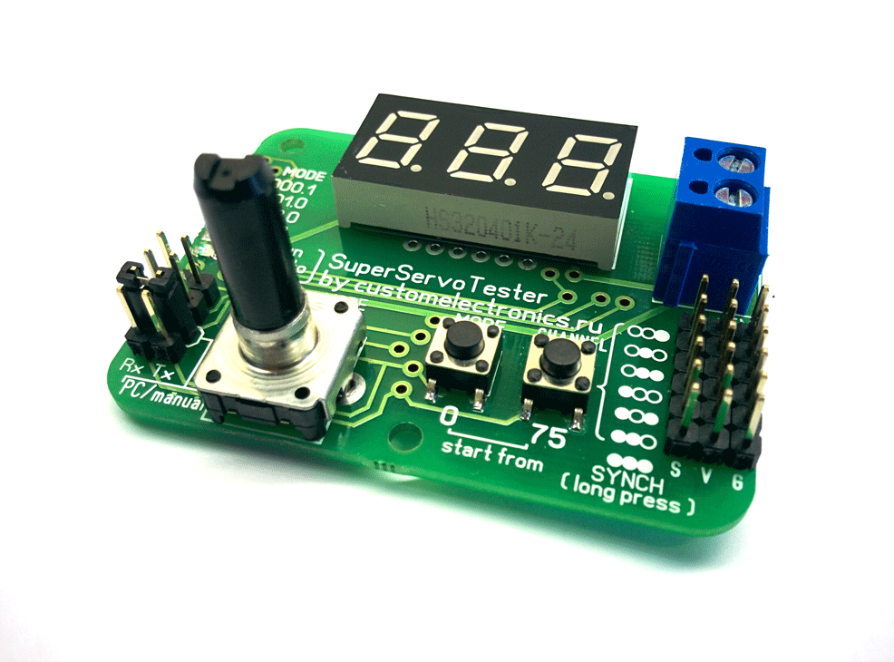
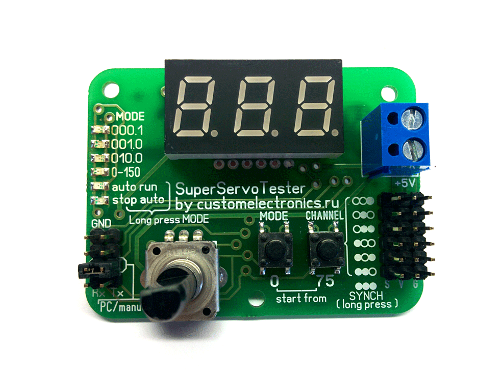
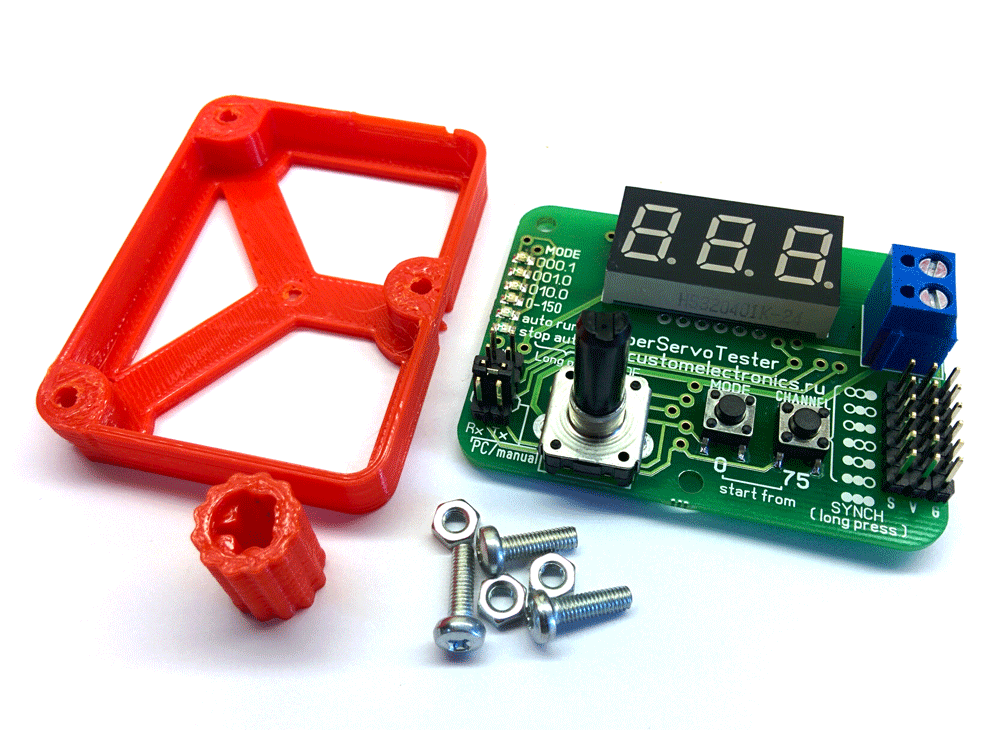
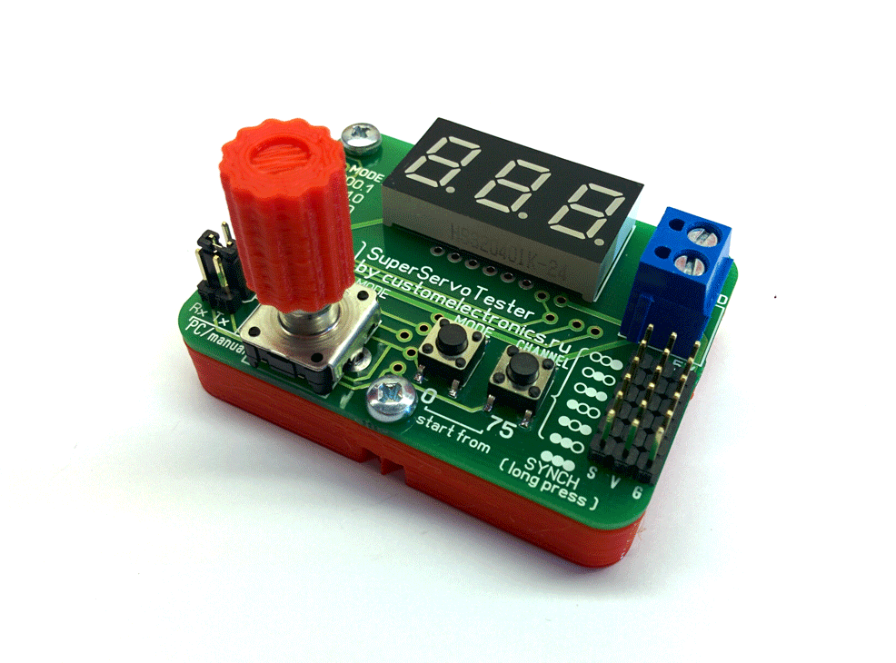
As announced in the previous article about the line , I completed work on the project of a multichannel servo tester and am ready to share all the materials with the community. It can be made at home, but I ordered a batch of boards and now my tester looks like this:
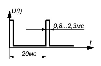
In hobby electronics, systems with control using a PWM signal are widely used. This is a pulse train with a frequency of 50 Hz. The information in them is encoded as a pulse duration, which can vary from 0.8 to 2.3 ms. Extreme values of this range may differ slightly from different manufacturers.
')
Servos for the construction of model aircraft, hexapods, manipulators, etc., use just such a signal. As a rule, they have three wires - power, common and signal. Also in aeromodelling, car modeling, and copter construction, stroke controllers of collector and brushless motors use the same control signal that determines the speed and direction of rotation of the engines.
The source of such a signal can be a control panel, a programmed controller or something like that. But very often at the construction stage it is convenient to use a servo tester that generates the same signal in manual mode. This allows you to check in advance the performance of mechanics, measure the extreme positions, etc.
Most testers that you can buy now are either very simple or expensive. I wanted to make it as cheap as possible, but at the same time give it the widest possible functionality. Here's what I got:
But its characteristics:
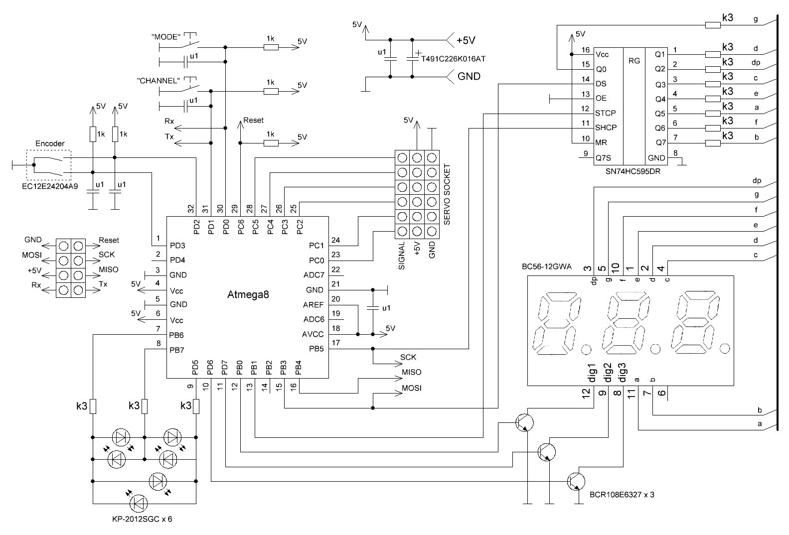
Working on the scheme, I tried to make it as cheap as possible and make it easy to repeat. The Atmega8A-AU controller was used as the control controller.
Three-digit seven-segment dysplay is connected via a shift register and logical transistors. Six LEDs are used to display the current mode and they are connected by the so-called charliplexing method to save the findings of the MC.
For control, the usual incremental encoder and two buttons are used. The encoder controls the set angle, and the buttons switch the control mode and the current channel. Everywhere there are capacitors from the bounce of contacts, so that it all works very well.
Tester connectors are designed to connect the servos themselves, programming, connecting to a PC and power. I decided not to install a power stabilizer on the board. That is, to use it, it will not be possible to use battery voltage directly. It is necessary to find a source or stabilizer on 5V with a current corresponding to the current consumed by the connected motors.
When checking a bunch of brushless motor with speed control (ESC), the engine itself is powered by a battery. If the ESC has a built-in speed controller, you can power the tester directly from it.
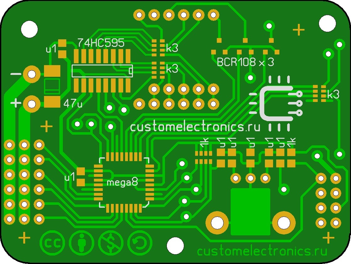
The PCB is prepared in Sprint Layout format. This is a double-sided board, but I drew it in such a way that it could be made at home using LUT or photoresist, and jumpers could be easily soldered to the vias from one side of the board to the other.
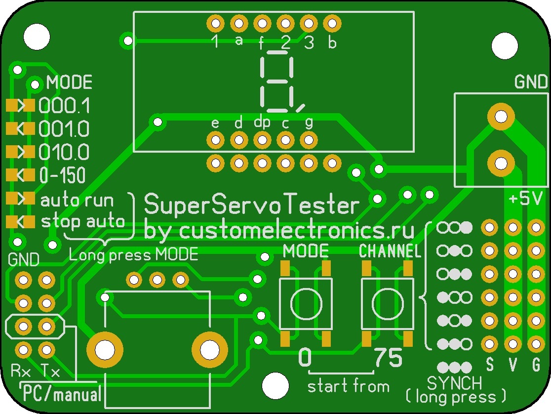
Front side of the board:
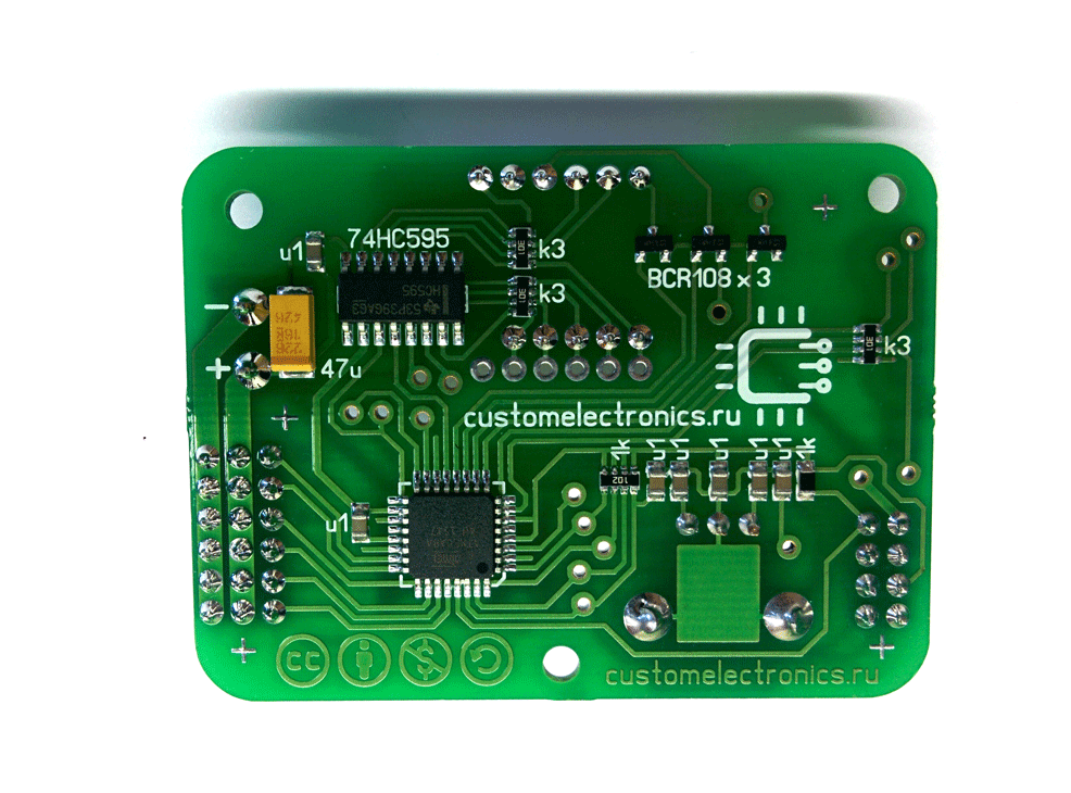
... and reverse:
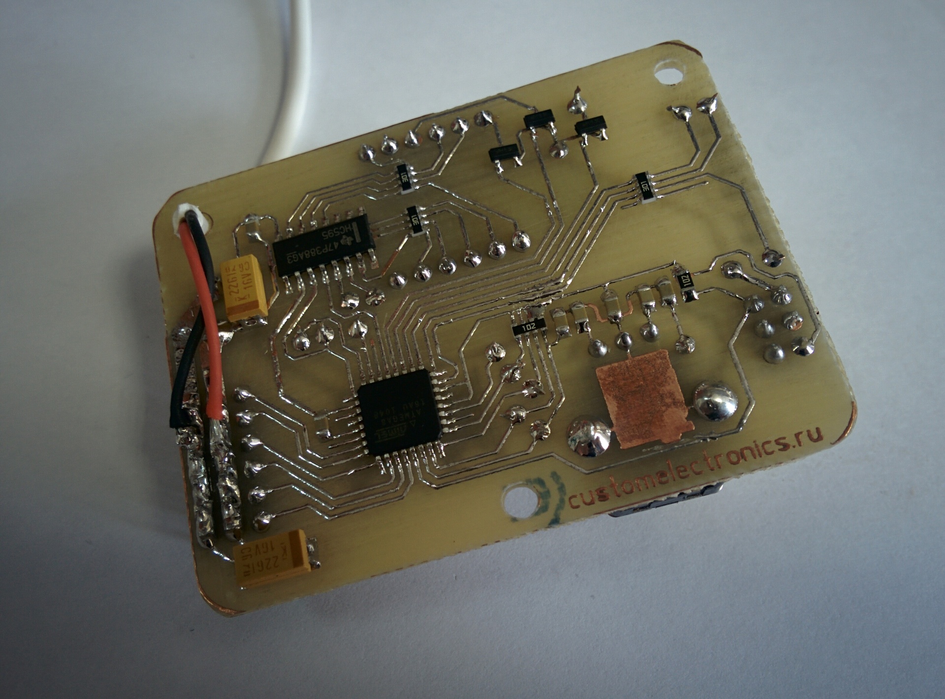
I made this board by hand and I checked everything and it works:
I also conducted a small campaign among community subscribers Goods from China to the radio amateur and our local hackspace MakeItLab and found people who supported the release of a small batch of devices. Taking this opportunity, I want to express my gratitude to them. Here is the device in the factory:
Here is a complete list with links:
I also drew and printed on a 3D printer a small mandrel and a pen on an encoder. Files for download later.
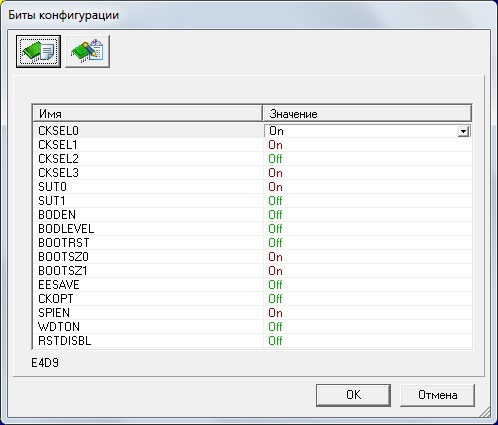
The firmware files will be at the end of the article. You can flash the controller using any ISP programmer through a standard 6-pin connector. On the board, six of the eight contacts to the left of the encoder are intended primarily for this purpose.
You need to install the fusion bits as shown in the figure:
It is easier, of course, to see once:
To start the tester in the manual control mode, it is necessary that the “PC / Manual” jumper at power-up be set.
When launched in manual mode, the “HI” greeting will appear on the display and the tester will go into the mode of waiting for the user to select the initial duration of the signal. Roughly speaking, from the edge or from the middle of the range. When you click on the left button control will occur from zero, when you click on the right - from the middle. After pressing one of the buttons, the generation of the signal will start, the first channel will become active and it will switch to the “1” mode.
In the operating mode, the MODE button switches the control modes, changing the increment step. The current mode is displayed using six LEDs. Four manual modes are possible (step 0.1; 1; 10 and from 0 to 150, that is, between the edges of the ranges) and two automatic modes (start / stop). A long press on the MODE button switches the channel to the automatic control mode and the engine begins to gently swing from side to side. A short press of the MODE button in automatic mode stops or resumes movements. A long press on the MODE button returns the channel to the encoder control mode.
The CHANNEL button toggles between active channels. The current active channel is displayed on the display in binary code using bit points. A long press on this button switches the tester to the formation of identical pulses on all channels.
Note that the indicator displays numbers from 0 to 150. This roughly corresponds to the angle of the servo and can be recalculated into the pulse duration. For recalculation, it is enough to multiply the readings by ten and add 800. For example, if the indicator is ten, then the pulse duration is 900 μs.
If you are using the Raspberry Pi, then you can simply plug in Rx, Tx and GND in the bottom left of the board. If you do not have a TTL-compatible COM-port in your computer, then you can use USB-COM-adapter, which are very cheap. You can also take a 5V USB port, but remember that its maximum current is 500mA! Connection speed - 9600.
In order for the tester to boot into PC control mode, it is necessary to turn it on without a jumper. At the same time, the letters “PC” will be displayed on the indicator and the tester will go into standby mode for commands from the PC. Before the arrival of the first full packet on all channels, the signal will be absent.
Pulse duration values must be sent in microseconds from 0 to 1500. That is, two bytes are consumed for each channel.
The data packet should consist of 16 bytes: first two bytes 0xFF to indicate the beginning of the packet, then 12 bytes of pulse durations for each channel and at the end two bytes of the check sum. The check-sum is necessary to verify the correctness of the package and must be equal to the sum of all durations.
1st byte - 255 (0xFF)
2nd byte - 255 (0xFF)
3rd byte - high byte of the first channel
4th byte - low byte of the first channel
5th byte - high byte of the second channel
6th byte - low byte of the second channel
7th byte - high byte of the third channel
8th byte - low byte of the third channel
9th byte - high byte of the fourth channel
10th byte - low byte of the fourth channel
11th byte - high byte of the fifth channel
12th byte - low byte of the fifth channel
13th byte - high byte of the sixth channel
14th byte - low byte of the sixth channel
15th byte - the high byte of the check-sum
16th byte - low byte check-sums
Examples of valid packages (in decimal):
255 255 0 0 0 0 0 0 0 0 0 0 0 0 0 0 (all engines in the initial position)
255 255 2 238 0 0 0 0 0 0 0 0 0 0 240 (first engine in middle position)
255 255 2 238 2 238 2 238 2 238 2 238 2 238 17 148 (all engines are in the middle position)
Printed circuit board
Firmware
Model to print the case
And, excuse me, the link to the main article on my site .
As announced in the previous article about the line , I completed work on the project of a multichannel servo tester and am ready to share all the materials with the community. It can be made at home, but I ordered a batch of boards and now my tester looks like this:
What is it for
In hobby electronics, systems with control using a PWM signal are widely used. This is a pulse train with a frequency of 50 Hz. The information in them is encoded as a pulse duration, which can vary from 0.8 to 2.3 ms. Extreme values of this range may differ slightly from different manufacturers.
')
Servos for the construction of model aircraft, hexapods, manipulators, etc., use just such a signal. As a rule, they have three wires - power, common and signal. Also in aeromodelling, car modeling, and copter construction, stroke controllers of collector and brushless motors use the same control signal that determines the speed and direction of rotation of the engines.
The source of such a signal can be a control panel, a programmed controller or something like that. But very often at the construction stage it is convenient to use a servo tester that generates the same signal in manual mode. This allows you to check in advance the performance of mechanics, measure the extreme positions, etc.
Features and characteristics of our device
Most testers that you can buy now are either very simple or expensive. I wanted to make it as cheap as possible, but at the same time give it the widest possible functionality. Here's what I got:
- Six independent control channels. It is independent! Usually in ready-made it is possible to connect several engines at the same time, but the signal to them is the same. On my device, you can even start one in automatic mode, and control the rest in manual mode, etc.
- Signal generation and indication in microseconds. In most testers, the display is displayed is not clear what is, or is missing at all
- The minimum step change duration - 1mks. That is, the range of 0.8-2.3 ms is divided into 1500 steps.
- Ability to connect to PC. You can use it, for example, paired with Raspberry Pi. The signal itself will be formed at the same time much more precisely than by means of the single-board computer itself.
- Openness At the end of the article you can find all the files necessary for the self-production of the tester.
But its characteristics:
- Power supply - 5V
- Current consumption (without servo drives), no more - 100mA
- The duration of the generated pulses - 0.8-2.3 ms
- Accuracy of installation duration - 1mks
- Pulse repetition rate - 50 Hz
- PC connection speed - 9600, 8 bits, 1 stop bit
Servo Tester Circuit
Working on the scheme, I tried to make it as cheap as possible and make it easy to repeat. The Atmega8A-AU controller was used as the control controller.
Three-digit seven-segment dysplay is connected via a shift register and logical transistors. Six LEDs are used to display the current mode and they are connected by the so-called charliplexing method to save the findings of the MC.
For control, the usual incremental encoder and two buttons are used. The encoder controls the set angle, and the buttons switch the control mode and the current channel. Everywhere there are capacitors from the bounce of contacts, so that it all works very well.
Tester connectors are designed to connect the servos themselves, programming, connecting to a PC and power. I decided not to install a power stabilizer on the board. That is, to use it, it will not be possible to use battery voltage directly. It is necessary to find a source or stabilizer on 5V with a current corresponding to the current consumed by the connected motors.
When checking a bunch of brushless motor with speed control (ESC), the engine itself is powered by a battery. If the ESC has a built-in speed controller, you can power the tester directly from it.
The PCB is prepared in Sprint Layout format. This is a double-sided board, but I drew it in such a way that it could be made at home using LUT or photoresist, and jumpers could be easily soldered to the vias from one side of the board to the other.
Front side of the board:
... and reverse:
I made this board by hand and I checked everything and it works:
I also conducted a small campaign among community subscribers Goods from China to the radio amateur and our local hackspace MakeItLab and found people who supported the release of a small batch of devices. Taking this opportunity, I want to express my gratitude to them. Here is the device in the factory:
Component List
Here is a complete list with links:
- Atmega8A-AU microcontroller in TQFP44 package
- Three-digit seven-segment display with common cathode BC56-12GWA . If you noticed, the board provides a place to install another, significantly cheaper display with aliexpress.
- Shift register SN74HC595DR in housing SOIC16
- Logic transistor BCR108E6327 in the SOT23 package - 3pcs
- LEDs KP-2012SGC, or any other in the case 0805 - 6pcs
- Incremental encoder EC12E24204A9
- Tantalum capacitor T491C226K016AT (22µF-16V, size C)
- 0.1mk capacitor in the case 0805 - 7pcs
- 1kΩ resistor in 0805 package
- 1kOm resistor assembly in 0603 × 4 package
- 300 Ohm resistor assembly in 0603 × 4 case - 3pcs
- Non-locking button type DTSM20-4.3N - 2pcs
- Terminal strip with lead pitch 5.08 with two contacts
- PLS-40 Contact Comb (26 pins required)
- Jumper
Housing
I also drew and printed on a 3D printer a small mandrel and a pen on an encoder. Files for download later.
Firmware
The firmware files will be at the end of the article. You can flash the controller using any ISP programmer through a standard 6-pin connector. On the board, six of the eight contacts to the left of the encoder are intended primarily for this purpose.
You need to install the fusion bits as shown in the figure:
Tester job
It is easier, of course, to see once:
To start the tester in the manual control mode, it is necessary that the “PC / Manual” jumper at power-up be set.
When launched in manual mode, the “HI” greeting will appear on the display and the tester will go into the mode of waiting for the user to select the initial duration of the signal. Roughly speaking, from the edge or from the middle of the range. When you click on the left button control will occur from zero, when you click on the right - from the middle. After pressing one of the buttons, the generation of the signal will start, the first channel will become active and it will switch to the “1” mode.
In the operating mode, the MODE button switches the control modes, changing the increment step. The current mode is displayed using six LEDs. Four manual modes are possible (step 0.1; 1; 10 and from 0 to 150, that is, between the edges of the ranges) and two automatic modes (start / stop). A long press on the MODE button switches the channel to the automatic control mode and the engine begins to gently swing from side to side. A short press of the MODE button in automatic mode stops or resumes movements. A long press on the MODE button returns the channel to the encoder control mode.
The CHANNEL button toggles between active channels. The current active channel is displayed on the display in binary code using bit points. A long press on this button switches the tester to the formation of identical pulses on all channels.
Note that the indicator displays numbers from 0 to 150. This roughly corresponds to the angle of the servo and can be recalculated into the pulse duration. For recalculation, it is enough to multiply the readings by ten and add 800. For example, if the indicator is ten, then the pulse duration is 900 μs.
Connect to computer
If you are using the Raspberry Pi, then you can simply plug in Rx, Tx and GND in the bottom left of the board. If you do not have a TTL-compatible COM-port in your computer, then you can use USB-COM-adapter, which are very cheap. You can also take a 5V USB port, but remember that its maximum current is 500mA! Connection speed - 9600.
In order for the tester to boot into PC control mode, it is necessary to turn it on without a jumper. At the same time, the letters “PC” will be displayed on the indicator and the tester will go into standby mode for commands from the PC. Before the arrival of the first full packet on all channels, the signal will be absent.
Pulse duration values must be sent in microseconds from 0 to 1500. That is, two bytes are consumed for each channel.
The data packet should consist of 16 bytes: first two bytes 0xFF to indicate the beginning of the packet, then 12 bytes of pulse durations for each channel and at the end two bytes of the check sum. The check-sum is necessary to verify the correctness of the package and must be equal to the sum of all durations.
1st byte - 255 (0xFF)
2nd byte - 255 (0xFF)
3rd byte - high byte of the first channel
4th byte - low byte of the first channel
5th byte - high byte of the second channel
6th byte - low byte of the second channel
7th byte - high byte of the third channel
8th byte - low byte of the third channel
9th byte - high byte of the fourth channel
10th byte - low byte of the fourth channel
11th byte - high byte of the fifth channel
12th byte - low byte of the fifth channel
13th byte - high byte of the sixth channel
14th byte - low byte of the sixth channel
15th byte - the high byte of the check-sum
16th byte - low byte check-sums
Examples of valid packages (in decimal):
255 255 0 0 0 0 0 0 0 0 0 0 0 0 0 0 (all engines in the initial position)
255 255 2 238 0 0 0 0 0 0 0 0 0 0 240 (first engine in middle position)
255 255 2 238 2 238 2 238 2 238 2 238 2 238 17 148 (all engines are in the middle position)
Files to download
Printed circuit board
Firmware
Model to print the case
And, excuse me, the link to the main article on my site .
Source: https://habr.com/ru/post/395963/
All Articles