A British engineer built a 500-pound processor of discrete elements. Stages of work and interviews with the creator
Megaprocessor is a 16-bit processor with four general-purpose registers. Separate panels are placed on separate panels, including memory, arithmetic unit, input / output and others. The system uses a 16-bit ALU block and a 16-bit adder. Megaprocessor is equipped with 10,000 LEDs, the blinking of which shows each stage of the calculation process, showing the direction the data is moving according to the scheme. Memory capacity is 256 bytes. The memory block includes 27,000 transistors. The total number of transistors in the system exceeds 40 thousand. The mass of the processor is 500 kg. The processor runs at 20 kilohertz.
Why all this was created? The author of the project, electronics engineer from the UK, James Newman, wanted to understand how a modern processor works. He decided that the best way to get the maximum amount of information about the principles of operation of transistors and processor would be to create a processor on its own. According to him, the learning process went out of control, and turned into daily work.
“Computers are opaque. Looking at them, it is impossible to understand how they work. What I wanted to do was get inside and see what was going on. The problem is that this is not possible with regular-sized processors. But we can build a large processor with our own hands - and then it will be clear what is happening inside. In order to display data streams, it is worth adding LEDs - which was done, ”says James Newman. Now the work of the Megaprocessor can be monitored in real time, and anyone can understand what elements the processor consists of and how each unit works.
')
Megaprocessor occupies a significant part of the living room in the house of the engineer, causing him known inconveniences.
To demonstrate the computational capabilities of the processor, the engineer decided to choose the tetris game. Elements of the game are displayed on a large LED display with a resolution of 32 * 64 LEDs. During the game in real time you can see everything that happens inside the processor.
"Your computer can be a million times faster than the system I built, but it is much more attractive ... I don’t think I can ever sell my project, but I want the Megaprocessor to be presented as an exhibit in a museum or educational institution “- says Newman.
Megaprocessor consists of a large number of elements that are assembled into blocks. Separate blocks are placed on the stands. Stand height - 2 meters. Width - from 1.2 to 1.6 meters. At each stand a small number of modules is mounted - from 2 to 4. The stand serves both as a place to house the modules and to protect them. Each module performs a specific set of functions. For example, there is an ALU module, a decoder and others. Modules are made up of individual boards.
Frames were created from extruded aluminum. On all stands there is a detailed description of the functions performed by a particular computing unit. Here is a block of special-purpose registers:
In the frame there are channels for power wires. The batteries are covered with metal protection so that nothing moves if the stand is moved:

Connecting blocks are mounted on the sides of the stand.
At each stand there is a service fee, which is mounted in the lower right part.
Each service card has two functions. The first is the connection and monitoring of power lines. The second is to provide access to the power clamps. In total, there are 7 stands in the system.
Megaprocessor is divided into a number of modules. Here is the control unit module:
Here you can see sets of boards that implement the logic for a particular subsystem. The boards are assembled into a diagram showing what is connected with what and how. The scheme is printed on cardboard glued to plywood to ensure the rigidity of the whole structure. All connecting wires are retracted so as not to spoil the appearance of the module. Initially the wires were in front, but it didn’t look too nice.
In order not to confuse anything, there is also a printout of the whole scheme behind.
The connection of all elements by wires takes a very long time.
From the very beginning, I decided that the project will use printed circuit boards. Without them, it would be impossible to create something complicated, because only connections in the system are over 100,000. Most of the project funds went to the boards. Initially, I wanted to make large boards, but it turned out to be incredibly difficult, so later I decided to divide everything into smaller boards, which was done. For design, I used CadSoft Eagle.

Other boards can be seen here .
Checks were performed continuously at each stage of the project:
To verify the functioning of the boards, modules and stands, equipment from BlueChip Technologies was used.


Total Newman spent about 40,000 pounds. At the current exchange rate (after the EU referendum, the pound exchange rate fell by 30% against the dollar) is $ 53071.
The cost of various structural elements:
The cost of electronic components:
general Statistics
Some stats:
Fees used in the project
Incorrect transistors
In order to facilitate his task, Newman created small boards with a maximum of symbols for the elements. On each board indicated the value of the resistor and the method of installation of the transistor.
It's simple. But in the process of work there were mistakes - about a dozen trazistorov James installed wrong. And finding them was not an easy task, given the total number of these elements in the project. Try it yourself. In the photo below - the board, where one of the transistors is installed incorrectly.

The author of the project spent hours finding a problem. Often he inspected the same incorrectly installed transistor several times without noticing it.
Connectors
Connecting with connectors is a simple task. But if there are about 500 such compounds, there is a high probability of error. And James was wrong several times.
Skewed cable
In the photo, the problem can be seen right away - the cable has twisted, and several contacts have been unused. But to detect such an error in the mass of wires and connections is very difficult. Newman thought the problem was in one of the modules, and he spent an enormous amount of time checking the modules. And I had to check the cable.
Curved teeth
There is such a type of connection as IDC (Insulation Displacement Connector). A cable is inserted between the sharp teeth, the insulation is cut when inserted, and the cable is connected to the teeth. It's simple. In one of the cases, the “tooth” of the contact bent and touched the neighboring one, closing the circuit. Find the problem was very difficult.
And another problem of a similar nature. Only in this case, the bent "tooth" did not ensure proper contact with the wire.

Cables
Incorrect installation of connecting cables is another problem. Moreover, it was found most often after the connection of separate modules or stands with such cables. James was sometimes mistaken in positioning the connector on the cables. Naturally, the scheme did not work. And again, the clock went searching, dialing circuits, checking elements. The photo shows a properly crimped cable with a connector and a problem cable (above).
And here is another common cause of a non-working circuit - an underexposed cable that does not provide adequate contact.
Contact closure
Short to body
There are two boards, one of which did not work as it should. As it turned out, the reason was that James screwed the board with a screwdriver and closed it on fasteners, and that one on the entire stand. To notice this with the naked eye is almost impossible.
Solder
Sometimes when soldering there were characteristic problems - closing the contacts with a bridge from solder. The picture is enlarged several times the image. It is very difficult to notice this immediately - you need to examine in detail all the elements on the board.
James is a circuit engineer by profession, and he has been involved in soldering from an early age. In the photo above, the reason is the accidental drop of tin drops on the circuit. It was an isolated case for all the time, but it was a lot of messing around with him - finding the wrong ration was not easy. James initially began to check all the connections of the board and only then decided to inspect the place of soldering.
Another similar problem, it was found only with a magnifying glass - the bridge formed during soldering has the thickness of a human hair.
And still soldering
And here, for some reason, James simply forgot to solder the contacts. A number of transistor legs turned out to be “bare”, not connected to anything. This problem was quickly discovered and resolved.
Defect transistor
This was one of the most serious problems. There are many thousands of trasistors in the circuit. And the failure of just one transistor means a non-working Megaprocessor. To avoid problems, James checked each transistor before soldering. Then - after soldering. Then - all transistors on the circuit. Still, it turned out that some boards do not work, and the fault is a defective transistor. The cause of the damage is usually electrostatic discharge. Type 2N7000 transistors are very sensitive to this type of effect.
And if the board worked yesterday, then today it could no longer work. Why? The reason turned out to be unusual. This is ... a vacuum cleaner named Henry.

James Newman thought that transistors were damaged when powering up some circuits. After checking it turned out that it is not. And only after many hours of fruitless attempts to find a source of statics, he remembered that he had received a small electric shock when touching the vacuum cleaner. And with this vacuum cleaner, he cleaned some of the stands after they were ready, completely forgetting about what a vacuum cleaner could be a problem (in particular, cleaning computers or laptops with a vacuum cleaner with a vacuum cleaner, many PC manufacturers warn about this). As a result, Henry went to clean the carpets, the stands were already cleaned manually. And the transistors stopped breaking down.
Other problems
They were a huge amount. Newman worked on the project for five years, and of course, almost every day something happened. Errors, technical faults, short circuits, incorrect modeling and much more are just a few problems. It is not possible to describe all this within the framework of one article. It is better to read what James himself writes about the problems during the project.
I could not just write about this great project without asking a few questions to the author. James immediately agreed to tell a little about his project for Geektimes readers.
How did you get the idea to create this project?
It happened five years ago. The idea arose under the influence of two factors. I experimented with transistors in order to understand in detail how they work. In addition, in my work, colleagues began to discuss the possibility of building a computer system from discrete logic circuits. And I wanted to create a computer not from individual chips, but from discrete transistors. I wanted to create a system within which a person could fit, watching how all this works. What could it be like?
How much time passed between the appearance of the idea and the beginning of the project?
Not too much. I began to carry out preparatory work for the implementation of the entire project of creating a computer system almost immediately. About a year was spent on this work and experiments.
And how big is the discrepancy between the initial plan and the actual term of the project?
It seemed to me that I could carry out my idea for the year. But the project took almost five years. This happened because, having already begun to act, I decided to build something more ambitious than I had planned.
What can you say about big or small problems that occurred during work? Which ones were critical?
The main problem that stopped working for a while is the development of a multiplexer. For some time I worked on solving the problem of the parasitic diode effect, which is relevant for MOSFETs (the vast majority of devices in MOS technology are made so that the source of the transistor is connected to the semiconductor “substrate” of the structure. This forms the so-called parasitic diode between the source and drain. Getting rid of this diode is associated with significant technological difficulties, so we learned to put up with it and even use it in circuit design solutions. - Ed. ). As a result, I developed boards that removed the problem, but they were larger than I expected.
Another problem - the difficulty of creating racks, their design was too complicated. My spatial imagination is not very good.
Well, besides this, we constantly had to solve minor issues, there were just a huge number of them both during the design process and during the implementation of the outlined plan.
If you knew about all these problems, would you start working on the project?
I suspected that something like this will be. It would not stop me. Initially, I just wanted to know how everything works. But if I knew how big the processor will turn out, and how much money will be spent on the project, I would not do it. The megaprocessor is too big for my house, and I want to find another house for it.
Have you ever thought to stop working already during the project?
There were several instances when my enthusiasm dried up, which meant slowing down. At the same time, I did not allow myself to relax completely. Every day in such cases I forced myself to do something, no matter how insignificant this task was. I told myself: "You can eat an elephant, you just need to bite off a piece after a piece."
Your project has become very famous. Are there any commercial offers? Maybe you have already decided to give the Megaprocessor to some museum or university?
No commercial offers! I do not think I could recover the money spent, and that was never the goal. I would like to give Megaprocessor to a museum or other similar organization. Negotiations are already underway.
Does the system need any special care?
No, nothing is required. Need only caution. This is especially true of static electricity - a small charge can damage something.
How do you enter data into the system?
Now I am using a modified version of the Venom Arcade Stick. First, I planned to use a serial interface that would allow the use of a PC. I developed the interface, manufactured it, but have not tested it yet.
What is the power consumption of the system?
I think about 300 watts. Most of the leaves on the LEDs.
Did anything break in the system after the Megaprocessor was ready?
The only problem I encountered was the slower operation of the system than originally planned. As it turned out, the reason for the wrong nominal pull-up resistors. It was necessary to choose resistors with a nominal value of not 10k, but only 470. Another thing is not a problem, but rather, my desire. I would like to provide the ability to adjust the display brightness. But now it's too late to think about it.
The system Megaprocessor many tens of thousands of parts. What is the likelihood that everything will work without breakdowns for a long time?
Very good question. And frightening. I think that if you do not move and touch the electronic components of the whole system, everything will be fine. But the problem is that the Megaprocessor is located in my living room, and I have to move the stands. Every time I do this, there is a possibility of damage to the connection. The probability is small. Maybe 10%. Last Saturday I discovered a malfunction on one of the boards. There were problems when moving stands before. Therefore, I considered that once out of ten during the movement of the stands a malfunction occurs. If I immerse everything in the car and install the system in a new house, I’m sure I’ll get a few faults. About ten.
Do you have any ideas for new projects?
The first thing I have to do is put the house and garden in order. They were abandoned for several years. After that, I'll see what else to do.
What can you advise to people who are planning to do something like this?
Practical advice: working on a project of this magnitude, you should have a clear idea of what you are doing. You must be a professional in your field and have a professional attitude towards each stage. When developing something, you must be sure that all created elements will be compatible with each other at the assembly stage.
Abstract advice: getting started is easy, hard to finish. Why do you want to do this? As soon as you begin to do something, you will later understand that it can be done better, and you will begin to perform this stage again. And again and again. Two years ago, I realized that if I would redo everything all the time, I would not finish anything. And I decided to dwell on the stage with a rating of “not bad”, since this stage in most cases corresponds to the plans. I know that there are a lot of mistakes in the project and a lot of things that could have been done better. But I still finished my project, and I am happy.
Why all this was created? The author of the project, electronics engineer from the UK, James Newman, wanted to understand how a modern processor works. He decided that the best way to get the maximum amount of information about the principles of operation of transistors and processor would be to create a processor on its own. According to him, the learning process went out of control, and turned into daily work.
“Computers are opaque. Looking at them, it is impossible to understand how they work. What I wanted to do was get inside and see what was going on. The problem is that this is not possible with regular-sized processors. But we can build a large processor with our own hands - and then it will be clear what is happening inside. In order to display data streams, it is worth adding LEDs - which was done, ”says James Newman. Now the work of the Megaprocessor can be monitored in real time, and anyone can understand what elements the processor consists of and how each unit works.
')
Megaprocessor occupies a significant part of the living room in the house of the engineer, causing him known inconveniences.
To demonstrate the computational capabilities of the processor, the engineer decided to choose the tetris game. Elements of the game are displayed on a large LED display with a resolution of 32 * 64 LEDs. During the game in real time you can see everything that happens inside the processor.
"Your computer can be a million times faster than the system I built, but it is much more attractive ... I don’t think I can ever sell my project, but I want the Megaprocessor to be presented as an exhibit in a museum or educational institution “- says Newman.
System assembly
Megaprocessor consists of a large number of elements that are assembled into blocks. Separate blocks are placed on the stands. Stand height - 2 meters. Width - from 1.2 to 1.6 meters. At each stand a small number of modules is mounted - from 2 to 4. The stand serves both as a place to house the modules and to protect them. Each module performs a specific set of functions. For example, there is an ALU module, a decoder and others. Modules are made up of individual boards.
Stands
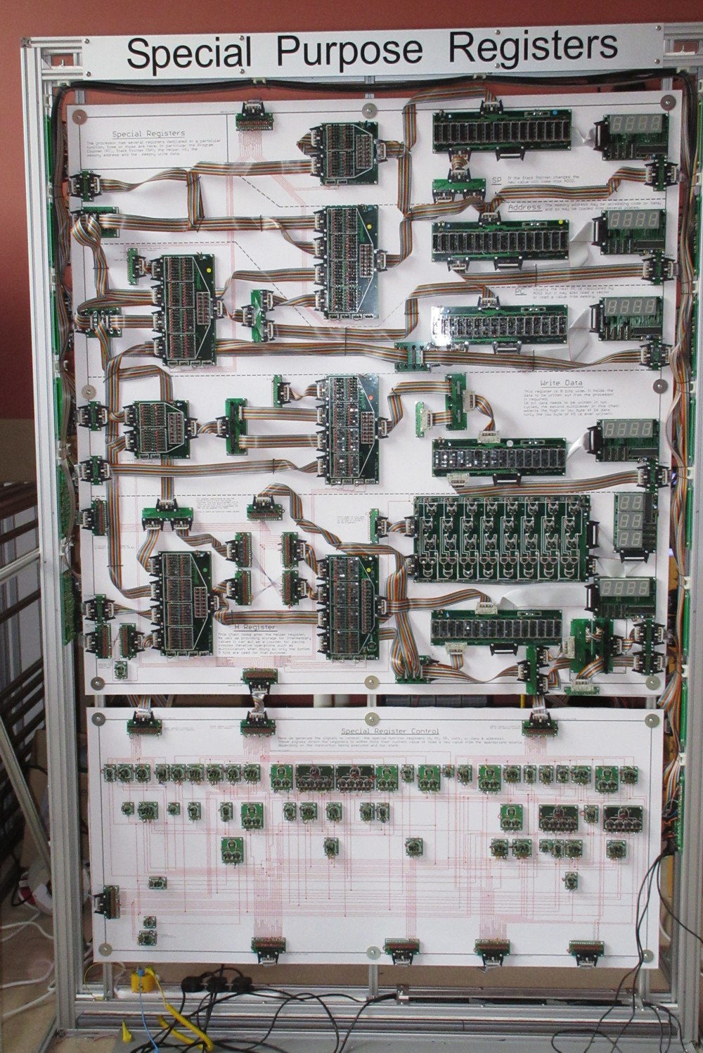
Frames were created from extruded aluminum. On all stands there is a detailed description of the functions performed by a particular computing unit. Here is a block of special-purpose registers:
In the frame there are channels for power wires. The batteries are covered with metal protection so that nothing moves if the stand is moved:
Connecting blocks are mounted on the sides of the stand.
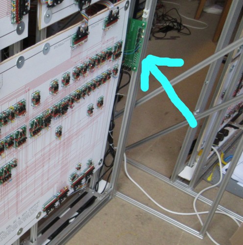
At each stand there is a service fee, which is mounted in the lower right part.
Each service card has two functions. The first is the connection and monitoring of power lines. The second is to provide access to the power clamps. In total, there are 7 stands in the system.
Modules
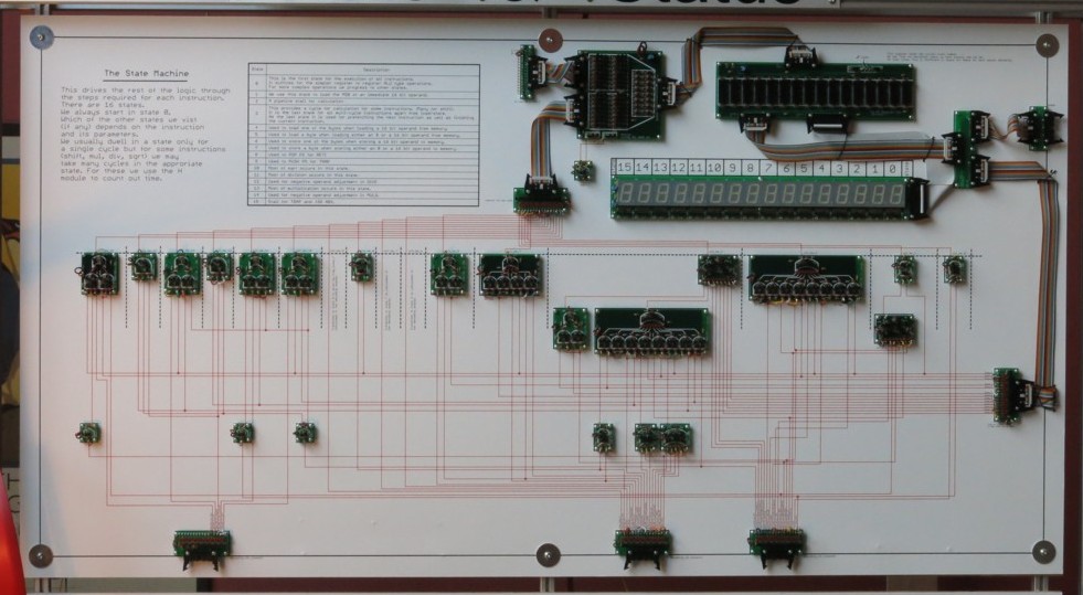
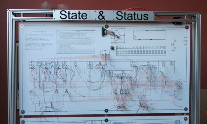
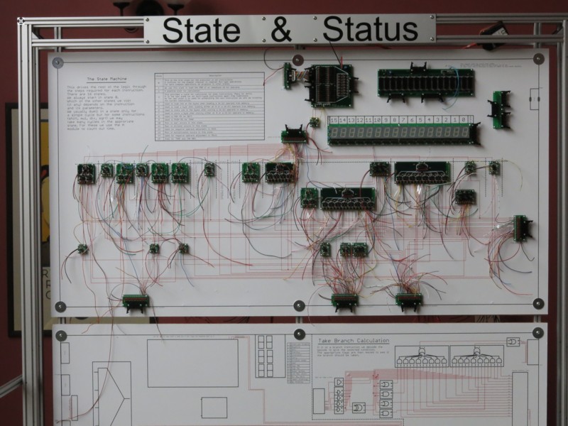
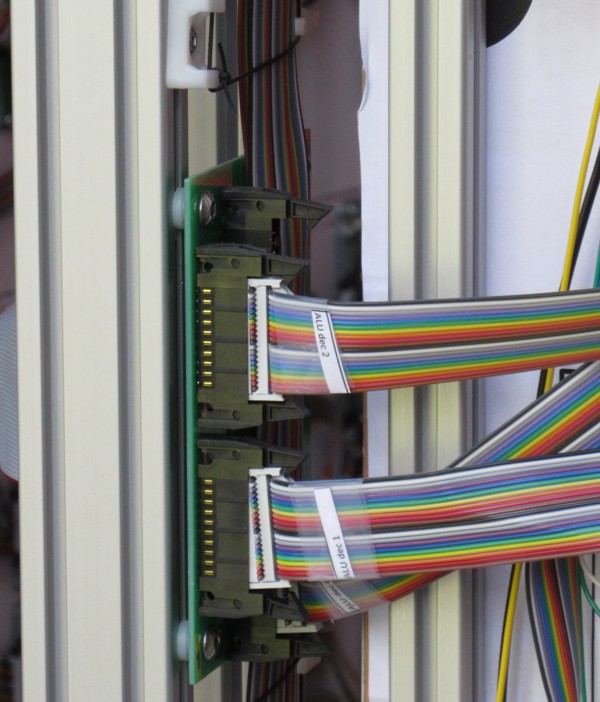
Megaprocessor is divided into a number of modules. Here is the control unit module:
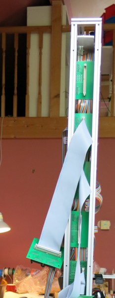
Here you can see sets of boards that implement the logic for a particular subsystem. The boards are assembled into a diagram showing what is connected with what and how. The scheme is printed on cardboard glued to plywood to ensure the rigidity of the whole structure. All connecting wires are retracted so as not to spoil the appearance of the module. Initially the wires were in front, but it didn’t look too nice.
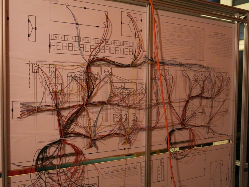
In order not to confuse anything, there is also a printout of the whole scheme behind.
The connection of all elements by wires takes a very long time.
Fees
From the very beginning, I decided that the project will use printed circuit boards. Without them, it would be impossible to create something complicated, because only connections in the system are over 100,000. Most of the project funds went to the boards. Initially, I wanted to make large boards, but it turned out to be incredibly difficult, so later I decided to divide everything into smaller boards, which was done. For design, I used CadSoft Eagle.
Other boards can be seen here .
Check
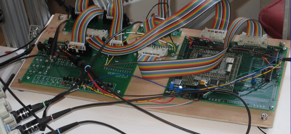
Checks were performed continuously at each stage of the project:
- Each board was tested before installation in the module;
- Each module was tested upon completion of work on it;
- Each stand was tested after completion of the installation of the modules;
- After connecting each new stand, the entire system was tested.
To verify the functioning of the boards, modules and stands, equipment from BlueChip Technologies was used.
Financial component
Total Newman spent about 40,000 pounds. At the current exchange rate (after the EU referendum, the pound exchange rate fell by 30% against the dollar) is $ 53071.
The cost of various structural elements:
| Electronics | £ 19,000 |
| Fees | £ 14,000 |
| Aluminum | £ 3,500 |
| Instruments | £ 2,000 |
| Engraving | £ 900 |
| Coloring and printing | £ 900 |
| Fasteners, plywood, etc. | £ 500 |
The cost of electronic components:
| Transistors | £ 2000 |
| Cables | £ 1800 |
| Connectors | £ 5000 |
| Chips (for debugging) | £ 850 |
| Resistors | £ 370 |
| Nutrition | £ 800 |
| LEDs | £ 1300 |
| Solder | £ 370 |
| "The rest of the iron" | £ 1100 |
general Statistics
Some stats:
| Transistors | 42,400 |
| Resistors | 50,500 |
| LEDs | 10,500 |
| Connectors | 770 |
| Contact terminals | 7,700 |
| Solder contacts | 272,300 |
| Solder weight | 4.25 kg |
| Lead weight | 2.5 kg |
| Solid wire | 1,500 m |
| 20-pin cable | 420 m |
| Total length of conductors | 9.9 km |
Fees used in the project
| Board Type | Transistors on each | LEDs on each | quantity used | Total transistors | Total LEDs |
| 2AND | five | 3 | 72 | 360 | 216 |
| 3AND | 7 | four | 18 | 126 | 72 |
| 4AND | 9 | five | five | 45 | 25 |
| 2OR | five | 3 | 54 | 270 | 162 |
| 3OR | 7 | four | 34 | 238 | 136 |
| 4OR | 9 | five | 23 | 207 | 115 |
| 5OR | eleven | 6 | sixteen | 176 | 96 |
| 8OR | 17 | 9 | 6 | 102 | 54 |
| XOR | 7 | 3 | five | 35 | 15 |
| 2x2 AND_OR | 14 | 9 | 47 | 658 | 423 |
| 2x3 AND_OR | 18 | eleven | 7 | 126 | 77 |
| 4x2 AND_OR | 26 | 17 | sixteen | 416 | 272 |
| 8x2 AND_OR | 50 | 33 | 9 | 450 | 297 |
| 1BUF | 2 | 2 | 28 | 56 | 56 |
| 4BUF | eight | eight | five | 40 | 40 |
| 4DEC | nineteen | 7 | eight | 152 | 56 |
| 16DEC | 82 | 21 | 7 | 574 | 147 |
| 2x16MUX | 118 | 52 | 3 | 354 | 156 |
| 4x16MUX | 241 | 93 | 20 | 4820 | 1860 |
| 16REG | 226 | 33 | eight | 1808 | 264 |
| 8ADD | 302 | 187 | five | 1510 | 935 |
| 8LOGIC | 158 | 126 | 3 | 474 | 378 |
| BUS SPLIT | sixteen | sixteen | 119 | 1904 | 1904 |
| BUS SPLIT (no LEDs) | 0 | 0 | 9 | 0 | 0 |
| 3x2 DIGIT (7 segments) | 0 | 0 | eight | 0 | 0 |
| 4 DIGIT (7 segments) | 0 | 0 | eleven | 0 | 0 |
| 16 DIGIT (7 segments) | 0 | 0 | 2 | 0 | 0 |
| BUS 2 BUS | 0 | 0 | 40 | 0 | 0 |
| 2 TEE | 0 | 0 | 17 | 0 | 0 |
| 4 TEE | 0 | 0 | 15 | 0 | 0 |
| BYTE_2_WORD | 0 | 0 | 13 | 0 | 0 |
| SHIFT | 37 | 34 | eight | 296 | 272 |
| 8B RAM | 766 | 64 | 32 | 24512 | 2048 |
| 4 MEM MUX | 252 | 40 | ten | 2520 | 400 |
| 2 MEM MUX | 141 | 24 | one | 141 | 24 |
| Total: | 42370 | 10,500 |
Main problems
Incorrect transistors
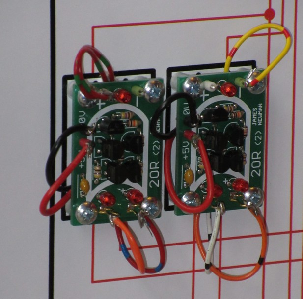
In order to facilitate his task, Newman created small boards with a maximum of symbols for the elements. On each board indicated the value of the resistor and the method of installation of the transistor.
It's simple. But in the process of work there were mistakes - about a dozen trazistorov James installed wrong. And finding them was not an easy task, given the total number of these elements in the project. Try it yourself. In the photo below - the board, where one of the transistors is installed incorrectly.
The author of the project spent hours finding a problem. Often he inspected the same incorrectly installed transistor several times without noticing it.
Connectors
Connecting with connectors is a simple task. But if there are about 500 such compounds, there is a high probability of error. And James was wrong several times.
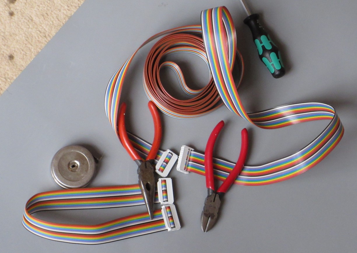
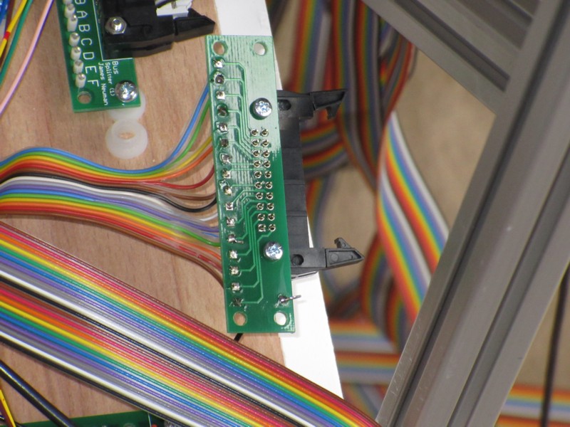
Skewed cable
In the photo, the problem can be seen right away - the cable has twisted, and several contacts have been unused. But to detect such an error in the mass of wires and connections is very difficult. Newman thought the problem was in one of the modules, and he spent an enormous amount of time checking the modules. And I had to check the cable.
Curved teeth
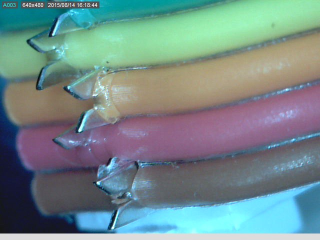
There is such a type of connection as IDC (Insulation Displacement Connector). A cable is inserted between the sharp teeth, the insulation is cut when inserted, and the cable is connected to the teeth. It's simple. In one of the cases, the “tooth” of the contact bent and touched the neighboring one, closing the circuit. Find the problem was very difficult.
And another problem of a similar nature. Only in this case, the bent "tooth" did not ensure proper contact with the wire.
Cables
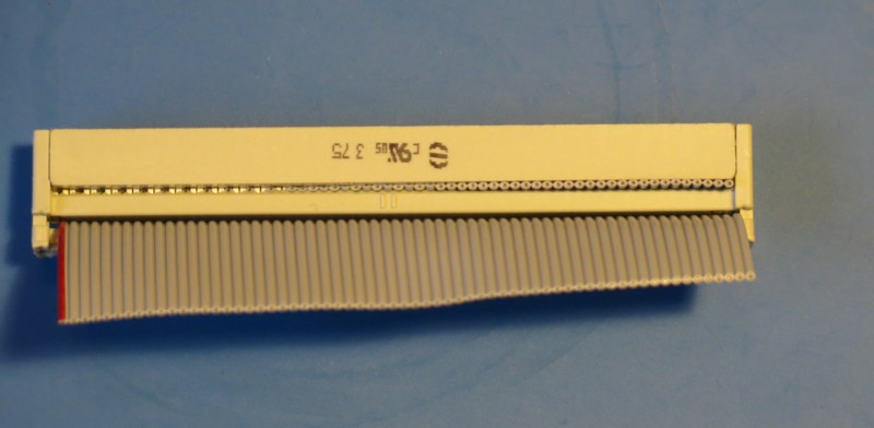
Incorrect installation of connecting cables is another problem. Moreover, it was found most often after the connection of separate modules or stands with such cables. James was sometimes mistaken in positioning the connector on the cables. Naturally, the scheme did not work. And again, the clock went searching, dialing circuits, checking elements. The photo shows a properly crimped cable with a connector and a problem cable (above).
And here is another common cause of a non-working circuit - an underexposed cable that does not provide adequate contact.
Contact closure
Short to body
There are two boards, one of which did not work as it should. As it turned out, the reason was that James screwed the board with a screwdriver and closed it on fasteners, and that one on the entire stand. To notice this with the naked eye is almost impossible.
Solder
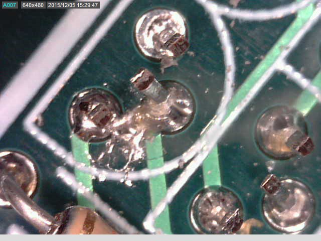
Sometimes when soldering there were characteristic problems - closing the contacts with a bridge from solder. The picture is enlarged several times the image. It is very difficult to notice this immediately - you need to examine in detail all the elements on the board.
James is a circuit engineer by profession, and he has been involved in soldering from an early age. In the photo above, the reason is the accidental drop of tin drops on the circuit. It was an isolated case for all the time, but it was a lot of messing around with him - finding the wrong ration was not easy. James initially began to check all the connections of the board and only then decided to inspect the place of soldering.
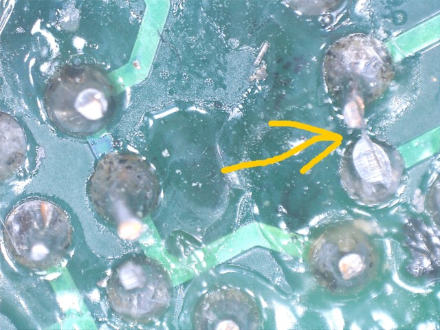
Another similar problem, it was found only with a magnifying glass - the bridge formed during soldering has the thickness of a human hair.
And still soldering
And here, for some reason, James simply forgot to solder the contacts. A number of transistor legs turned out to be “bare”, not connected to anything. This problem was quickly discovered and resolved.
Defect transistor
This was one of the most serious problems. There are many thousands of trasistors in the circuit. And the failure of just one transistor means a non-working Megaprocessor. To avoid problems, James checked each transistor before soldering. Then - after soldering. Then - all transistors on the circuit. Still, it turned out that some boards do not work, and the fault is a defective transistor. The cause of the damage is usually electrostatic discharge. Type 2N7000 transistors are very sensitive to this type of effect.
And if the board worked yesterday, then today it could no longer work. Why? The reason turned out to be unusual. This is ... a vacuum cleaner named Henry.
James Newman thought that transistors were damaged when powering up some circuits. After checking it turned out that it is not. And only after many hours of fruitless attempts to find a source of statics, he remembered that he had received a small electric shock when touching the vacuum cleaner. And with this vacuum cleaner, he cleaned some of the stands after they were ready, completely forgetting about what a vacuum cleaner could be a problem (in particular, cleaning computers or laptops with a vacuum cleaner with a vacuum cleaner, many PC manufacturers warn about this). As a result, Henry went to clean the carpets, the stands were already cleaned manually. And the transistors stopped breaking down.
Other problems
They were a huge amount. Newman worked on the project for five years, and of course, almost every day something happened. Errors, technical faults, short circuits, incorrect modeling and much more are just a few problems. It is not possible to describe all this within the framework of one article. It is better to read what James himself writes about the problems during the project.
Interview with James Newman
I could not just write about this great project without asking a few questions to the author. James immediately agreed to tell a little about his project for Geektimes readers.
How did you get the idea to create this project?
It happened five years ago. The idea arose under the influence of two factors. I experimented with transistors in order to understand in detail how they work. In addition, in my work, colleagues began to discuss the possibility of building a computer system from discrete logic circuits. And I wanted to create a computer not from individual chips, but from discrete transistors. I wanted to create a system within which a person could fit, watching how all this works. What could it be like?
How much time passed between the appearance of the idea and the beginning of the project?
Not too much. I began to carry out preparatory work for the implementation of the entire project of creating a computer system almost immediately. About a year was spent on this work and experiments.
And how big is the discrepancy between the initial plan and the actual term of the project?
It seemed to me that I could carry out my idea for the year. But the project took almost five years. This happened because, having already begun to act, I decided to build something more ambitious than I had planned.
What can you say about big or small problems that occurred during work? Which ones were critical?
The main problem that stopped working for a while is the development of a multiplexer. For some time I worked on solving the problem of the parasitic diode effect, which is relevant for MOSFETs (the vast majority of devices in MOS technology are made so that the source of the transistor is connected to the semiconductor “substrate” of the structure. This forms the so-called parasitic diode between the source and drain. Getting rid of this diode is associated with significant technological difficulties, so we learned to put up with it and even use it in circuit design solutions. - Ed. ). As a result, I developed boards that removed the problem, but they were larger than I expected.
Another problem - the difficulty of creating racks, their design was too complicated. My spatial imagination is not very good.
Well, besides this, we constantly had to solve minor issues, there were just a huge number of them both during the design process and during the implementation of the outlined plan.
If you knew about all these problems, would you start working on the project?
I suspected that something like this will be. It would not stop me. Initially, I just wanted to know how everything works. But if I knew how big the processor will turn out, and how much money will be spent on the project, I would not do it. The megaprocessor is too big for my house, and I want to find another house for it.
Have you ever thought to stop working already during the project?
There were several instances when my enthusiasm dried up, which meant slowing down. At the same time, I did not allow myself to relax completely. Every day in such cases I forced myself to do something, no matter how insignificant this task was. I told myself: "You can eat an elephant, you just need to bite off a piece after a piece."
Your project has become very famous. Are there any commercial offers? Maybe you have already decided to give the Megaprocessor to some museum or university?
No commercial offers! I do not think I could recover the money spent, and that was never the goal. I would like to give Megaprocessor to a museum or other similar organization. Negotiations are already underway.
Does the system need any special care?
No, nothing is required. Need only caution. This is especially true of static electricity - a small charge can damage something.
How do you enter data into the system?
Now I am using a modified version of the Venom Arcade Stick. First, I planned to use a serial interface that would allow the use of a PC. I developed the interface, manufactured it, but have not tested it yet.
What is the power consumption of the system?
I think about 300 watts. Most of the leaves on the LEDs.
Did anything break in the system after the Megaprocessor was ready?
The only problem I encountered was the slower operation of the system than originally planned. As it turned out, the reason for the wrong nominal pull-up resistors. It was necessary to choose resistors with a nominal value of not 10k, but only 470. Another thing is not a problem, but rather, my desire. I would like to provide the ability to adjust the display brightness. But now it's too late to think about it.
The system Megaprocessor many tens of thousands of parts. What is the likelihood that everything will work without breakdowns for a long time?
Very good question. And frightening. I think that if you do not move and touch the electronic components of the whole system, everything will be fine. But the problem is that the Megaprocessor is located in my living room, and I have to move the stands. Every time I do this, there is a possibility of damage to the connection. The probability is small. Maybe 10%. Last Saturday I discovered a malfunction on one of the boards. There were problems when moving stands before. Therefore, I considered that once out of ten during the movement of the stands a malfunction occurs. If I immerse everything in the car and install the system in a new house, I’m sure I’ll get a few faults. About ten.
Do you have any ideas for new projects?
The first thing I have to do is put the house and garden in order. They were abandoned for several years. After that, I'll see what else to do.
What can you advise to people who are planning to do something like this?
Practical advice: working on a project of this magnitude, you should have a clear idea of what you are doing. You must be a professional in your field and have a professional attitude towards each stage. When developing something, you must be sure that all created elements will be compatible with each other at the assembly stage.
Abstract advice: getting started is easy, hard to finish. Why do you want to do this? As soon as you begin to do something, you will later understand that it can be done better, and you will begin to perform this stage again. And again and again. Two years ago, I realized that if I would redo everything all the time, I would not finish anything. And I decided to dwell on the stage with a rating of “not bad”, since this stage in most cases corresponds to the plans. I know that there are a lot of mistakes in the project and a lot of things that could have been done better. But I still finished my project, and I am happy.
Source: https://habr.com/ru/post/395919/
All Articles