Cheap STM32 board + Arduino IDE UPD 08/17/2017

Want to upgrade your Arduino projects? Making them work faster, making measurements and adjustments more precisely, and adding bugs (with new devices they are inevitable). Then this article is for you.
Arduino theme is increasingly captivating the minds of humanity, but sooner or later we encounter the fact that we lack something, such as budget / size /
')
Good people understand this, and little by little they begin to introduce the STM32 to the Arduino topic , because eight-bit AVR microcontrollers, on which many Arduino boards are based, cannot always cope with the tasks.
A summary of this article in video format:
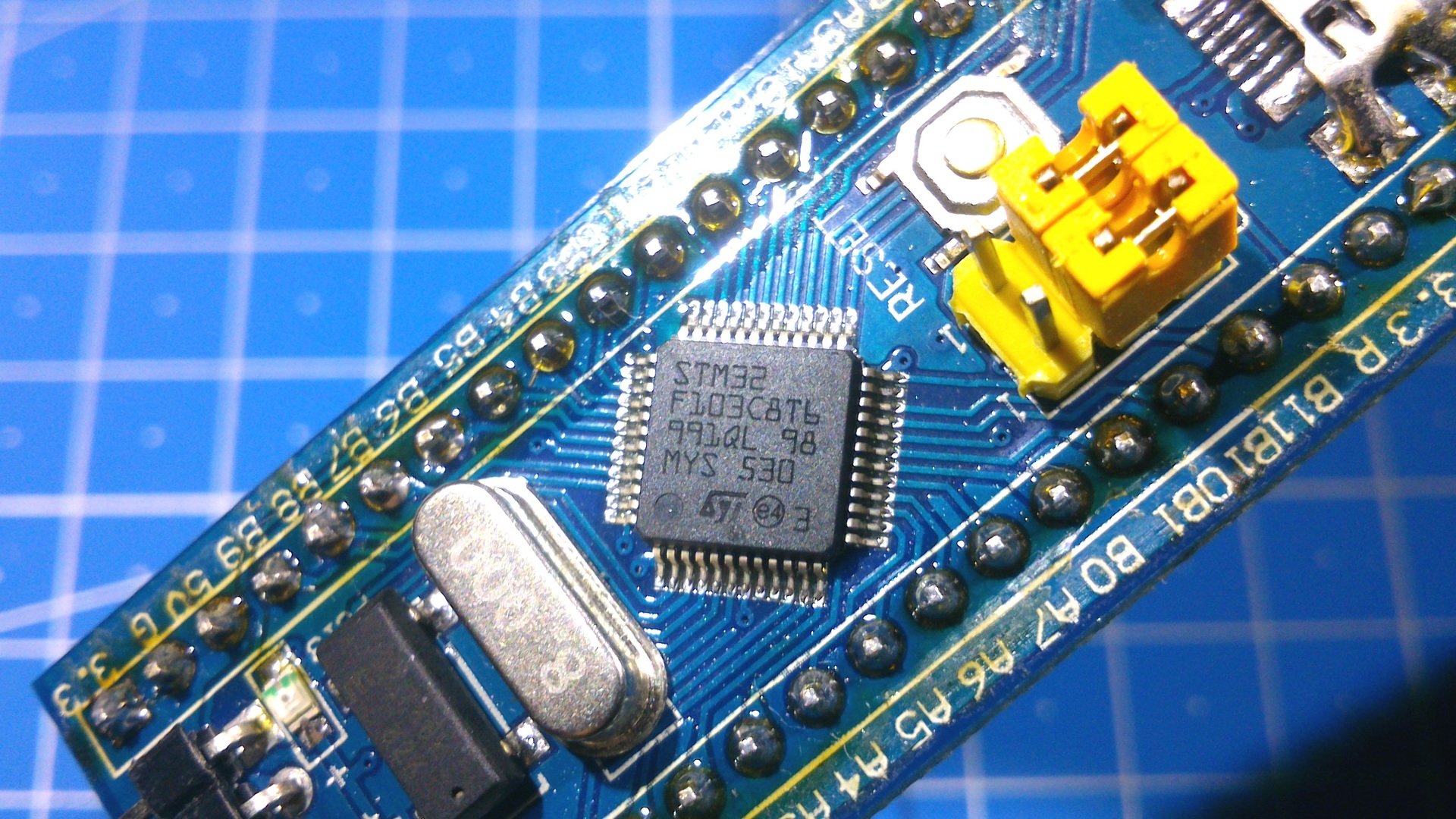
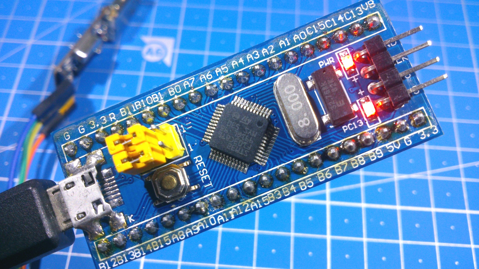
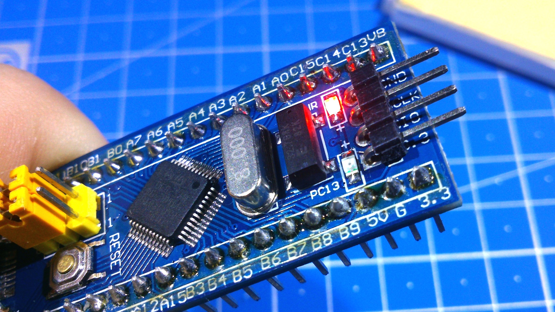
Okay, less lyrics and closer to the topic. In this article, I will look at a cheap debugging board, which is based on the STM32F103C8T6 microcontroller base:
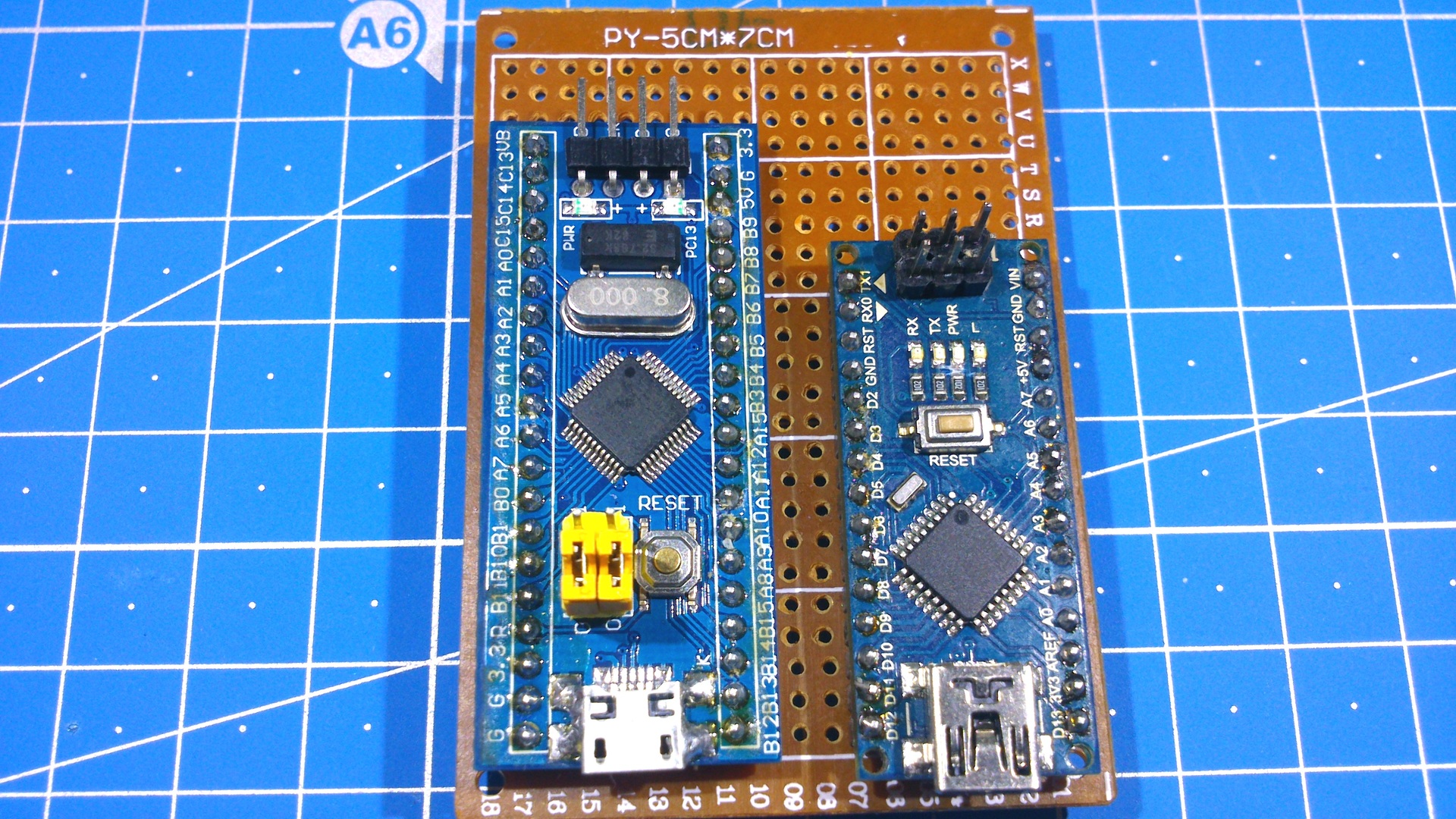
For a start, let's compare the main parameters of the STM32 board, and its counterpart for the price - Arduino Nano V3.0:
- The working frequency is 72 MHz, against 16 for the Arduino;
- The amount of flash memory is 64 KB, against 32;
- RAM, it is also RAM (where variables are stored), STM32 has as much as 20 Kbytes, and Arduinka has only 2;
- A fast 12-bit ADC, while the Arduino boards, which are based on AVR microcontrollers (this is usually the majority), use a 10-bit one. This means that in the case of STM32, the analogRead (*) function; will return 0..4095 versus 0..1023, which in the first case leads to more accurate measurements;
- 16-bit hardware PWM, versus 8 in Arduino boards, that is, the
analogWrite (*)function;pwmWrite (*); can take the value 0..65535, against the poor 0..255. This will allow even more precise control of our engines, servami and other devices that are driven by PWM; - Hardware work with USB, more than one Arduino board worth less than $ 2 cannot boast;
- The supply voltage is from 2 to 3.6V (just sharpened for 2 AA batteries), against 2.7 ... 5V for the Arduino boards;
- Prices at the time of this writing - 1.9 dollars against 1.8 (aliexpress).
Obviously, the STM32-based debugging board wins in all parameters from the Arduino Nano, except the cost is the exception, but agree that 10 cents is a good price for high performance, and about the periphery that is stuffed with STM32, I’m generally silent, which only DMA costs or a real-time clock integrated into the microcontroller.
All this in total makes this board extremely attractive in everything except one - for a beginner, like me, the STM32 theme seems too time consuming, there are entire websites dedicated to programming these microcontrollers. But if you make friends with the STM32 Arduino IDE, the threshold of entry drops to an extremely low level. Although, as they say, "In each barrel of honey, there is a fly in the ointment," but more on that below.
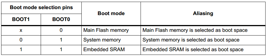
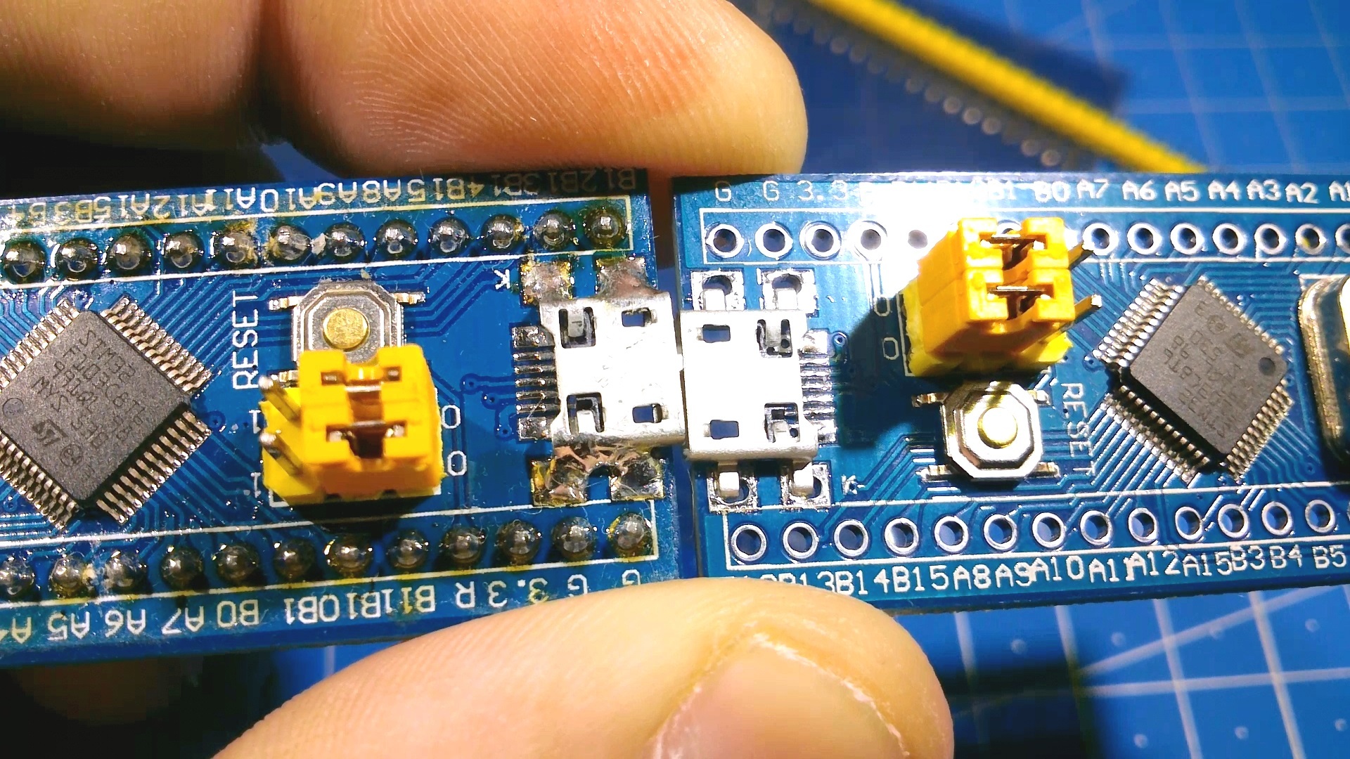
Let's start preparing the board for working with the Arduino IDE. The first thing that needs to be done is to upload a special bootloader into the microcontroller, which will allow to flash the board through hardware USB, and directly from the development environment. To do this, move the upper jumper (aka “BOOT0”) to the “1” position:

What are BOOT0 and BOOT1 jumpers for?
The fact is that in STM32 from the factory, a special bootloader is stitched into the so-called system memory (system memory), which allows you to flash the board through the most common USB to UART adapter, without resorting to specific programmers like ST-Link V2 .
Next we need an adapter from USB to UART. It is worth remembering that the STM32, this 3.3 V logic , compatibility with 5 volt is not guaranteed, therefore it is recommended to use USB to UART, which has the ability to select modes of operation with 3.3 / 5V logic. I used a cheap CH340G based adapter:
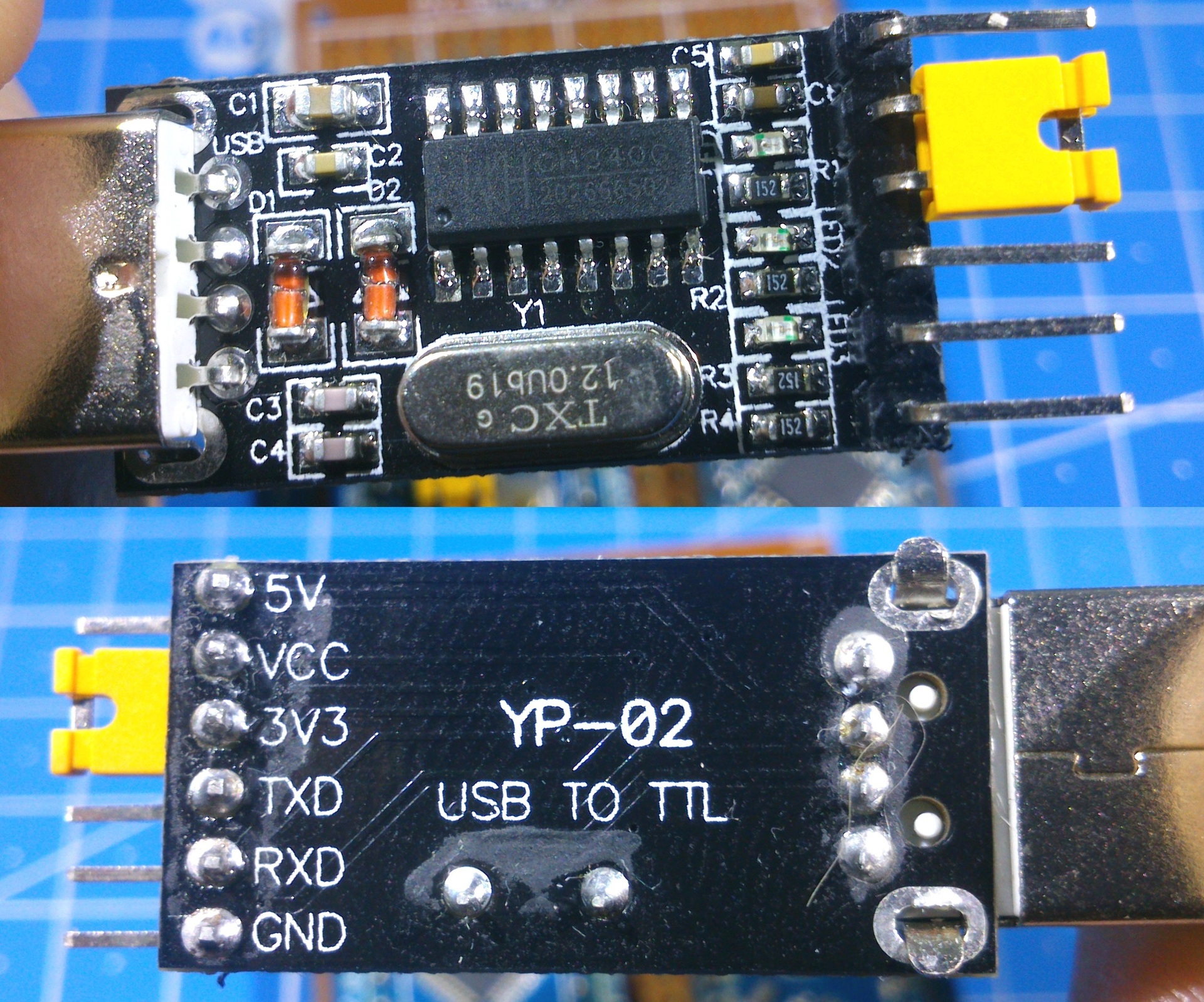
* As you can see, the manufacturer did not wrap up with the flux remover, of course, it doesn’t affect the work.
I connected the adapter to the USB to UART adapter as follows:
G <-> GND;
5V <-> 5V;
PA10 <-> TXD;
PA9 <-> RXD.
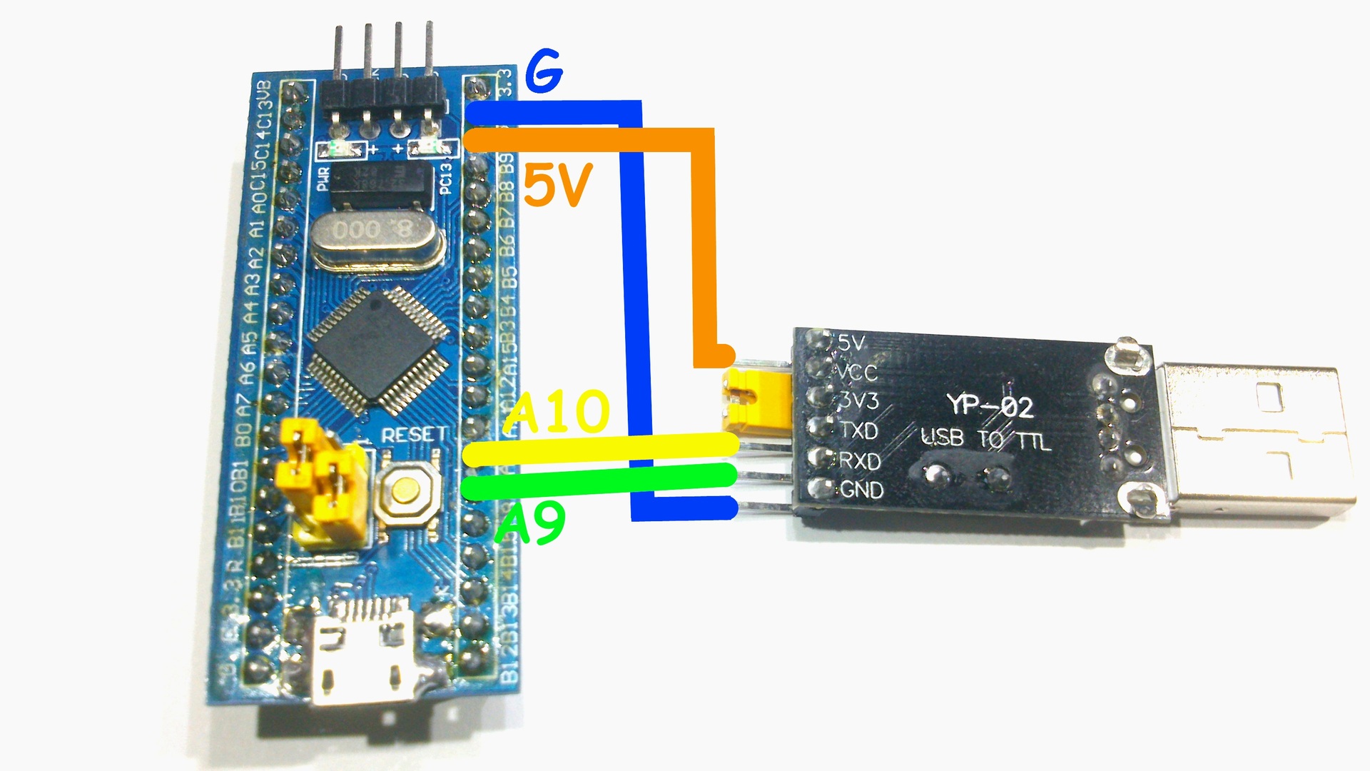
* PA10 / PA9 on the board are simply signed as A10 / A9 - these ports are the first hardware USART, all of them are on board 3, just here there are 2 hardware I2C and 2 SPI.
For the sake of convenience, it powered the board from 5 V, for power supply from 3.3 V, there is a pin “3.3” on the board. Attention, 5 V can easily disable the microcontroller , so pay due attention to the connection.
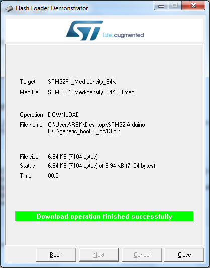
Download, install and run Flash Loader Demonstrator (available in the archive for the article):
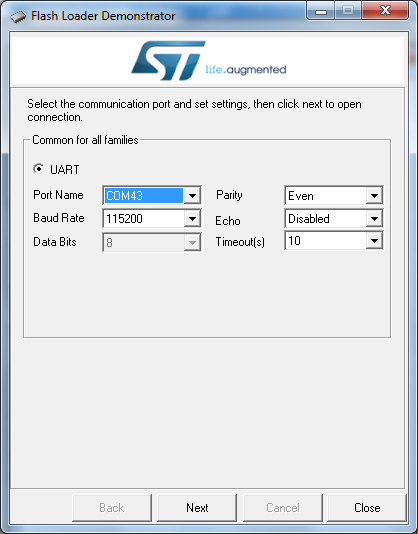
Select the COM port number of our adapter, in my case it is COM43, then click “Next”:
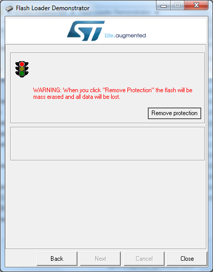
Since I have a new microcontroller, nobody has ever written a
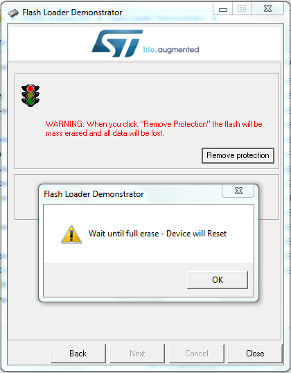
Click "OK":
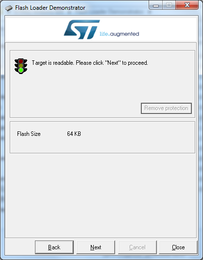
Since my debug board is based on the STM32F103 C8 microcontroller - 64 KB of flash memory is here, there is also the STM32F103 CB microcontroller, where Flash is twice as large.
Next click "Next":
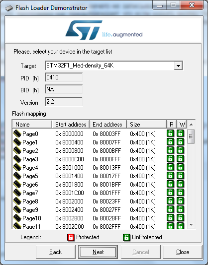
Again “Next”, and see the following window:
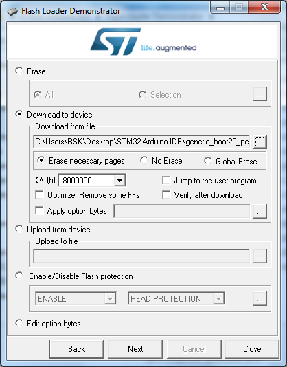
Select "Download to device" and click on the "...":
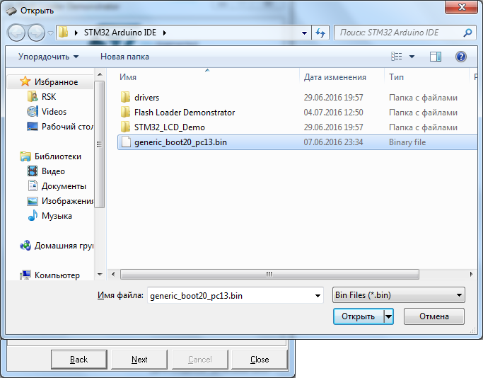
We change the file type to * .bin and open the file “generic_boot20_pc13.bin” (also present in the archive) which can be taken from the STM32duino-bootloader project.
Next, click on the button “Next”, after the bootloader firmware, we will see the green light:
Then you need to download, for the Arduino IDE development environment, a special STM32 kernel (also available in the archive for the article).
Proven kernel performance on the Arduino IDE version 1.6.9 .
Next, unzip the contents to My Documents \ Arduino \ hardware:
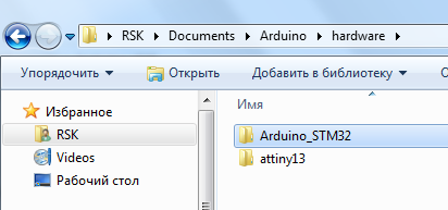
In my case, the full path looks like this - "C: \ Users \ RSK \ Documents \ Arduino \ hardware"
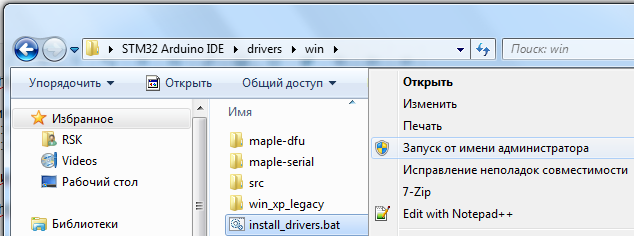
Of course, the system will not be able to determine the device, so you must also install drivers on the board. Go to the folder "My Documents \ Arduino \ hardware \ Arduino_STM32 \ drivers \ win" (or "drivers \ win", in the case of an archive for the article), and run the file "install_drivers.bat" as administrator:
After this, the upper jumper (the one that is “BOOT0”) is transferred to the “0” position and we connect the board to the computer via the microUSB cable:
It should be defined in the device manager as either "Maple DFU" or "Maple Serial (COM *)":
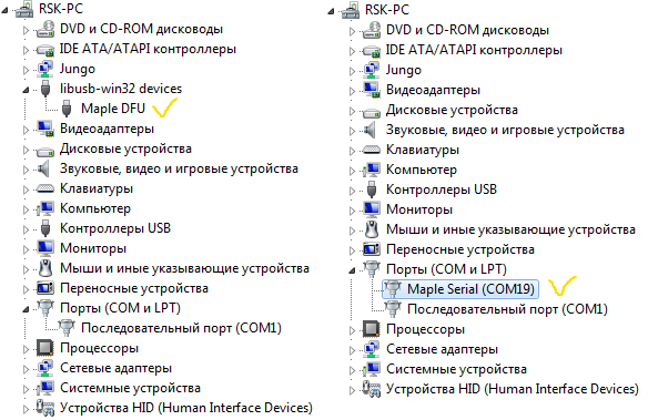
It is not entirely clear why after the first connection the board is determined differently, on different computers, but not the essence, proceed to setting up the Arduino IDE.
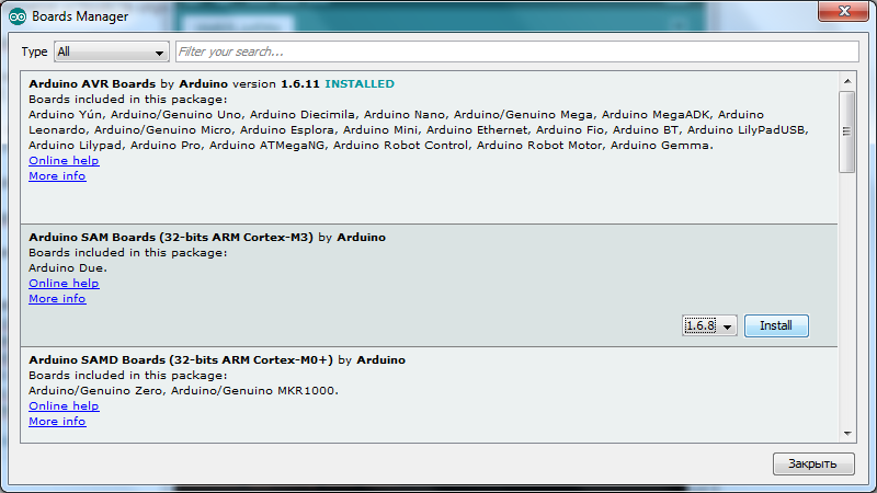
Launch the development environment, then Tools -> Board -> Boards Manager:
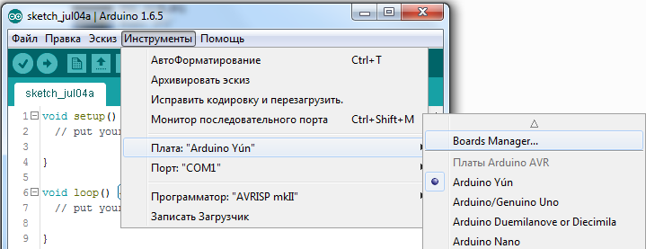
Here you need to install the core for the Arduino Due. Select the latest version and click "Install":
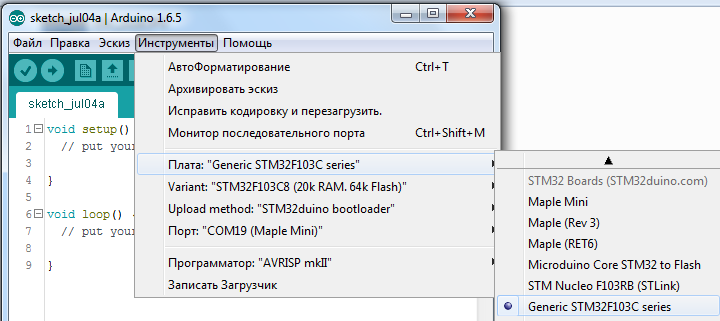
Then Tools -> Board -> "Generic STM32F103C", then Variant: "STM32F103C8 (20k RAM. 64k Flash)", Upload Method: "STM32duino bootloader", Port - the number of the COM port of the board, in general, everything is as on the screen:
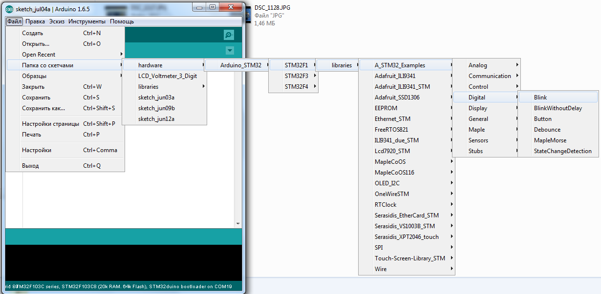
That's it, the board is ready for firmware and programming in the Arduino IDE development environment. Let's skip some sketch from the examples that are “stitched” into the kernel, go to File -> Folder with Sketches -> hardware -> Arduino_STM32 -> STM32F1 -> libraries -> A_STM32_Examples -> Digital -> Blink:
Classic "Hello World" in the world of microcontrollers. Change PB1 to PC13, since the LED on the board is connected to this port:
* By the way, it lights up at a low level on the leg of PC13.
Press the "Load" button, after the firmware, the development environment will produce something like:

“Done!
Resetting USB to switch back to runtime mode
error resetting after download: usb_reset: couldn’t reset device, win error: The specified file could not be found. ”.
But the firmware is loaded successfully, although not always the case, sometimes the Arduino IDE issues other messages.
Couldn't find the DFU device
When you see a message like:
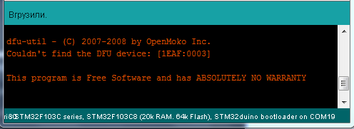
“Dfu-util - © 2007-2008 by OpenMoko Inc.
Couldn't find the DFU device: [1EAF: 0003]
This program is ABSOLUTELY NO WARRANTY Software
This means that the board failed to flash.
“Dfu-util - © 2007-2008 by OpenMoko Inc.
Couldn't find the DFU device: [1EAF: 0003]
This program is ABSOLUTELY NO WARRANTY Software
This means that the board failed to flash.
Searching for DFU device [1EAF: 0003] ...
When the development environment issues:
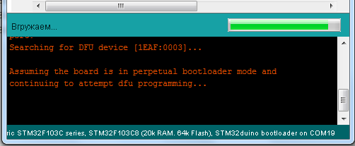
“Searching for DFU device [1EAF: 0003] ...
Assuming the board is in perpetual bootloader mode and continuing to attempt dfu programming ... "
And nothing else happens, try to restart the board by clicking the reset button at this moment. By analogy, this is like with the Arduino Pro Mini.
“Searching for DFU device [1EAF: 0003] ...
Assuming the board is in perpetual bootloader mode and continuing to attempt dfu programming ... "
And nothing else happens, try to restart the board by clicking the reset button at this moment. By analogy, this is like with the Arduino Pro Mini.
And now about the “spoon of tar”, which I wrote about at the beginning of the article, for some reason it is not always possible to flash the board in the development environment, even more, it is not always determined by the computer. I decided this for myself as follows, before downloading the firmware (before pressing the “Load” button), click “Reset” on the board, and after the firmware, I reload the board again. In this case, the percentage of the probability that the board will be flashed is 99%. It is not clear why it works this way, but true. I think that sooner or later this joint will be corrected, and everything will automatically restart as needed. And in order to fix this faster, it is necessary that the community of this great STM32 debug card grows, so share this article with friends, especially with programmer friends.
About pinouts:
Clickable
The best I managed to find was the pinout of the microcontroller itself (open in a new tab):
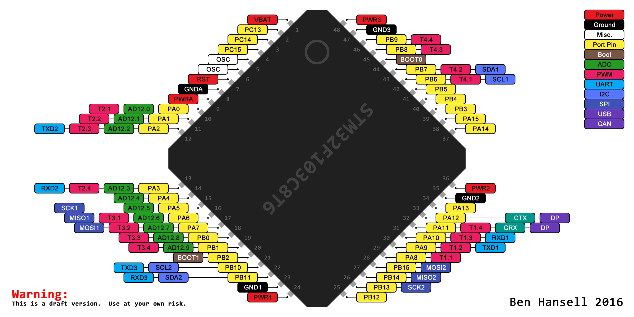
(c) www.stm32duino.com/viewtopic.php?p=11137
The port must be addressed using the full name, for example:
digitalWrite (PB0, LOW);
analogWrite (PA8, 65535); pwmWrite (PA8,65535);
analogRead (PA0);
LiquidCrystal lcd (PB0, PA7, PA6, PA5, PA4, PA3);
I also recommend going to the docs.leaflabs.com/docs.leaflabs.com/index.html website there is a lot of interesting things about programming in the Arduino IDE, though in English.
I rummaged through the kernel files, and found one interesting file:
Documents \ Arduino \ hardware \ Arduino_STM32 \ STM32F1 \ variants \ generic_stm32f103c \ board.cpp
It contains all the ports that support:
So keep that in mind. Although this is more than enough from the board, worth 1.9 dollars.
I also noticed that the pins of the PA12 / PA11 are connected to the D + / D- USB, once again it’s better not to touch them at all, for just that, it's not a 2-dollar piece of fiberglass plastic with a chip, but a computer motherboard.
(c) www.stm32duino.com/viewtopic.php?p=11137
The port must be addressed using the full name, for example:
digitalWrite (PB0, LOW);
analogRead (PA0);
LiquidCrystal lcd (PB0, PA7, PA6, PA5, PA4, PA3);
I also recommend going to the docs.leaflabs.com/docs.leaflabs.com/index.html website there is a lot of interesting things about programming in the Arduino IDE, though in English.
I rummaged through the kernel files, and found one interesting file:
Documents \ Arduino \ hardware \ Arduino_STM32 \ STM32F1 \ variants \ generic_stm32f103c \ board.cpp
It contains all the ports that support:
- PWM, that is, the function
analogWrite ();pwmWrite (); - PB0, PA7, PA6, PA3, PA2, PA1, PA0, PB7, PB6, PA10, PA9, PA8, and this is by no means all that are marked on the pinout of the chip; - ADC, ala analogRead (); - PB0, PA7, PA6, PA5, PA4, PA3, PA2, PA1, PA0.
So keep that in mind. Although this is more than enough from the board, worth 1.9 dollars.
I also noticed that the pins of the PA12 / PA11 are connected to the D + / D- USB, once again it’s better not to touch them at all, for just that, it's not a 2-dollar piece of fiberglass plastic with a chip, but a computer motherboard.
Debug card layout:
Clickable

And lastly:

Hi geektimes.ru
//https://github.com/mk90/LiquidCrystalRus //STM32 ! #include <LiquidCrystalRus.h> LiquidCrystalRus lcd(PB9, PB8, PB7, PB6, PB5, PB4); void setup() { lcd.begin(16, 2); lcd.print(""); lcd.setCursor(0, 1); lcd.print("geektimes.ru"); } void loop() { lcd.setCursor(14, 1); lcd.print(millis() / 1000); } References:
Archive to the article ;
Comrade Roger Clark's website for STM32 porting , questions / suggestions / thanks, everything is there;
https://github.com/rogerclarkmelbourne/Arduino_STM32 ;
http://docs.leaflabs.com/docs.leaflabs.com/index.html - this is the project that Roger took as a basis, so there is a lot of useful things, though in English;
Arduino IDE version 1.6.5-r5 can be downloaded here ;
My article, to some extent intersects with the " STM32 vs Arduino " comrade @RaJa ;
Datasheet on STM32F103C8T6 ;
All my publications are on geektimes .
UPD 07.15.2016
Proven kernel performance on the Arduino IDE version 1.6.9:
geektimes.ru/post/277928/#comment_9532576
PS
What else did you forget
I forgot to add a photo of the board on the reverse side:
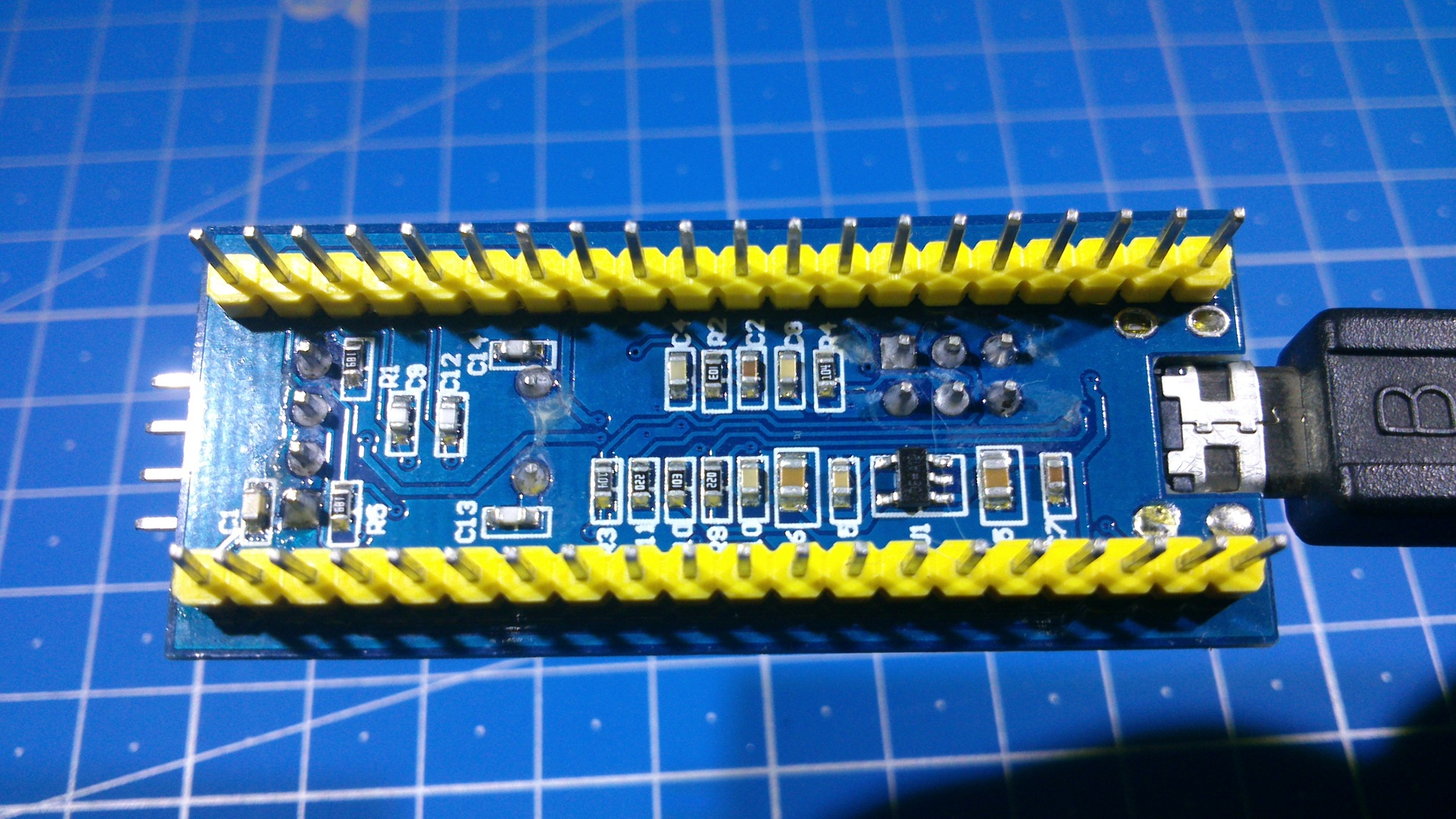
There is almost nothing, a stabilizer and some resistors with capacitors.
I also did not say that the microUSB connector was additionally soldered:
Because not really inspired confidence ration, or rather, its complete absence.
There is almost nothing, a stabilizer and some resistors with capacitors.
I also did not say that the microUSB connector was additionally soldered:
Because not really inspired confidence ration, or rather, its complete absence.
Source: https://habr.com/ru/post/395577/
All Articles