Brew beer with MP8036multi module
One of the clients asked us to select the appropriate module for solving their problem.
The module is planned to be used as part of a small private brewery. The task of the module was the strict maintenance of a certain temperature-time regime of the wort in one of the cycles. As the heater is applied TEN power of 3 kW.
')
The task is as follows:
- heating and maintaining the wort to 60 ° C for 30 minutes;
- heating and holding at 70 ° C for 20 minutes;
- heating and holding up to 80 ° C for 10 minutes;
- indication of the end of the cycle and turning off the heater;
- indication of the passage of the cycle;
- alarm of temperature sensor failure or exceeding the maximum allowable temperature.
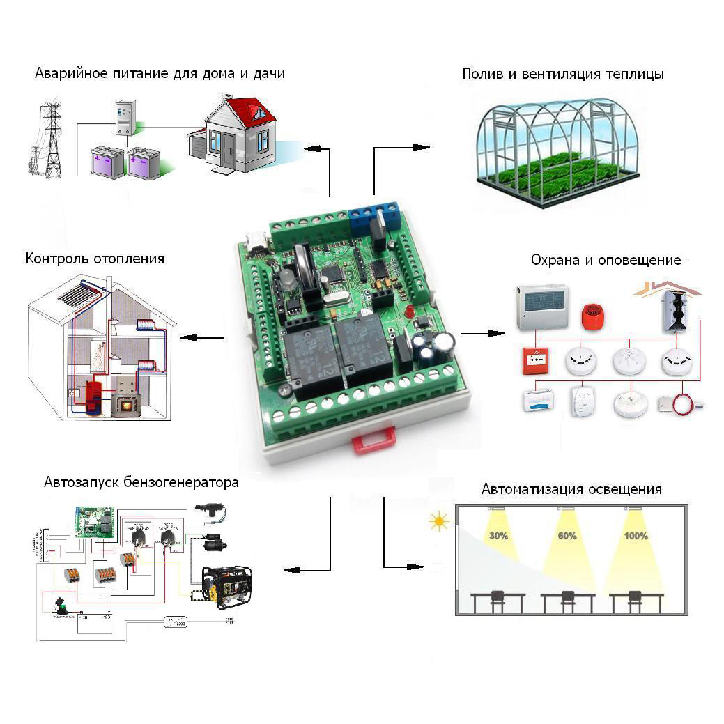
As a control module, it was decided to use the universal programmable MP8036multi .
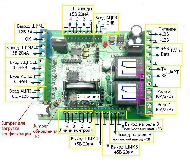
Fig. one
The uniqueness of the MP8036multi module lies in the flexibility of its configuration: the state of the controller outputs may depend on various combinations of input states. However, programming this module for any particular task does not cause any difficulties. Based on the MP8036multi, you can automate the lighting system, control the heating, emergency power supply at home or summer house, automate watering and ventilation of the greenhouse, as well as implement many other solutions.
In general approximation, the heating system has the following main controls and alarms:
- START / STOP button - INPUT4;
- accident indicator - PWM1;
- cycle control indication - OUT1, OUTPUT2, OUTPUT3;
- temperature sensor - DT1;
- indication of the end of the cycle - RELAY2;
- control channel of heating elements - RELAY1.
Any power source with a voltage of 12V and a current of at least 100 mA will be suitable for powering the module. As such a unit, we recommend using the well-proven AC / DC converter PW1245 . There are two relays installed on the module with a maximum permissible current of 10A 250V, which is not enough to control the customer’s heating elements (3 kW power). Therefore, we recommend using the MP146 power module as a control relay for the heating elements . The contacts of this module are designed to turn on electrical appliances with a voltage of up to 250V and a power of up to 6.6 kW.
Management is as follows:
When you turn on the switch at INPUT4, the program starts. Since for identical events, different operating modes are required, additional OUTPUT 1, OUTPUT 2 and OUTPUT 3 are involved. These outputs create additional events for which the desired mode of operation is selected. In turn, each timer is limited by its temperature range. TENOM is controlled by RELAY1 through the power module MP146.
After the expiration of 60 minutes there is a complete disconnection of the heater, and an indication on RELE2 signals the end of the cycle.
If during operation the temperature goes beyond the maximum limit of the process or the thermal sensor fails, an alarm will be triggered at the PWM1 output.
The process of the heating cycle operation can be observed at the OUTPUT 1 OUT 2 and OUT 3 outputs. Forced shutdown and restart of the cycle is carried out using a switch installed on INPUT4.
The text of the program and the electric control circuit of the heater can be seen below.
Program
// input4 - on / off
// exit1 - 30 min
// exit2 - 50 min
// exit3 - 60 min
// DT1 - 60, 70, 80
// RELAY1 - TEN
RELAY CONFIGURATION RESET
RELAY 1. MODE_PO_MULSE = 1
RELAY 1. MODE. STATUS = DISABLED
RELAY1. MODE1. CONDITION1: INPUT4 = 1
RELAY 1. MODE1. CONDIT2: OUTPUT1 = 0
RELAY 1. MODE1. CONDITION3: OUTPUT2 = 0
RELAY1. MODE1. CONDITION4: OUTPUT3 = 0
RELAY 1. MODE1. CONDITION 5: OUT1 = 1
RELAY 1. MODE1. CONDITION6: OUTPUT2 = 1
RELAY 1. MODE1. CONDITION7: OUTPUT3 = 1
RELAY 1. MODE1. CONDITION8: DT1> = 60
RELAY 1. MODE1. CONDITION9: DT1> = 70
RELAY1. MODE1. CONDITION10: DT1> = 80
RELAY 1. MODE1. CONDITION11: INPUT4 = 0
RELAY 1. MODE1. CONDITION12: RELAY2 = ENABLE
RELAY1.REAM1.LOGICA_USLOVY = (Y11 AND (Y4 OR (Y5 AND Y6 AND Y7 AND Y8) OR (Y2 AND Y6 AND Y7 And Y9) OR (Y2 And Y3 And Y7 And U10))) OR Y1 OR Y12
RELAY 1. MODE. STATUS = ENABLE
RELAY 1. MODE2. CONDITION1: INPUT4 = 1
RELAY 1. MODE 2. CONDIT2: OUTPUT1 = 0
RELAY 1. MODE 2. CONDIT 3: OUT 2 = 0
RELAY 1. MODE2. CONDITION4: OUTPUT3 = 0
RELAY 1. MODE 2. CONDITION 5: OUT1 = 1
RELAY 1. MODE 2. CONDITION 6: OUTPUT 2 = 1
RELAY 1. MODE2. CONDITION7: OUTPUT3 = 1
RELAY 1. MODE 2. CONDITION8: DT1 <60
RELAY 1. MODE 2. CONDITION9: DT1 <70
RELAY 1. MODE 2. CONDITION10: DT1 <80
RELAY1. MODE2. CONDITION11: INPUT4 = 0
RELAY1. MODE2. LOGIC OF THE CONDITIONS = Y11 AND ((Y5 AND Y6 AND Y7 AND Y8) OR (Y2 And Y6 And Y7 And Y9) OR (Y2 And Y3 And U7 And U10))
RELAY2. MODE_PO_MULSE = 1
RELAY 2. MODE. STATUS = DISABLED
RELAY2. MODE1. CONDITION1: INPUT4 = 1
RELAY 2. MODE1. CONDITION2: OUTPUT3 = 1
RELE2. MODE. LOGIC OF THE CONDITIONS: U1 OR U2
RELAY 2. MODE 2. STATUS = INCLUDED
RELAY 2. MODE 2. DELAY = 1 (s)
RELAY2. MODE2. CONDITION1: INPUT4 = 0
RELAY2. MODE2. CONDITION2: OUTPUT3 = 0
RELAY 2. REGIME 2. LOGIC OF THE CONDITIONS: U1 AND U2
//T.k. With the same events, different operating modes are required, additional OUTPUT 1 OUTPUT 2 and OUTPUT 3 are involved. These outputs create additional events for which the desired mode of operation is selected.
OUTPUT1. MODE_PO_MULSE = 1
OUTPUT1. MODE1. STATUS = 0
OUTPUT1. MODE1. CONDITION1: INPUT4 = 1
OUTPUT1. MODE1. LOGIC_OUTIONS = U1
OUTPUT1. MODE2. STATUS = 1
OUTPUT1. MODE2. TIME_ACTION = 30 (min)
OUTPUT1. MODE2. CONDITION1: INPUT4 = 0
OUTPUT1. MODE2. LOGIC_OUTIONS = U1
OUTPUT2.REW_NUMBERING MODE = 1
OUTPUT2. MODE1. STATUS = 0
OUTPUT2. MODE1. CONDITION1: INPUT4 = 1
OUTPUT2. MODE. LOGIC_OUTIONS = U1
OUTPUT2. MODE2. STATUS = 1
OUTPUT2. MODE2. TIME_ACTION = 50 (min)
OUTPUT2. MODE2. CONDITION1: INPUT4 = 0
OUTPUT2. MODE2. LOGIC_OUTIONS = U1
OUTPUT3. MODE_PO_MULSE = 1
OUTPUT3. MODE1. STATUS = 0
OUTPUT3. MODE1. CONDITION1: INPUT4 = 1
OUTPUT3. MODE. LOGIC_OUTIONS = U1
OUTPUT3. MODE2. STATUS = 1
OUTPUT3. MODE2. TIME_ACTION = 60 (min)
OUTPUT3. MODE2. CONDITION1: INPUT4 = 0
OUTPUT3. MODE2. LOGIC OF THE CONDITIONS = U1
PWM1. MODE_PROPERTY = 1
PWM1. MODE1. FUNCTION = DISCRETE_OUT
PWM1. MODE1. STATUS = 0
PWM1. MODE1. CONDITION1: DT1 <81
PWM1. MODE1. CONDIT2: INPUT2 = 0
PWM1. MODE1. LOGIC_OUTIONS = U1 or U2
PWM1. MODE2. FUNCTION = DISCRETE_INIT
PWM1. MODE2. STATUS = 1
PWM1. MODE2. DELAY = 1 (s)
PWM1. MODE2. CONDITION1: INPUT1 = 1
PWM1. MODE2. CONDITION2: DT1> 81
PWM1. MODE2. LOGIC_UNITIES = U1 or U2

Connection diagram Fig. 2
Channel PWM1 is in discrete output mode. But if necessary, it can always be used as intended. When practicing the program, do not forget to add the DT1 temperature sensors, according to the configuration instructions. Please note that when adding two or more sensors, you must connect them in turn. The time intervals and temperature range are adjusted locally.
If when debugging a program you often have to load the configuration into the module, but you do not want to add temperature sensors every time and reconfigure the ADC lines, use only resetting the changed lines:
RELAY1 CONFIGURATION RESET
RESET RELAY2 CONFIGURATION
RESET CONFIGURATION OUTPUT1
RESET CONFIGURATION OUTPUT2
RESET CONFIGURATION OUTPUT3
RESET OF PWM CONFIGURATION
With such commands, the settings of only one specified line will be reset, while the remaining settings will remain unchanged.
Each time the program is loaded into the module’s memory, the configurator program must be restarted. Connecting power, sensor and power relay should not cause any difficulties. The text of the program is also intuitive. We recommend using the PW1245 AC / DC converter to power the module.
We hope that the proposed solution will suit the client. We are waiting for his response, we are ready for the whole team to take part in setting up the equipment and the subsequent tasting of the finished product!
Ps Data on heating and shutter speed are given conditional, used only for writing the program. Required data is substituted by the user.
More applications:
MP8036multi: an example of a thermostat
MP8036multi: example of a timer
We manage the autonomous power of a country house
Source: https://habr.com/ru/post/395539/
All Articles