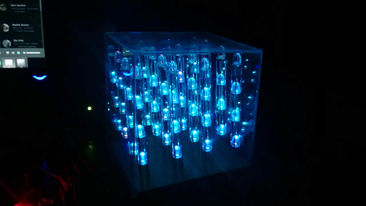
LED RGB 4x4x4 cube for music visualization
In this article we will talk about the experience of assembling a 4x4x4 cube on RGB LEDs, as well as about developing the software necessary to use the cube as a sound visualizer. Used Arconino Uno microcontroller.
In the study of such projects, a realization was discovered under the name “Charliecube” by authorship Asher Glick and Kevin Baker. This option is remarkable in that, unlike other implementations, it does not provide for counters, shift registers or any other components for building a cube for its subsequent programming and only involves 16 microcontroller pins (allowing you to address 64 LEDs). The basis of this implementation is the LED display design called "Charliplexing".
The digital outputs of the microcontrollers have a three-valued logic: connected to the power supply, connected to the “ground” and not connected to anything. If we need to light the LED, it is necessary to apply "+" to X and "-" to "Y", only in this case it will be lit. If nothing is applied to Y, the LED will not light up. More information about the method can be found in the article of the same name on Wikipedia , below is a description of the work specifically in our case.
')
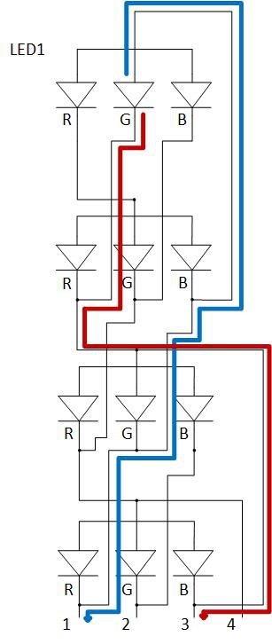
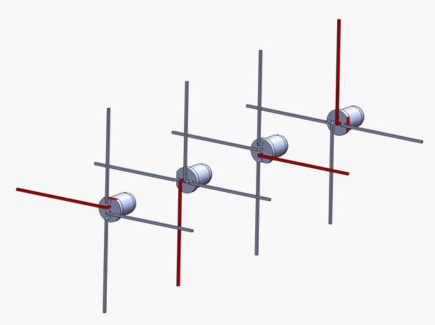
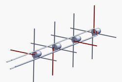
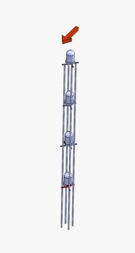
LED column diagram
Suppose we want to turn on LED1 in green. If you follow the blue line, you can see that you need to submit a “+” to input 1. Following the red line, we understand that you need to submit “-” to input 3. Nothing is given to the other inputs.
It was decided that the entire analysis of the music will be performed on a PC connected to the cube. The basic idea: the PC analyzes the sound recording channel, converts the sound into frequency information and transmits data about the rhythm of the music to the Arduino. The microcontroller further highlights certain LEDs based on this information.
Since the authors of the project have a lot of experience with Ruby, in the framework of the project I wanted to resort to this particular programming language. An article by David Guttman describing the visualization of sound on JRuby using the ruby-processing heme and the Minim java library was discovered. The found article was taken as the basis for writing a visualizer.
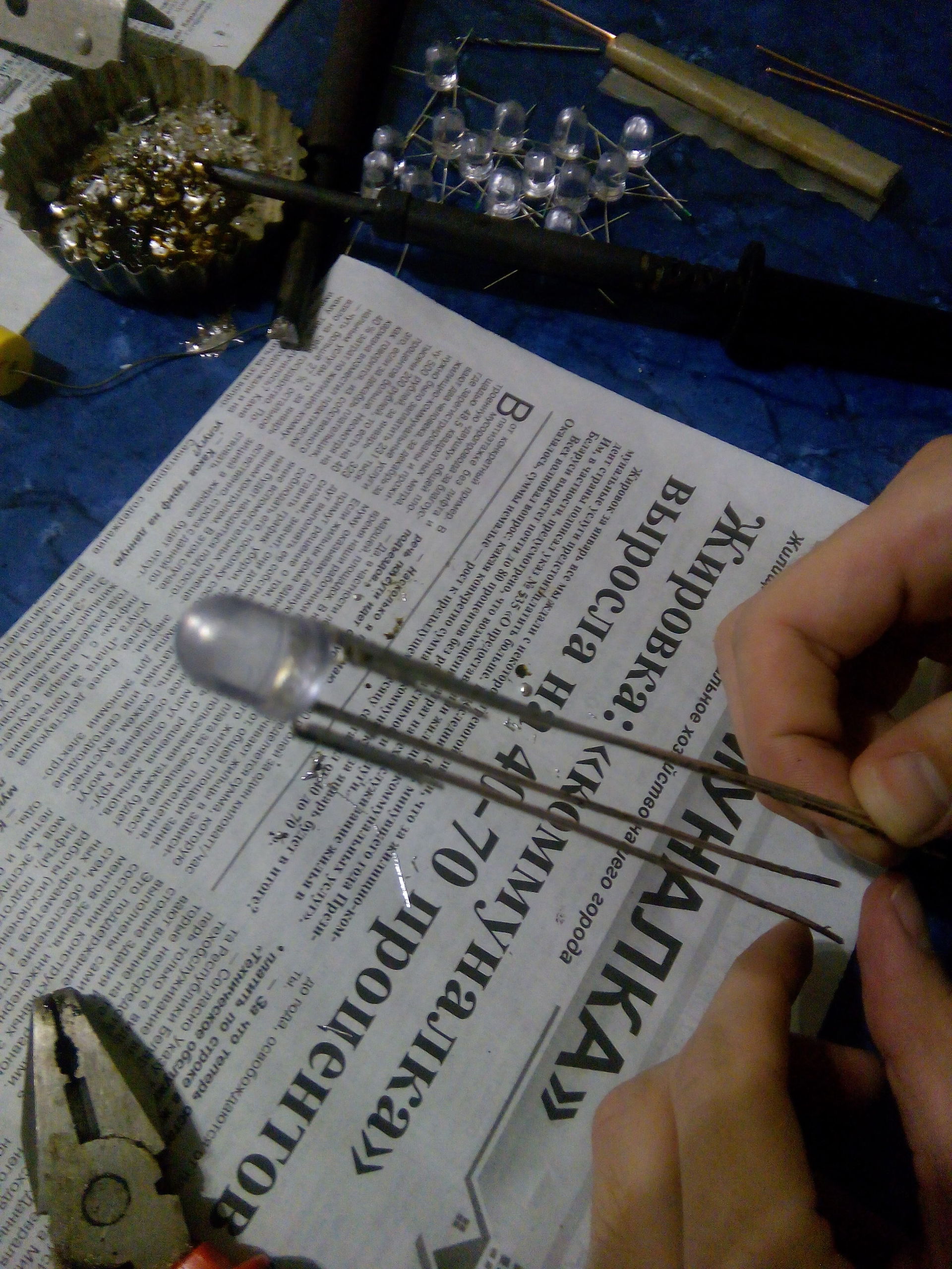
Before connecting the LEDs into the column, it is necessary to bend the legs in each of the four LEDs so that each leg is from the adjacent 90 °.
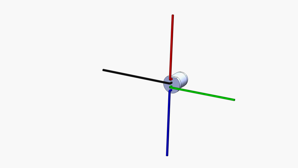
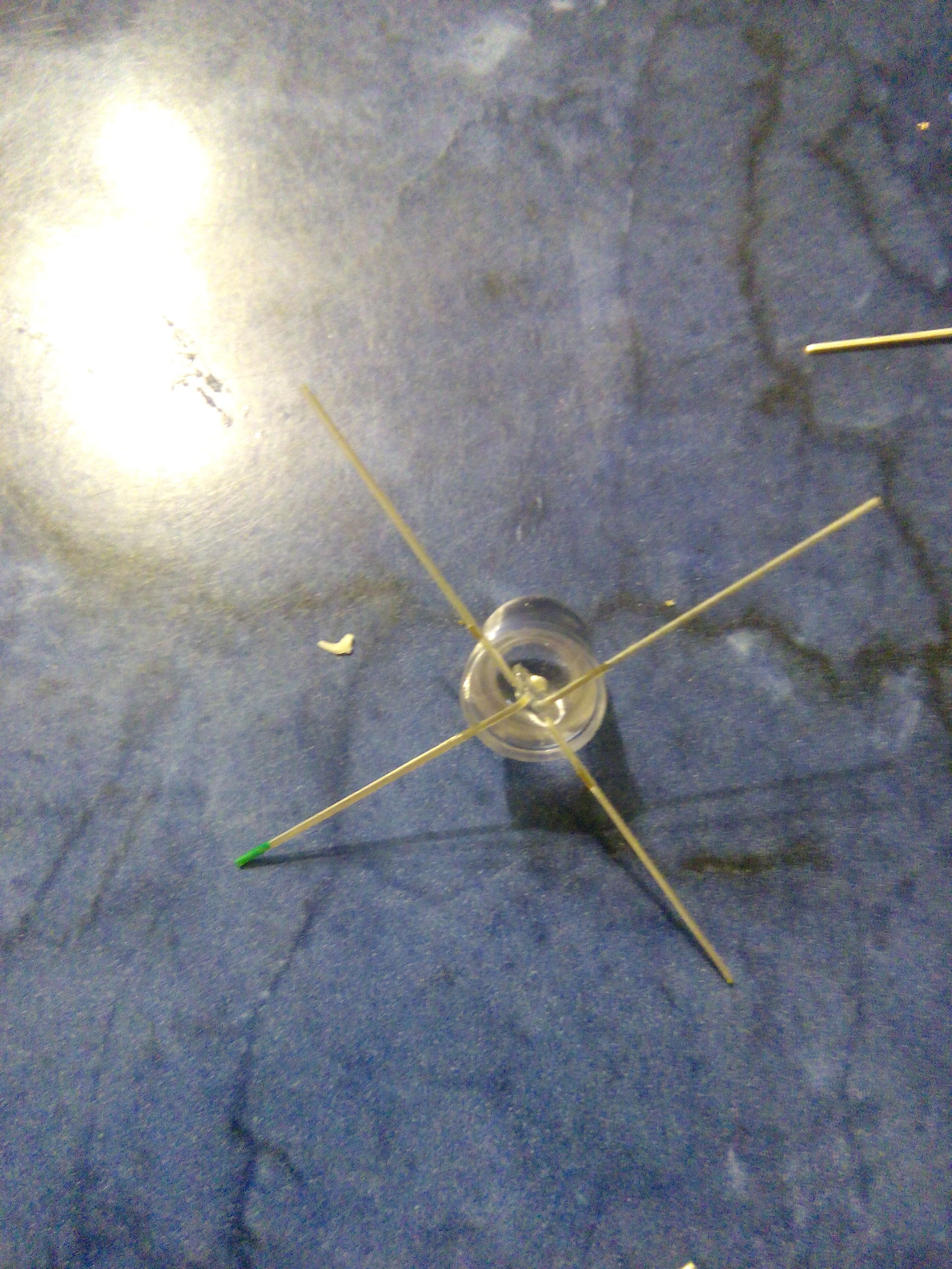
Then each of the LEDs must be rotated alternately by 90 ° (each subsequent should be rotated 90 ° clockwise relative to the previous one). You can pre-mark one of the legs (we have it marked with green varnish) so as not to get confused.
We connect our LEDs in a column. After connecting the LEDs, cut off the protruding ends of the legs.
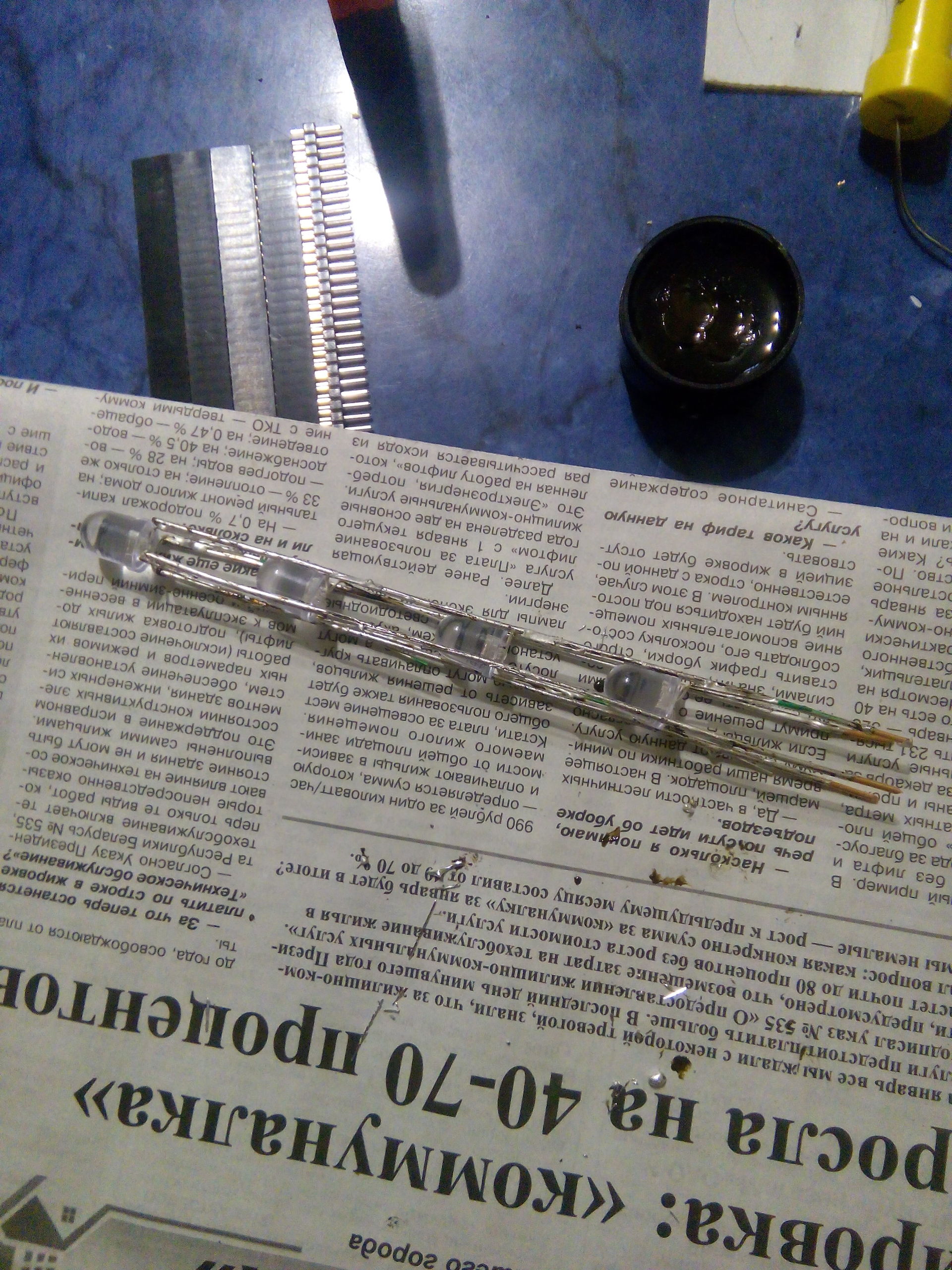
The remaining 15 columns are collected in the same way.
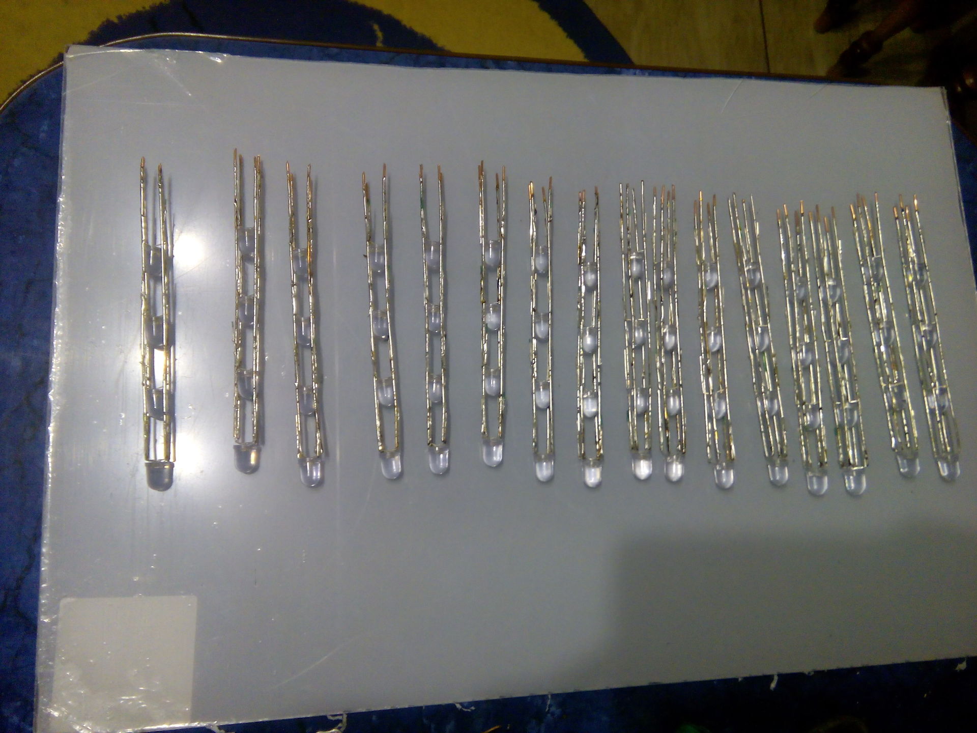
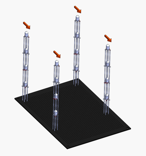
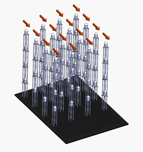
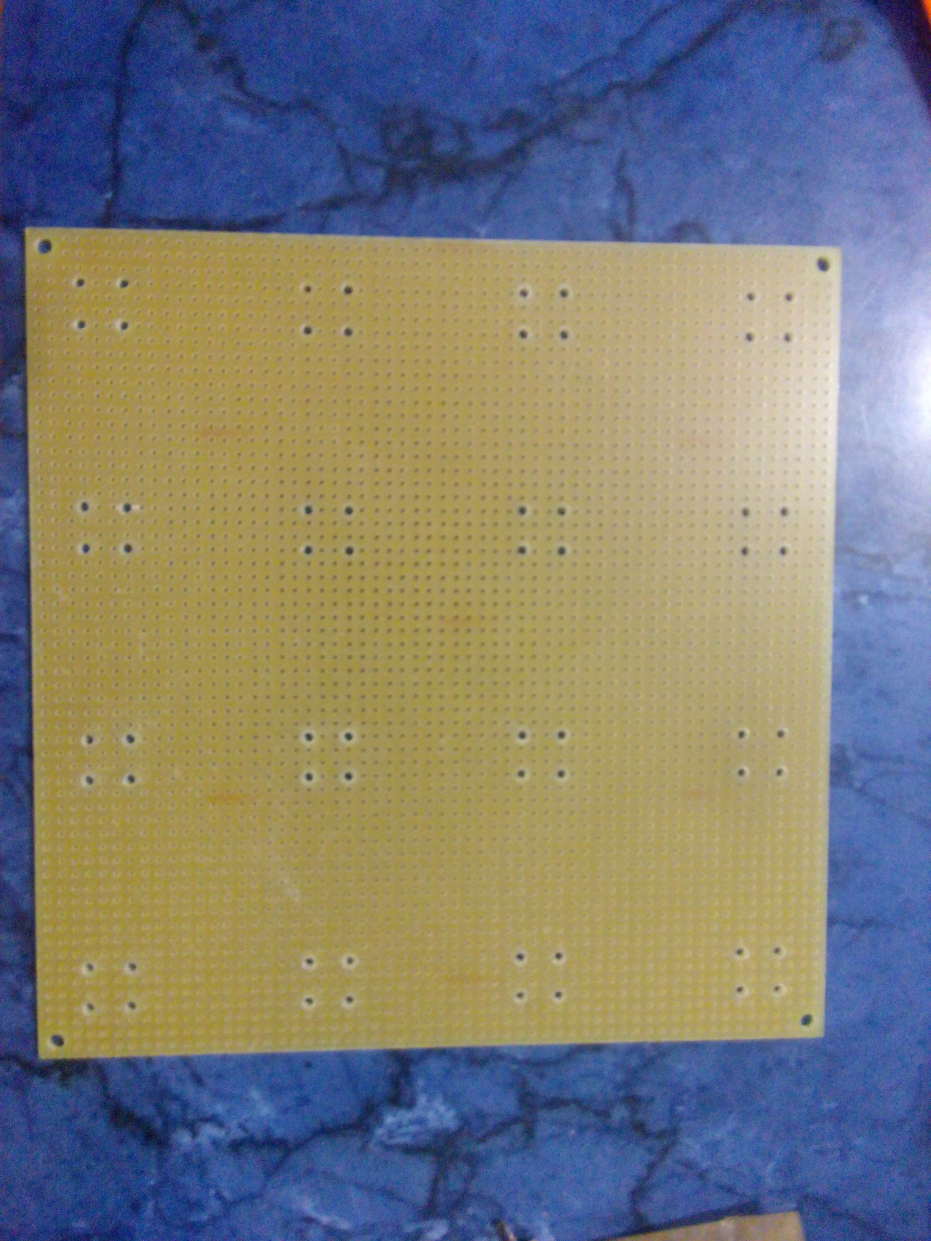
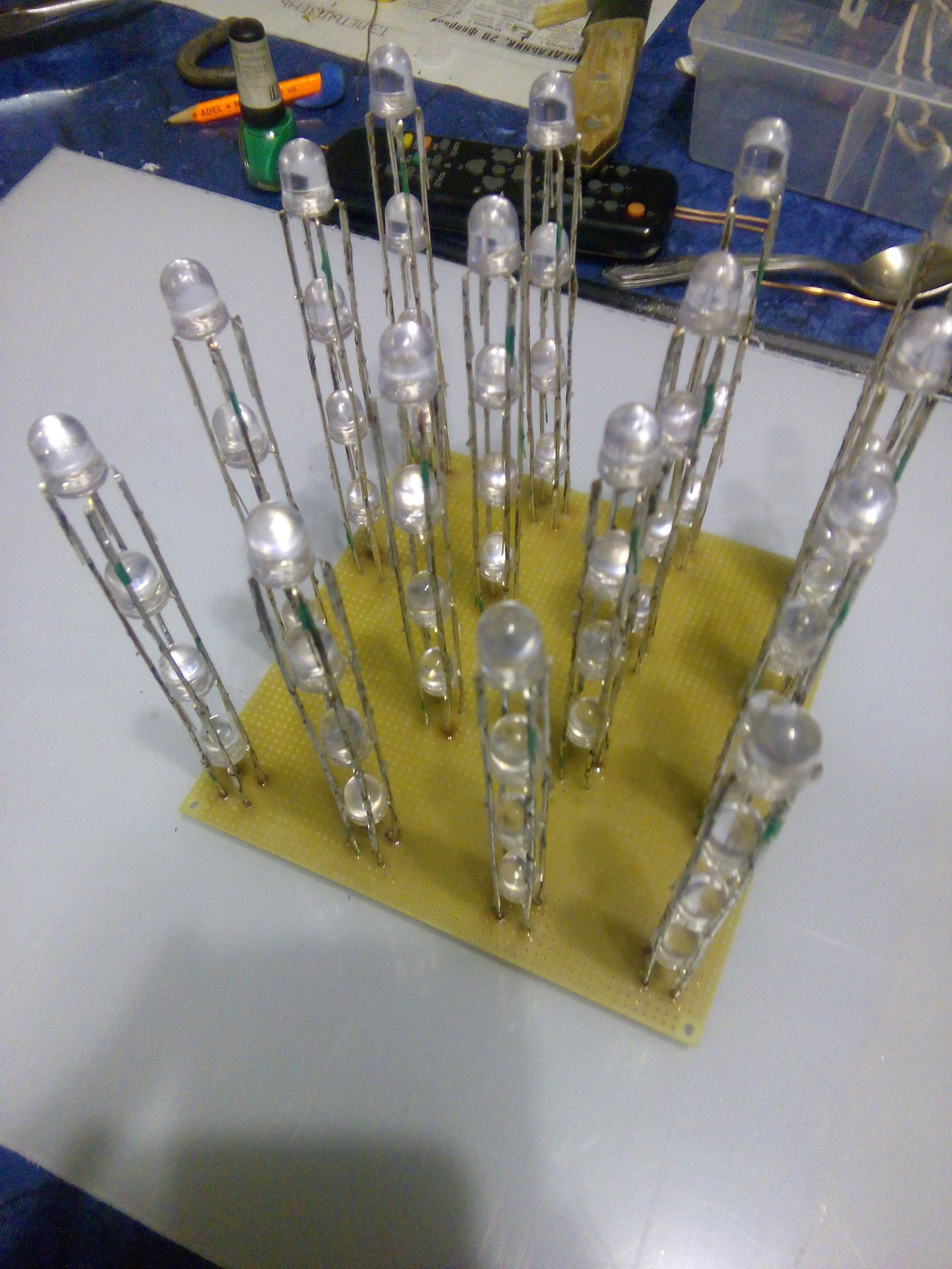
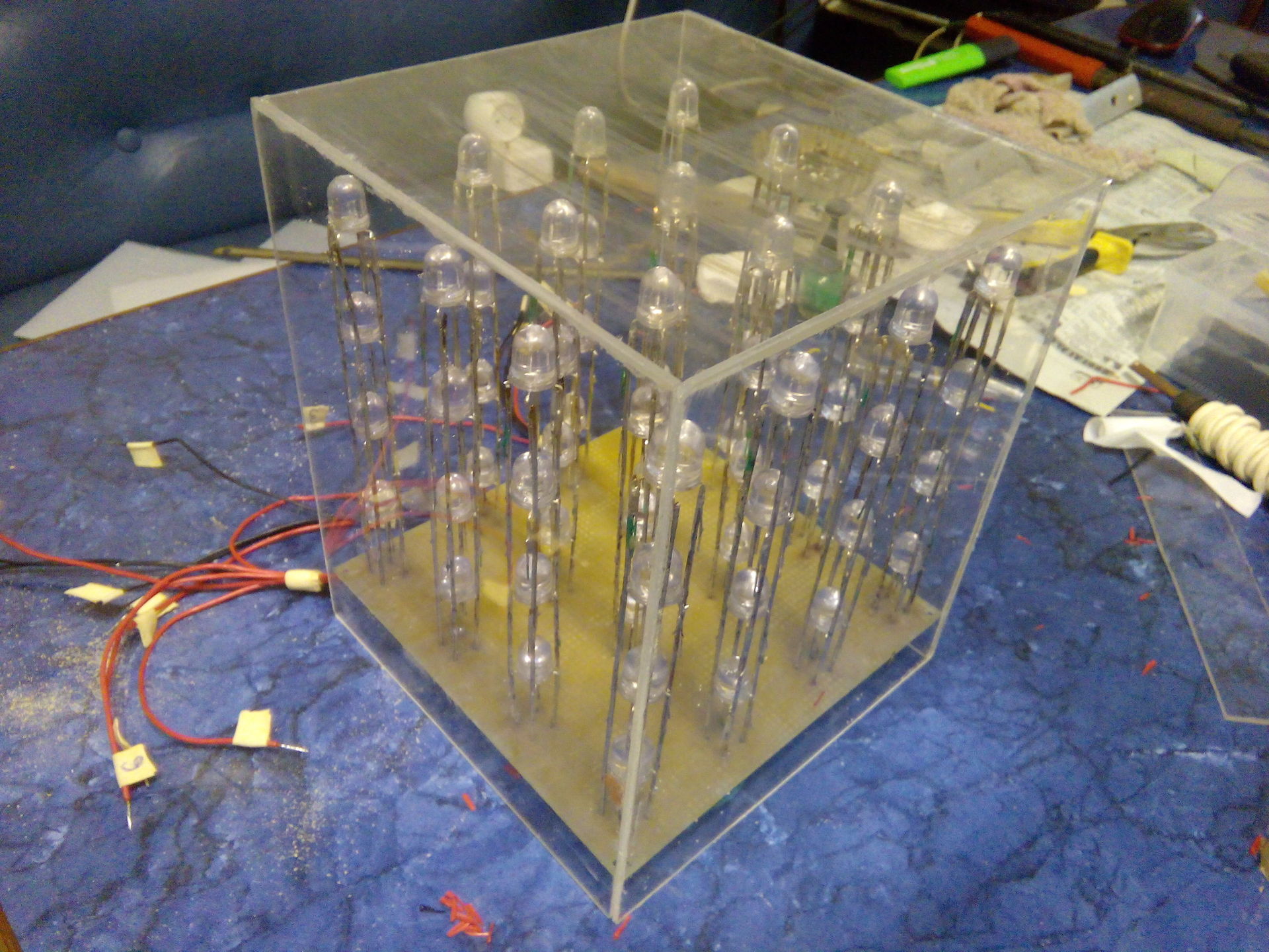
The columns are placed on the board at the same distance from each other, thus forming a cube with a side equal to 4 LEDs. All columns should be turned in the same direction (here the preliminary marking of the “supporting” leg is very useful).
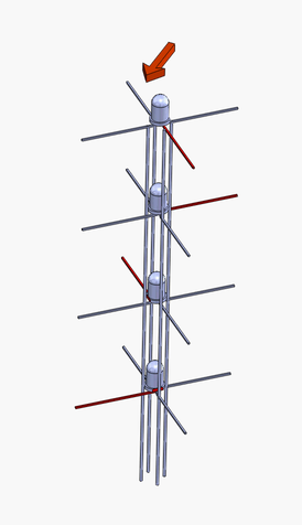
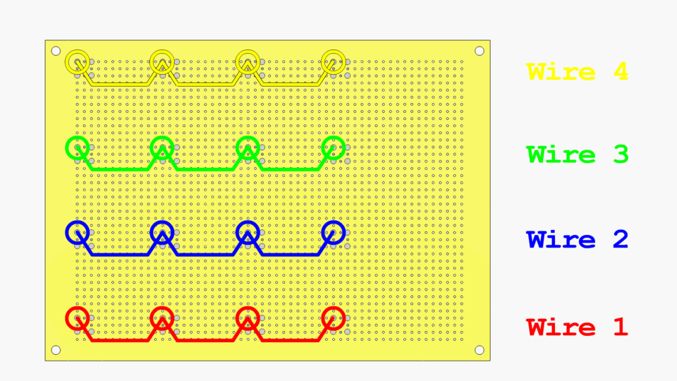
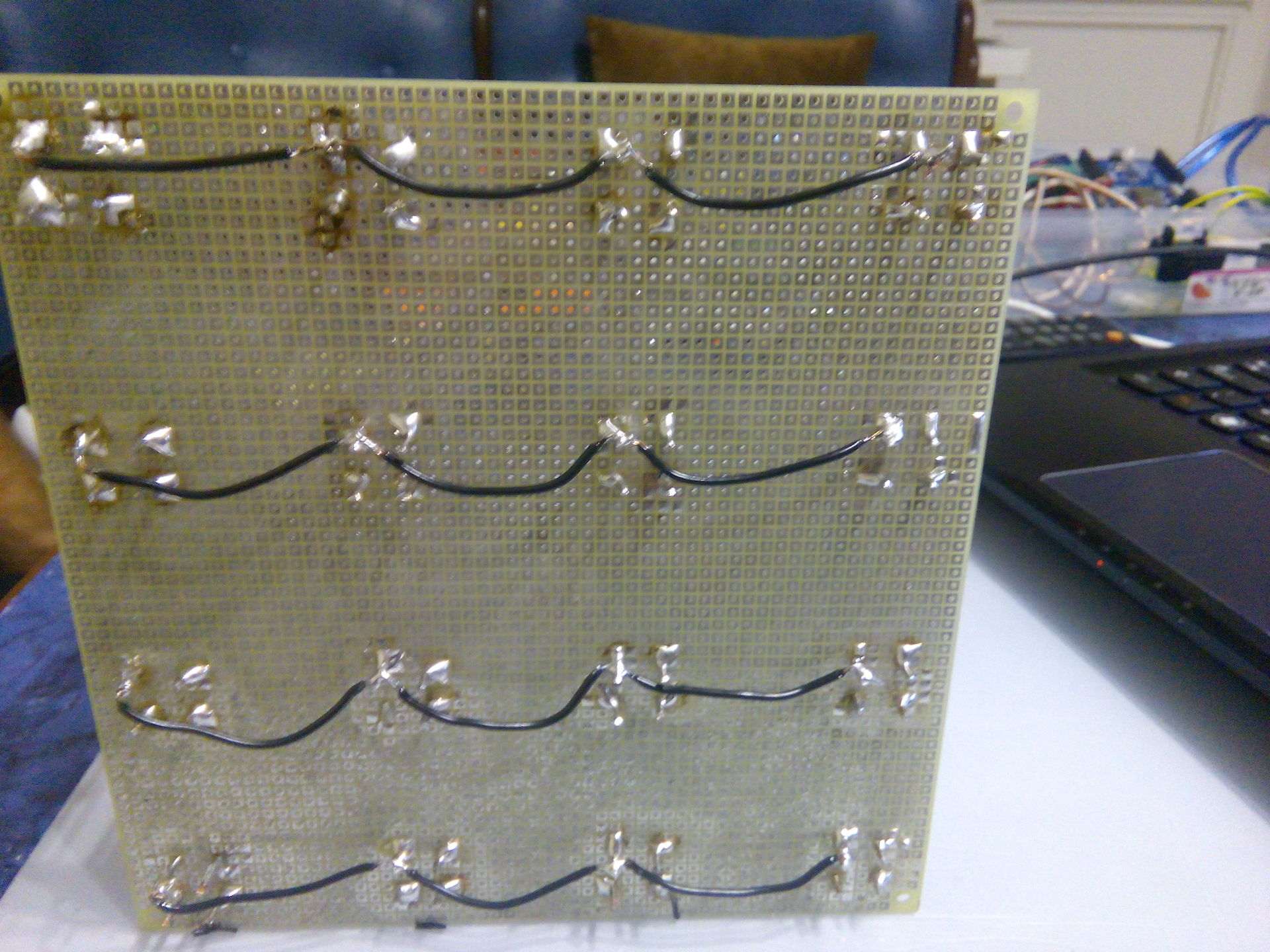
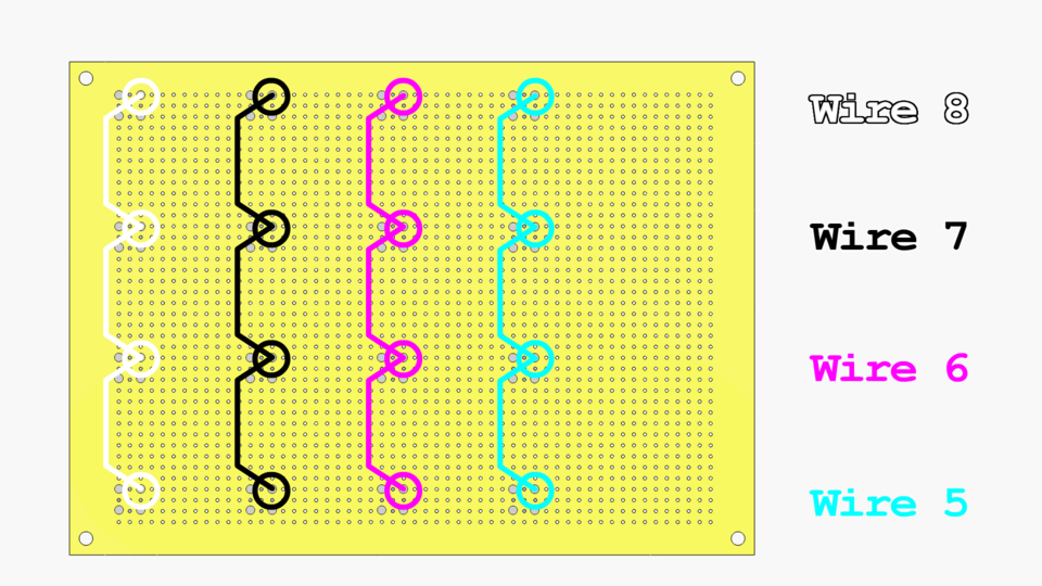
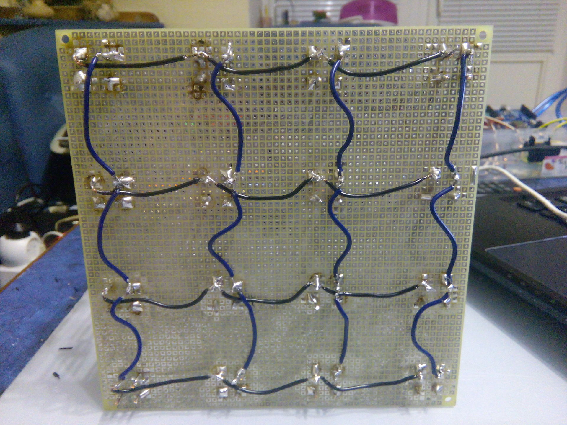
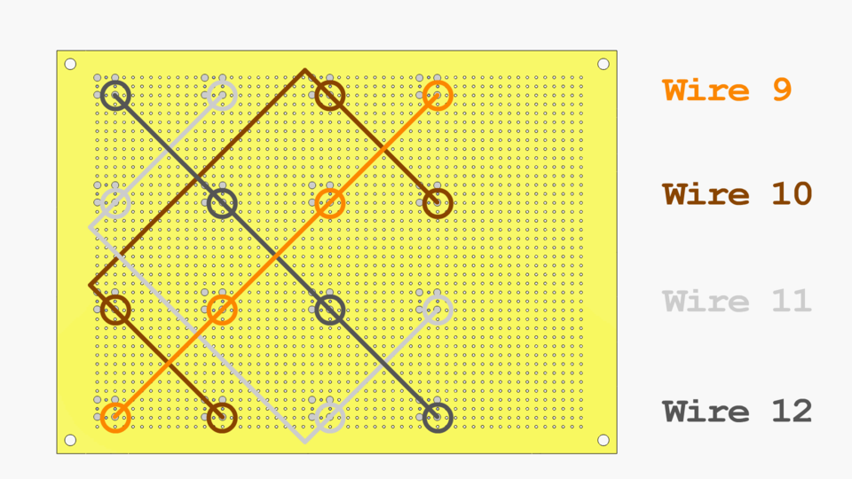
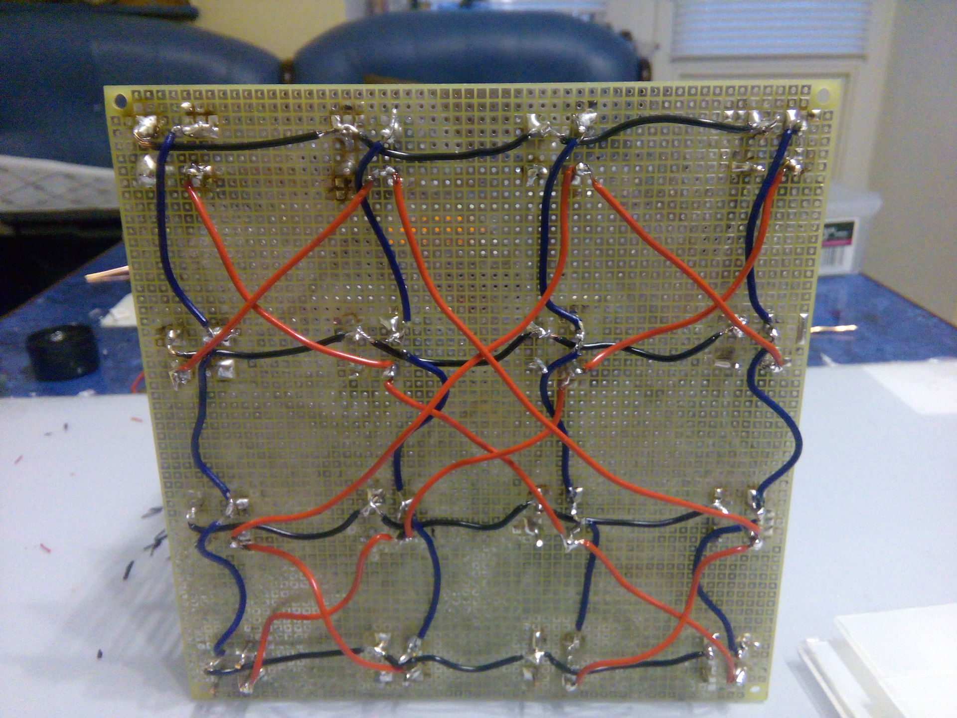
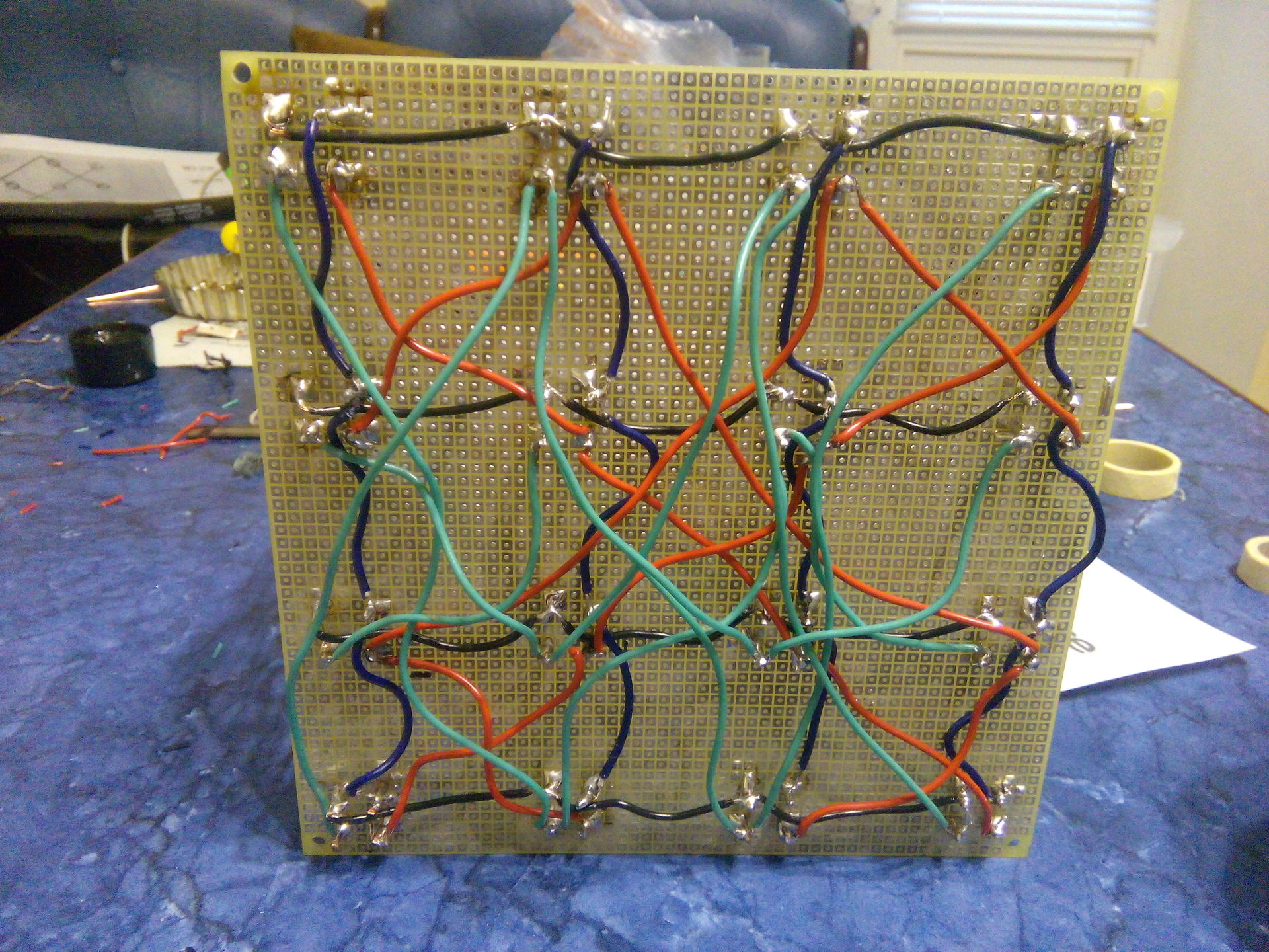
Overturn the structure and begin to connect the wires. A total of 16 wires, the connection was carried out in 4 stages.
It remains to connect to the Arduino - and you can start programming.
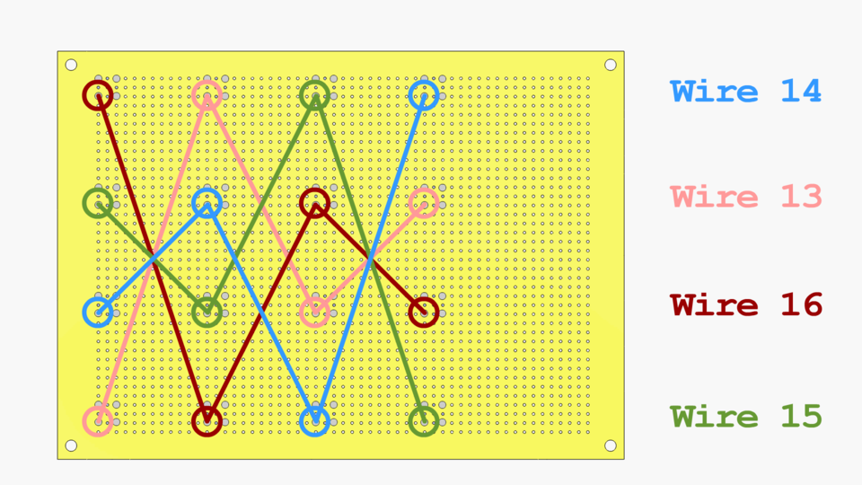
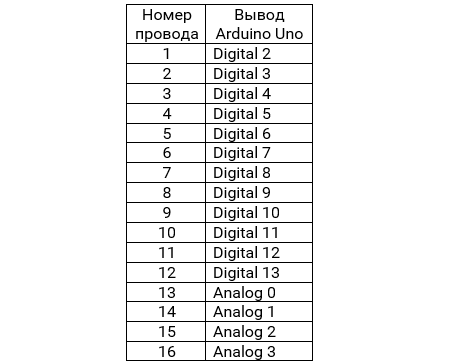
Charlickub authors have provided a cubeplex library for easy cube programming with Arduino. In order for this library to be used without modifications, it is necessary to connect our wires in the following order (the numbering corresponds to the wires in the images from the previous section):
As mentioned above, the authors used the charlieplex library, which provides the drawLed () function, which takes the color and position of the LED in XYZ coordinates.
Messaging is implemented via serial I / O to the port through which the controller connects to the machine. Work with such events is implemented in Arduino through SerialEvent .
It is assumed that the cube will flash in time with the music. Accordingly, you can simplify the message format to one digit. The algorithm is as follows: as soon as the music analyzer "catches" the beat, the cube should completely catch fire. After that, the cube will slowly (layer by layer) go out. As soon as the analyzer hits the next clock cycle, the cube again fully fills up. That is, it is enough for the cube to transfer one digit: how many layers need to be highlighted at the moment. Also at each iteration we will randomly determine the new color.
The Minim library suite includes the BeatDetect class, which provides tools for determining the rhythm of music. In general, with the help of this library, it is extremely easy to connect to the sound receiving channel and perform its frequency analysis. For our purposes, the frequency rhythm method came up.
The code was tested on Ubuntu 15.10; The version of JRuby used by the authors is jruby 9.0.5.0. To run the script, you need to install Processing and connect the Minim library.
By means of PulseAudio, the visualizer was assigned audio output as audio input, i.e. we get the visualization of the whole sound that comes from the speakers. After recording the video was superimposed sound, which was played at the time of the creation of the video.
We managed to get a sound visualizer in conjunction with a PC. In the future, you can improve the algorithm for determining the rhythm (the standard means of determining the rhythm of the Minim library are far from ideal), you can also display information about frequencies on the cube. As you can see, the cube is simple to build and program; in addition, it involves a minimum of components.
References:
The authors
Victor Makoyed and Yevgeny Kunitsa, 3rd year students of the BSUIR VMSiS
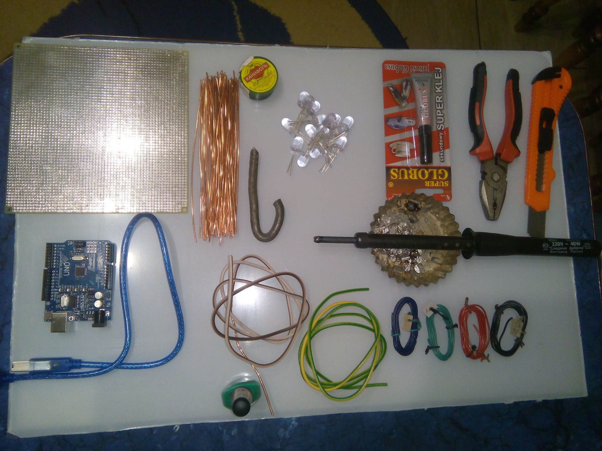
Training
Cube
In the study of such projects, a realization was discovered under the name “Charliecube” by authorship Asher Glick and Kevin Baker. This option is remarkable in that, unlike other implementations, it does not provide for counters, shift registers or any other components for building a cube for its subsequent programming and only involves 16 microcontroller pins (allowing you to address 64 LEDs). The basis of this implementation is the LED display design called "Charliplexing".
Charliplexing
The digital outputs of the microcontrollers have a three-valued logic: connected to the power supply, connected to the “ground” and not connected to anything. If we need to light the LED, it is necessary to apply "+" to X and "-" to "Y", only in this case it will be lit. If nothing is applied to Y, the LED will not light up. More information about the method can be found in the article of the same name on Wikipedia , below is a description of the work specifically in our case.
')
LED column diagram
Suppose we want to turn on LED1 in green. If you follow the blue line, you can see that you need to submit a “+” to input 1. Following the red line, we understand that you need to submit “-” to input 3. Nothing is given to the other inputs.
Visualization
It was decided that the entire analysis of the music will be performed on a PC connected to the cube. The basic idea: the PC analyzes the sound recording channel, converts the sound into frequency information and transmits data about the rhythm of the music to the Arduino. The microcontroller further highlights certain LEDs based on this information.
Since the authors of the project have a lot of experience with Ruby, in the framework of the project I wanted to resort to this particular programming language. An article by David Guttman describing the visualization of sound on JRuby using the ruby-processing heme and the Minim java library was discovered. The found article was taken as the basis for writing a visualizer.
Assembly
We collect a column
Before connecting the LEDs into the column, it is necessary to bend the legs in each of the four LEDs so that each leg is from the adjacent 90 °.
Then each of the LEDs must be rotated alternately by 90 ° (each subsequent should be rotated 90 ° clockwise relative to the previous one). You can pre-mark one of the legs (we have it marked with green varnish) so as not to get confused.
We connect our LEDs in a column. After connecting the LEDs, cut off the protruding ends of the legs.
Place the posts
The remaining 15 columns are collected in the same way.
The columns are placed on the board at the same distance from each other, thus forming a cube with a side equal to 4 LEDs. All columns should be turned in the same direction (here the preliminary marking of the “supporting” leg is very useful).
We connect columns among themselves
Overturn the structure and begin to connect the wires. A total of 16 wires, the connection was carried out in 4 stages.
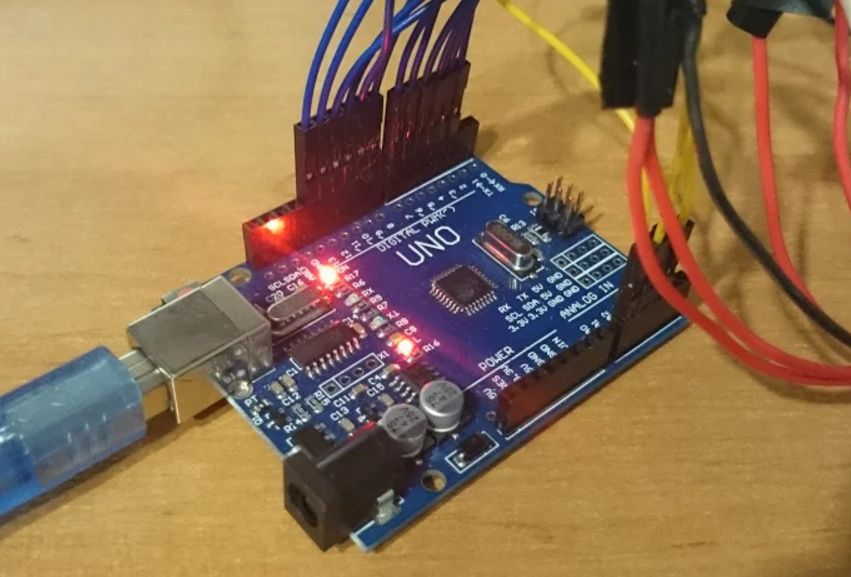
It remains to connect to the Arduino - and you can start programming.
We connect to Arduino
Charlickub authors have provided a cubeplex library for easy cube programming with Arduino. In order for this library to be used without modifications, it is necessary to connect our wires in the following order (the numbering corresponds to the wires in the images from the previous section):
We program Arduino
Basic functionality
As mentioned above, the authors used the charlieplex library, which provides the drawLed () function, which takes the color and position of the LED in XYZ coordinates.
Highlight the entire cube in red
#include "cubeplex.h" const int cubeSides = 4; void setup() { initCube(); } void loop() { for (int xpos = 0; xpos < cubeSides; xpos++) { for (int ypos = 0; ypos < cubeSides; ypos++) { for (int zpos = 0; zpos < cubeSides; zpos++) { drawLed(red, xpos, ypos, zpos); } } } } PC messaging
Messaging is implemented via serial I / O to the port through which the controller connects to the machine. Work with such events is implemented in Arduino through SerialEvent .
Selective cube highlighting with user input
#include "cubeplex.h" String inputString = ""; boolean stringComplete = false; // SerialEvent, inputString. // Enter, inputComplete loop(). int color = red; void setup() { Serial.begin(9600); inputString.reserve(200); initCube(); } void loop() { if (stringComplete) { Serial.println(inputString); drawString(inputString); resetBuffer(); inputString = ""; stringComplete = false; } } } void serialEvent() { while (Serial.available()) { char inChar = (char)Serial.read(); inputString += inChar; if (inChar == '\n') { stringComplete = true; } } } // ; . void resetBuffer() { flushBuffer(); clearBuffer(); } // . // - , . // "000001002003" { x: 0, y: 0 }. void drawString(String inputString) { int xpos = -1; int ypos = -1; int zpos = -1; for (int i = 0; inputString[i + 3]; i += 3) { xpos = charToInt(inputString[i]); ypos = charToInt(inputString[i + 1]); zpos = charToInt(inputString[i + 2]); drawLed(color, xpos, ypos, zpos); } } void charToInt(char value) { return (value - '0'); } Programming for light music
It is assumed that the cube will flash in time with the music. Accordingly, you can simplify the message format to one digit. The algorithm is as follows: as soon as the music analyzer "catches" the beat, the cube should completely catch fire. After that, the cube will slowly (layer by layer) go out. As soon as the analyzer hits the next clock cycle, the cube again fully fills up. That is, it is enough for the cube to transfer one digit: how many layers need to be highlighted at the moment. Also at each iteration we will randomly determine the new color.
Highlight the specified number of layers
void drawBeat(String inputString) { int height = charToInt(inputString[0]); int color = random(red, white); for (int xpos = 0; xpos < cubeSides; xpos++) { for (int ypos = 0; ypos < cubeSides; ypos++) { for (int zpos = 0; zpos < height; zpos++) { drawLed(color, xpos, ypos, zpos); } } } } Sound analysis on JRuby
The Minim library suite includes the BeatDetect class, which provides tools for determining the rhythm of music. In general, with the help of this library, it is extremely easy to connect to the sound receiving channel and perform its frequency analysis. For our purposes, the frequency rhythm method came up.
The code was tested on Ubuntu 15.10; The version of JRuby used by the authors is jruby 9.0.5.0. To run the script, you need to install Processing and connect the Minim library.
Rhythm analysis
require 'ruby-processing' require_relative 'translator' require_relative 'serial_writer' class SoundProcessor < Processing::App load_library "minim" import "ddf.minim" import "ddf.minim.analysis" def setup @minim = Minim.new self @input = @minim.get_line_in @beat = BeatDetect.new @input.mix.size, 44100 @beat_value = 0.001 @beat.set_sensitivity 300 end def draw process_beat SerialWriter.instance.write(Translator.instance.translate(@beat_value)) end private def process_beat @beat.detect @input.mix @beat_value = @beat.is_kick ? 1 : @beat_value * 0.95 end end SoundProcessor.new Demonstration of work
By means of PulseAudio, the visualizer was assigned audio output as audio input, i.e. we get the visualization of the whole sound that comes from the speakers. After recording the video was superimposed sound, which was played at the time of the creation of the video.
Episode
We managed to get a sound visualizer in conjunction with a PC. In the future, you can improve the algorithm for determining the rhythm (the standard means of determining the rhythm of the Minim library are far from ideal), you can also display information about frequencies on the cube. As you can see, the cube is simple to build and program; in addition, it involves a minimum of components.
References:
- Charliecube - Asher Glick
- Charliplexing - Wikipedia
- Create a Music Visualizer in 7 Steps with Ruby - David Guttman
- Code for Arduino
- Visualizer code
The authors
Victor Makoyed and Yevgeny Kunitsa, 3rd year students of the BSUIR VMSiS
Source: https://habr.com/ru/post/395475/
All Articles