Semi-automatic drilling complex for printed circuit boards for arduino and python

Foreword
Currently, amateur practices have mastered a wide variety of methods for manufacturing printed circuit boards, from the simplest “ironing” technologies using laser printer prints to high-precision ones using film photoresist. At the same time, drilling of printed circuit boards is carried out manually or with the use of the simplest devices. So we thought, why not try to automate this process a little and make a machine that will drill holes in printed circuit boards automatically. Interested invite under cat.
Concept
Before proceeding to the manufacture of the machine, you need to think about many details. The complexity of the machine is high, the budget is small, the correction of some stocks may be delayed for a long time. Simply put, the cost of fixing a bug is big.
To simplify the device a bit, we decided that the printed circuit board to be processed would only move along the conventional X axis (along the machine body), while the drill itself would move along the Y axis. The drill and the board will move using stepper motors driven by the Arduino. Commands on the Arduino will be sent via an emulated semi-user interface from the client application, where the user will specify the points to be drilled.
Device Development
Making a milling cutter implies a large amount of work on the mechanical part. It was here that we ran into most of the problems and spent most of the time on it. On the software side, it was necessary to develop a firmware for the device that implements a minimal set of simple commands to control the machine, and a client application that allows you to create and execute a drilling program.
Mechanics
To move along the X and Y axes, pairs of screw - nut with thread are used. The use of a thread with a pitch of 1 mm is convenient in that one turn of the screw moves 1 mm. Considering that for applied stepper motors, 48 pulses per shaft revolution are required, the displacement step along X and along the Z axis was approximately 0.02 mm. There are many factors due to which the step size may differ from the calculated one. For example, screw irregularities, inaccuracies in the manufacture of parts, play of some elements, etc. Therefore, in the design of the machine, some measures were taken to reduce the influence of the most significant of them (additional homemade polymer nuts; floating fit of electric motors, allowing them to move within certain limits during operation). The carriages for the board and the drilling unit move along the X and Y axes, respectively, along guides from the DIN rail. Together the contact carriage for the board and guides to reduce friction applied fluoroplastic tape.
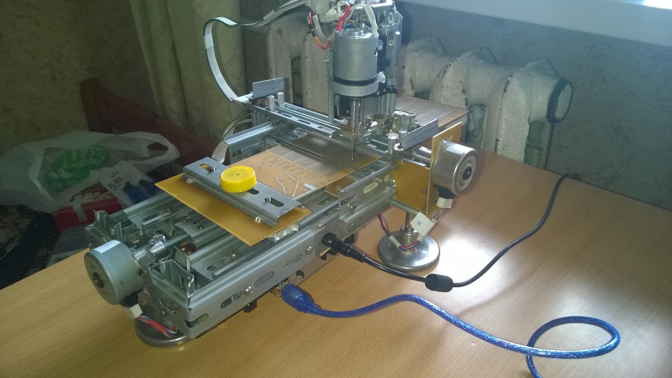
For the Z axis, an existing low-power electric motor with an integrated gearbox is used. In this regard, when using a pair of screw - nut turns out too slow movement. Since high accuracy in this case is not required, instead, carriage movement is used, with an electric motor mounted on it, along a fixedly attached nylon thread. To prevent breakage of the drill, as well as to determine the distance to the board, for example, when drilling is replaced by milling, the drilling mechanism is connected to the carriage by a spring mechanism with the ability to adjust the spring force. If the drill touches the plate surface, the drilling mechanism will stop and the carriage will continue moving downward, compressing the spring. A slight compression of the spring will cause the microswitch of the stop to open and send the corresponding signal to the electrical part of the machine.

Movement on all axes is limited by limit switches, giving the appropriate electrical signals. Since used drills can have different lengths; adjustment of the position of the upper (discrete) and lower (smoothly) limit switches is provided. For other limit switches, position adjustment is not provided.
Electronics
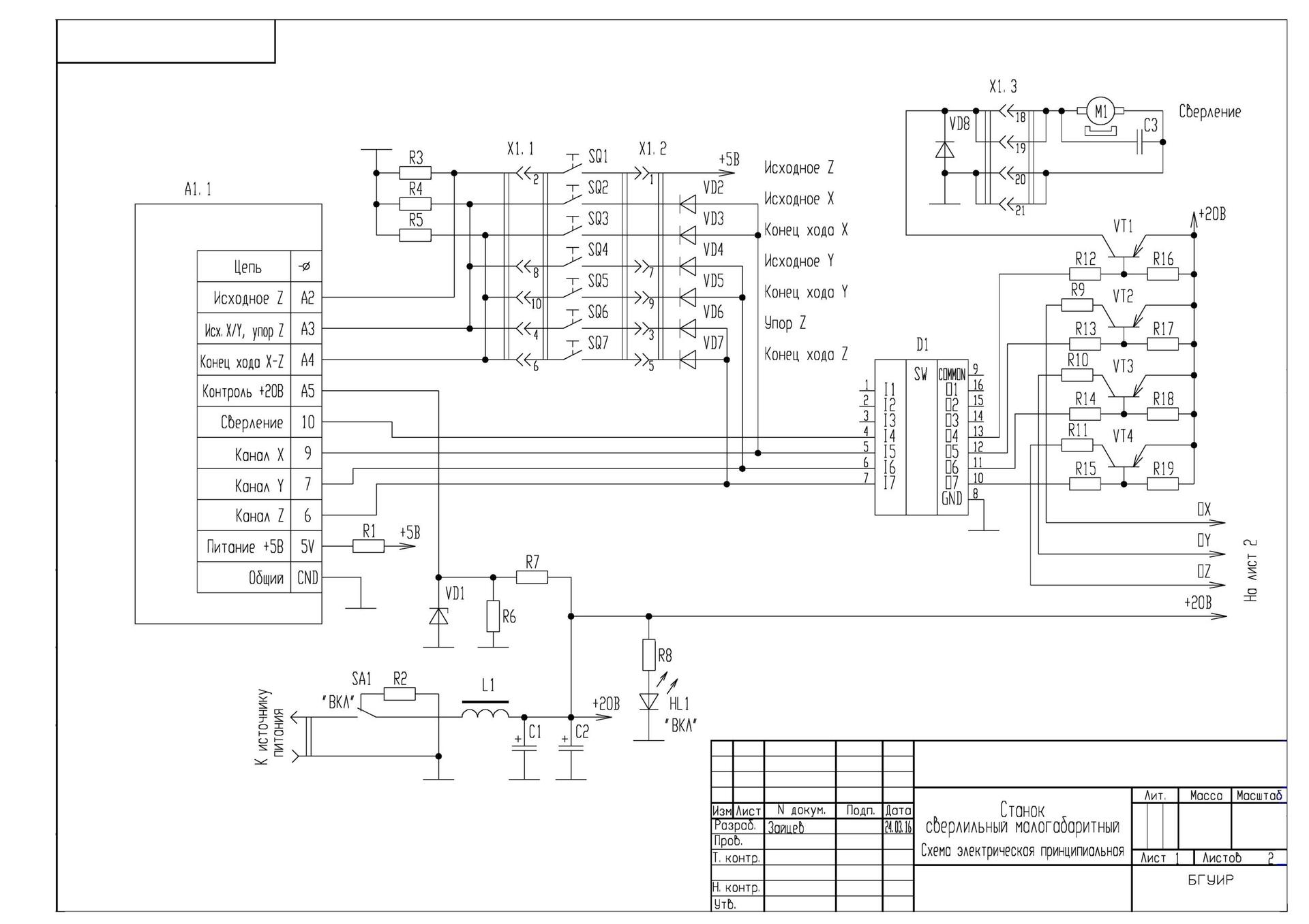
The Arduino board is powered directly from the USB port. The voltage of 5 V from the Arduino board is used in the machine to power the sensors.
To simplify the circuit and for electrical safety reasons, a ready-made external power supply from a laptop with an output power of 75 W (19 V, 3.9 A) was used to power the electric motors.
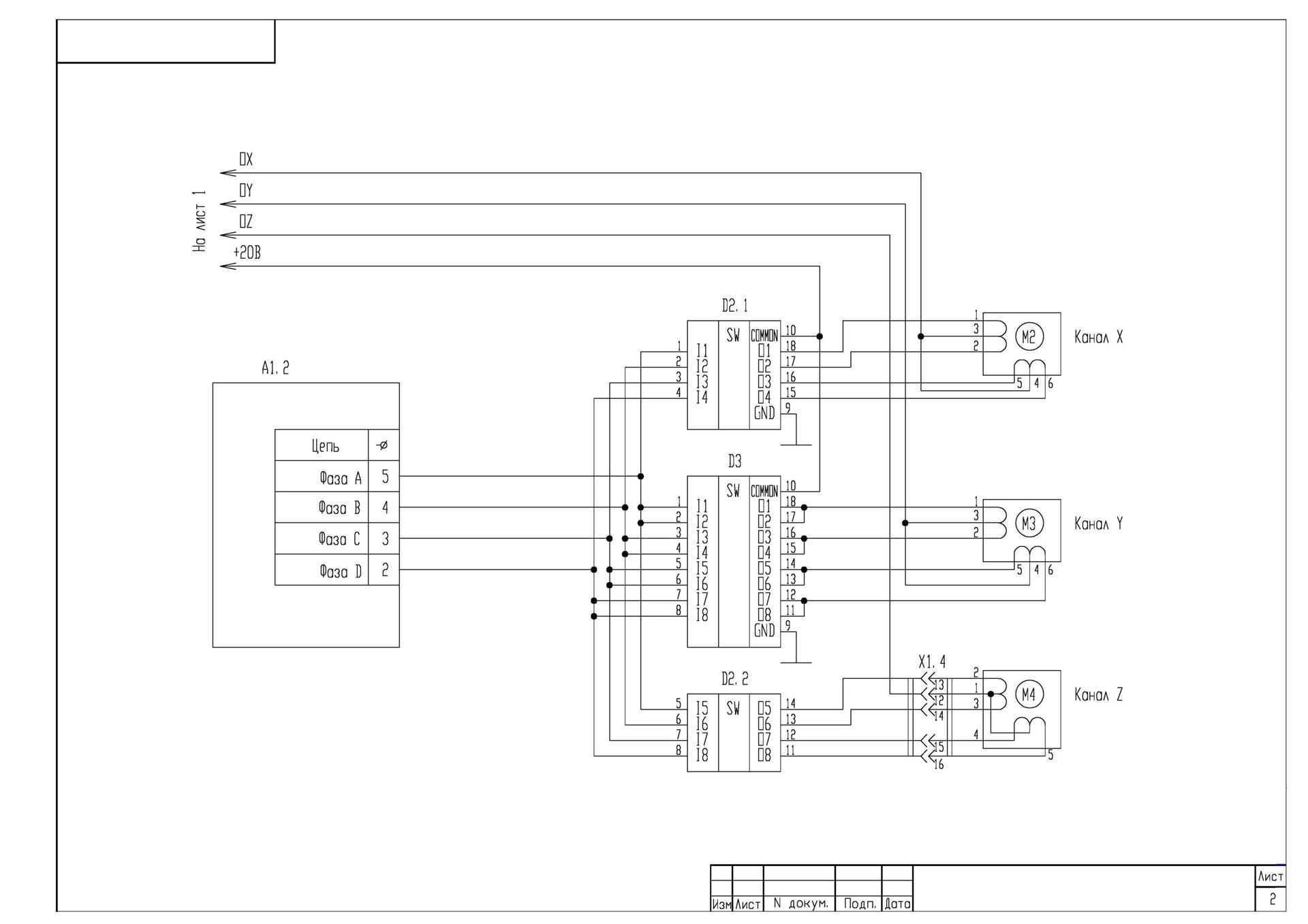
To connect stepper motors, typical driver chips (D2, D3) with keys on composite transistors and open collector pins are selected. A similar D1 chip is used to match the outputs of the Arduino board with transistor switches. Available electric motors are designed for different operating voltages. For their power supply from a single source, damping resistors R9 ... R11 were used. The operating current of the M3 motor exceeds the operating current of one channel of the selected chips, so two channels of the D3 chip connected in parallel are used to power each of its windings.

Drilling drive M1 has a working voltage range from 6 to 24 V and excess power and speed of rotation. To ensure the required drilling mode, a permanent signal is sent to the VT1 key, but a PWM with selected parameters.
The state of the SB2 ... SB7 limit switches is important only while moving along a certain axis, therefore, to save the controller I / O, they are pairwise combined into a 3x2 matrix and connected between the input and the output of one of the control channels. When moving along the X and Y axes, the drill should be in the upper position to avoid breakage. On this basis, the limit switch SB1 is connected directly between the input and the 5V source, for control during any of the movements.
Software development
The device firmware was written in the Arduino language, and the client application was developed in Python for GNU / Linux.
Device firmware
A simple machine control protocol was developed. The format of the command is: <method>: [arg1 [arg2 [...]]]\n . After the command is executed, the machine returns the result. This is usually 0 or 1 (False or True).
Command system:
| Team | Command description | Return values |
|---|---|---|
| connect: | The command is carried out in 2 stages. Upon receipt, the machine immediately sends res: 1 in response. this allows the client application to determine which particular COM port the machine is connected to. Then the machine initiates the start-up procedure, after which it sends ready: 1 . | res: 1 + ready: 1 if successful; res: 1 + error: 1 in case of power failure | |
| touch: | Attempting to touch the board with a drill. | res: 1 when touched; res: 0 if the board is not detected |
| move: xy | Moves the drill to the specified coordinates | res: 1 on successful completion; res: 0 on error (coordinates are wrong; power failure during execution) |
| drill: xy | Moves the drill to set coordinates and drills a hole. | res: 1 on successful completion; res: 0 on error ( move command error; no board) |
| coords: | Returns the location of the drill. | res: xy |
Returned errors:
| Mistake | Error description |
|---|---|
error: 0 | Team not recognized |
error: 1 | No power |
When developing the firmware, attention was primarily paid to security. When executing any command, the machine follows the following rules:
- any commands except
connectshould be ignored if the start procedure has not been performed since the moment of activation (rollback of all axes and resetting the coordinates to zero) - It is forbidden to move along the X and Y axes with the drill lowered.
- it is necessary to immediately stop the movement on the axis when reaching the limit switch
error: 1must be returned if there is no power at the time of receiving the command related to the operation of the engines- in case of power failure, when executing a command related to engine operation, it is necessary to complete the command and return 0 (False)
Client application
Initially, it was planned to install a camera on the machine, with which it would be possible to take pictures of the board and determine the points for drilling with OpenCV, however, finding small circles on a real etched board turned out to be quite a challenge, and acquiring a new camera is a bit expensive. Therefore, for the first time, we decided to limit ourselves to the fact that the user will set the necessary points for drilling on the board drawing, which is loaded into the application. A typical workflow is as follows:
- the user starts the application and specifies a picture (drawing of the board) for work
- points on drawing 2 any points
- switches to the point mode on the machine. In this mode, you can control the position of the drill, as well as touch the board. The user must consistently aim at each of the points indicated earlier in the drawing. This allows you to compare the coordinate systems of the drawing and the machine
- the user places points for drilling in the drawing
- the application makes a drilling program and starts controlling the machine
The module pyserial was used to communicate with the machine. When launched, the application receives a list of all available serial interfaces (/ dev / ttyACM *). The connect command is sent to each of the interfaces. If res: 1 is received in response, the machine is found.
GUI is implemented using PyQt5.
Conclusion
It is planned to add an automatic point recognition module for drilling to the client application. At the same time, after comparing the coordinates, the application will automatically find points in the drawing, the user will only have to delete the erroneous and add unrecognized ones.
')
Source: https://habr.com/ru/post/395297/
All Articles