Sound from the picture. Optical synthesizer Look Modular
Hi GT!
June 4 in Moscow will host the next festival of music technology Synthposium . Fans of synthesizers will gather on it to twist knobs, collect patches, press keys and admire sounds.
We were also invited to do something cool for the festival.
And we assembled an analog optical synthesizer.
(Watch out for traffic!)


Do you know how to reproduce sound from a film in a movie theater? In the simplest version, the sound is recorded on the same film in the form of two tracks - the left and right channels. Here in this picture - the stereo sound on the left, in the form of two white tracks. There are still a lot of digital information next to it, but this is not about now.
The light passes through the film and enters the phototransistor .
If it is very rough, the phototransistor converts the photons that fall into it into electric current and amplifies it.
The more photons hit the transistor, the less its resistance, and, accordingly, less voltage at Vout . If the illumination of the phototransistor varies in the range of audible frequencies, then when you send a signal from Vout to an amplifier with a speaker, we will hear a sound.
')
I decided to make a synthesizer with the same effect.
I used the following line sensor as a pickup:

This sensor illuminates the space beneath the LED and receives the reflected light by the phototransistor. At the output, we obtain a voltage proportional to the brightness under the sensor. If anything, the sensitivity can be adjusted by the integrated potentiometer.
Now take some picture and motor:

Spinning the motor - the brightness under the sensor will start to change cyclically. This is the waveform I got from this image:

If we twist the picture with a frequency not in a pair of hertz, but, say, somewhere in 440 Hz, we will get a note for the first octave. With a timbre that resembles the timbre of a periodic function. And if you take the picture more difficult? Get the timbre ... more difficult.
Our analog synthesizer should be able to rotate the image with the frequency of the note that came to it via MIDI. I wanted to capture at least the fifth octave in pitch. In accordance with the table of notes and frequencies, this is somewhere under 1 kHz.
So we need a very nimble motor, which can turn around 1000 times per second. I took a suitable one from a radio-controlled helicopter.

I must say - he howled like a Bulgarian. In addition, he cut paper on his fingers and scattered pictures in different directions, like ninjas - shurikens. After another shot, the office rebelled. I had to be content with the good old quiet CD-drive.

The CD drive has its own driver chip which controls the engine. It is enough to solder to the necessary pins, and we will be able to control the speed of rotation of the engine and find out the frequency with which it rotates. In my case it was the M63044FP chip. I did not find a datasheet for it. But I found a datasheet for a very similar M63022FP . She was different pinout, so I had to look for the right legs at random.

The rotation speed is regulated by applying an analog voltage to the SPIN pin. I took a 220 Ohm resistor, soldered wiring to it. Turned on the power. I poked one end of the resistor into the 5 V bus of the CD drive, and I wired all the microchip's legs through the wiring. Upon contact with the right leg, the slider started. I'm surprised, but nothing burned in the process.
To control the rotational speed, it remains to find the pin OSC, which produces a square wave when switching the motor windings. Then I had to uncover an oscilloscope, start the engine and search.
Easy further. We follow the path from the legs and are looking for - where to solder?
At the same time, solder the LM7805 to a pin of 5V power supply in order to power the whole structure with a single voltage source of 12 V.
Soldered wiring to SPIN, OSC. And the earth, so that all devices were on the same wavelength:

The picture is clickable
The regulator, by the way, is very hot during operation. Get burned quite real. But during DIY-binge, such things do not bother me much. Works.
The engine from the CD-drive allowed to accelerate the image to 250 Hz. Therefore, a small octave is a maximum. Nothing can be done, in this case we have a bass monophonic analog synthesizer. Just like Moog Minitour .
Sound synthesizer is determined, among other things, low-frequency modulation of the volume and / or filter cutoff frequency ( ADSR envelope ). I also wanted such a thing in my synthesizer. How to do it?
Watch your hands:
Since the constant component of the signal from our pickup is cut off by the input capacitor of the amplifier, the volume of the sound in our case is the difference between the darkest and lightest parts of the picture. The farther away the sensor is from the image, the smaller this difference is, as less and less photonics reach the phototransistor from the brightest parts. The closer the sensor - the greater this difference, and therefore the greater the amplitude of the signal.
If the sensor is brought very close to the picture, in bright places the transistor will open to its fullest. Smooth parts of the sound wave will be cut from this. The result is a kind of distortion effect with a sharp increase in the number of high harmonics. It will greatly decorate the sound. Therefore, I put the sensor on the servo.

With the NoteOn MIDI event, it will quickly get closer to the picture, the closer the speed of pressing the MIDI-keyboard key (velocity). Over time, you can slowly lift the sensor. Here is such a mechanical ADSR.
The analog path must not intersect with the power and digital part, so as not to catch interference from there. So I just soldered another LM7805 with electrolytic and ceramic capacitors in Troyka Shield. I sent 12 V to the input with Vin , and sent the output to the line sensor and the audio amplifier module. The output of the line sensor is soldered directly to the input of the amplifier. Everything, now we have a separate analog power circuit.


MIDI input had to collective farm optocoupler 6N137 . It was possible to do with one transistor with a pair of resistors, but not according to the standard.

Building constructs with the # Structure is easy. From electronics we will have:
All these parts have a special snap-in from # Structure, so the assembly is:
In order to attach a picture on the shaft of the motor you need some kind of fasteners. I tried to glue the picture directly onto the spindle with double-sided tape, but the pictures quickly flew away. Yes, and change them uncomfortable.
It is good that there is such a mount in the CD drive itself. This circle lives in the top cover of the CD-drive, and fixes the CDs on the spindle. It has a magnet, so it is easy to remove it from the spindle and place it back. Well, the picture can be glued to double sided tape already to him.

Here you can also see a super-life hacking to reduce portamento time when the frequency changes down. Motor from the CD-drive can not brake. Therefore, the portamento down becomes so indecently long that it is already a straight glissando of some kind. Therefore, the brake was added from the folded paper.
Finishing touch. The electronics are simply put in a cd drive. If anything, at any time you can pull.


Code available on github.com
We, as always, recorded a video about this project. You can listen to how this synthesizer sounds from 10:36.
It turned out to be funny with servo envelopes, but still it would be better to do without mechanics for this purpose. The attack is too long. A sharp attack could be obtained if you use an incandescent lamp and PWM instead of a LED illumination.
In general, if it is interesting to play Look Modular, come on June 4th to Synthposium . I will be showing it at 16:30. I will bring a lot of paper, scissors, double-sided tape, magazines and markers. Let's experiment together.
That was the SinoPosium. Thanks to the organizers and participants, it was very interesting.
Thanks to everyone who experimented with the sound from the pictures with me. I did not expect such a warm reception. According to the results of the experiments, this preset sounds best of all:

Instagram videos from the event
June 4 in Moscow will host the next festival of music technology Synthposium . Fans of synthesizers will gather on it to twist knobs, collect patches, press keys and admire sounds.
We were also invited to do something cool for the festival.
And we assembled an analog optical synthesizer.
(Watch out for traffic!)
Now you will see the world's best analog synthesizer with moto-oh-oh-oor ... And MIDI.
OK OK. Hammond Organ was the best analog with a motor, but it definitely didn't have MIDI .
VCO
Do you know how to reproduce sound from a film in a movie theater? In the simplest version, the sound is recorded on the same film in the form of two tracks - the left and right channels. Here in this picture - the stereo sound on the left, in the form of two white tracks. There are still a lot of digital information next to it, but this is not about now.
The light passes through the film and enters the phototransistor .
If it is very rough, the phototransistor converts the photons that fall into it into electric current and amplifies it.
The more photons hit the transistor, the less its resistance, and, accordingly, less voltage at Vout . If the illumination of the phototransistor varies in the range of audible frequencies, then when you send a signal from Vout to an amplifier with a speaker, we will hear a sound.
')
I decided to make a synthesizer with the same effect.
I used the following line sensor as a pickup:
This sensor illuminates the space beneath the LED and receives the reflected light by the phototransistor. At the output, we obtain a voltage proportional to the brightness under the sensor. If anything, the sensitivity can be adjusted by the integrated potentiometer.
Now take some picture and motor:
Spinning the motor - the brightness under the sensor will start to change cyclically. This is the waveform I got from this image:
If we twist the picture with a frequency not in a pair of hertz, but, say, somewhere in 440 Hz, we will get a note for the first octave. With a timbre that resembles the timbre of a periodic function. And if you take the picture more difficult? Get the timbre ... more difficult.
Pitch
Our analog synthesizer should be able to rotate the image with the frequency of the note that came to it via MIDI. I wanted to capture at least the fifth octave in pitch. In accordance with the table of notes and frequencies, this is somewhere under 1 kHz.
So we need a very nimble motor, which can turn around 1000 times per second. I took a suitable one from a radio-controlled helicopter.
I must say - he howled like a Bulgarian. In addition, he cut paper on his fingers and scattered pictures in different directions, like ninjas - shurikens. After another shot, the office rebelled. I had to be content with the good old quiet CD-drive.
The CD drive has its own driver chip which controls the engine. It is enough to solder to the necessary pins, and we will be able to control the speed of rotation of the engine and find out the frequency with which it rotates. In my case it was the M63044FP chip. I did not find a datasheet for it. But I found a datasheet for a very similar M63022FP . She was different pinout, so I had to look for the right legs at random.
The rotation speed is regulated by applying an analog voltage to the SPIN pin. I took a 220 Ohm resistor, soldered wiring to it. Turned on the power. I poked one end of the resistor into the 5 V bus of the CD drive, and I wired all the microchip's legs through the wiring. Upon contact with the right leg, the slider started. I'm surprised, but nothing burned in the process.
To control the rotational speed, it remains to find the pin OSC, which produces a square wave when switching the motor windings. Then I had to uncover an oscilloscope, start the engine and search.
Easy further. We follow the path from the legs and are looking for - where to solder?
At the same time, solder the LM7805 to a pin of 5V power supply in order to power the whole structure with a single voltage source of 12 V.
Soldered wiring to SPIN, OSC. And the earth, so that all devices were on the same wavelength:
The picture is clickable
The regulator, by the way, is very hot during operation. Get burned quite real. But during DIY-binge, such things do not bother me much. Works.
The engine from the CD-drive allowed to accelerate the image to 250 Hz. Therefore, a small octave is a maximum. Nothing can be done, in this case we have a bass monophonic analog synthesizer. Just like Moog Minitour .
ADSR envelope
Sound synthesizer is determined, among other things, low-frequency modulation of the volume and / or filter cutoff frequency ( ADSR envelope ). I also wanted such a thing in my synthesizer. How to do it?
Watch your hands:
Since the constant component of the signal from our pickup is cut off by the input capacitor of the amplifier, the volume of the sound in our case is the difference between the darkest and lightest parts of the picture. The farther away the sensor is from the image, the smaller this difference is, as less and less photonics reach the phototransistor from the brightest parts. The closer the sensor - the greater this difference, and therefore the greater the amplitude of the signal.
If the sensor is brought very close to the picture, in bright places the transistor will open to its fullest. Smooth parts of the sound wave will be cut from this. The result is a kind of distortion effect with a sharp increase in the number of high harmonics. It will greatly decorate the sound. Therefore, I put the sensor on the servo.
With the NoteOn MIDI event, it will quickly get closer to the picture, the closer the speed of pressing the MIDI-keyboard key (velocity). Over time, you can slowly lift the sensor. Here is such a mechanical ADSR.
Analog path
The analog path must not intersect with the power and digital part, so as not to catch interference from there. So I just soldered another LM7805 with electrolytic and ceramic capacitors in Troyka Shield. I sent 12 V to the input with Vin , and sent the output to the line sensor and the audio amplifier module. The output of the line sensor is soldered directly to the input of the amplifier. Everything, now we have a separate analog power circuit.
MIDI
MIDI input had to collective farm optocoupler 6N137 . It was possible to do with one transistor with a pair of resistors, but not according to the standard.
Assembly
Electronics
Building constructs with the # Structure is easy. From electronics we will have:
- IskraJS - I'll finally try microcontroller javascript. In addition, it has a 12-bit DAC. It is just useful for controlling the leg of the SPIN motor driver;
- Troyka Shield - minimize soldering;
- Micro servo FS90 - mechanical ADSR;
- The line sensor is our pickup;
- Troyka-audio amplifier - the secret development of our KB. So far the deficit, but already in production;
- Troyka-MIDI IN - TODO our KB. I had to solder on the breadboard.
All these parts have a special snap-in from # Structure, so the assembly is:
- Dress up electronics in # Structure;
- Knife and ruler cut from the megapanel area for creativity to the size of the CD-drive;
- Close your eyes and stick the electronics wherever you want. I did it like this (clickable):

Mechanics
In order to attach a picture on the shaft of the motor you need some kind of fasteners. I tried to glue the picture directly onto the spindle with double-sided tape, but the pictures quickly flew away. Yes, and change them uncomfortable.
It is good that there is such a mount in the CD drive itself. This circle lives in the top cover of the CD-drive, and fixes the CDs on the spindle. It has a magnet, so it is easy to remove it from the spindle and place it back. Well, the picture can be glued to double sided tape already to him.
Here you can also see a super-life hacking to reduce portamento time when the frequency changes down. Motor from the CD-drive can not brake. Therefore, the portamento down becomes so indecently long that it is already a straight glissando of some kind. Therefore, the brake was added from the folded paper.
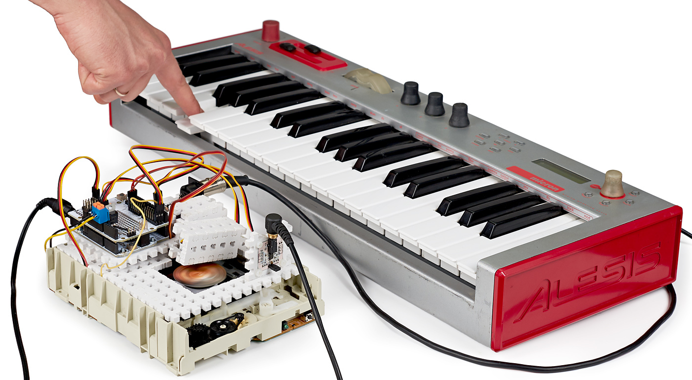
We put the electronics on the CD-drive
Finishing touch. The electronics are simply put in a cd drive. If anything, at any time you can pull.
Electrical connections
- MIDI-in - P0;
- SPIN - A4;
- OSC - P2;
- Micro servos - P13.
- CD Drive Power - Vin
Code
Code available on github.com
Demonstration
We, as always, recorded a video about this project. You can listen to how this synthesizer sounds from 10:36.
How can I improve?
It turned out to be funny with servo envelopes, but still it would be better to do without mechanics for this purpose. The attack is too long. A sharp attack could be obtained if you use an incandescent lamp and PWM instead of a LED illumination.
Epilogue
In general, if it is interesting to play Look Modular, come on June 4th to Synthposium . I will be showing it at 16:30. I will bring a lot of paper, scissors, double-sided tape, magazines and markers. Let's experiment together.
UPD
That was the SinoPosium. Thanks to the organizers and participants, it was very interesting.
Thanks to everyone who experimented with the sound from the pictures with me. I did not expect such a warm reception. According to the results of the experiments, this preset sounds best of all:
Instagram videos from the event
Source: https://habr.com/ru/post/394913/
All Articles