How to make a keyboard - Matrix
Posted by : Komar aka Michał Trybus; English-Russian translation : firerock
Original : blog.komar.be/how-to-make-a-keyboard-the-matrix
This is the first post in the keyboard series; I hope he will not be the last. I would like to end up with a course on making a keyboard from scratch. Today I will talk about digital I / O and keyboard matrixes. Arm yourself with elementary school knowledge from the field of electronics - and let's go.
And how are we going to do the matrix? And most importantly - why is it even needed? Well, the matter is that, basically, the physical limitations of microcontrollers, on the basis of which keyboards are built. The fact is that with an increase in the number of outputs in microcontrollers and programmable logic chips, their size also grows, which, in turn, entails an increase in energy consumption and opportunities, but the main thing is prices. As a result, you can choose either a cheap chip with a small performance (which suits you perfectly), but with a small number of inputs and outputs, or a more powerful chip, whose performance, however, greatly exceeds your requirements. But only this powerful chip will have enough pins to connect every button on the keyboard.
Over the decades, the practice of electronics has been developed with the help of various tricks to artificially expand the embedded communication capabilities of processors and controllers. One of these methods, which is well suited for mechanical contacts (buttons), is the creation of a matrix. To understand how it works, some basic knowledge is required. Before we continue, please refresh Ohm’s law .
')
To understand how digital electronics works, you need to learn two basic principles.
Principle one states that the process of communication within the scheme is not the transmission or receipt of something there. To ensure communication between the two devices, you simply interconnect their leads with an electrically conductive material. After that, it is assumed that the state of the material (voltage and current) at both its ends will be the same. In reality, this, of course, is not so, but for slow communications and short conductors, our assumption works perfectly. It turns out that sending and receiving information is in fact its sharing.
On the transmitter side, you simply change the electrical state of the conductor (by firing direct current into it, changing its potential), hoping that the receiver will be able to detect this change and understand it correctly.
It also follows from this principle that there is no dependence between the direction of communication and the direction of electric current. Many people mistakenly assume the opposite, and this prevents them from understanding how electronics work.
If you want to send a logic level "0", then usually the voltage at the output of the transmitter is lowered to 0 V, and a current begins to flow from the receiver to the transmitter so that the receiver can determine that the logic level corresponds to "0". (Whereas the reverse direction of the current would mean that somewhere in the circuit there is a negative potential - and this, as a rule, does not happen in digital electronics.) On the other hand, a voltage equal to the supply voltage is applied to transfer the logic level "1" and since this is, most often, the highest voltage in the circuit, there will be nothing left for the electric current to flow from the transmitter to the receiver.
Principle number two is that it is impossible to determine the state of the conductor without changing this state. It doesn't matter if you are going to measure voltage or current — in any case, it requires that electrons flow through your meter. The flow of electrons is the electric current, and once it flows, it means that in the node to which you connected for measurement, the currents and voltages have already changed (see Kirchhoff's laws ). From this it follows that if you need to “transfer” information by changing the state of the output electrically connected to another output, then this requires maintaining this state, and therefore, must comply with all requirements imposed by the receiver.
A mechanical button (and in this context, the word “mechanical” is not associated with the phrase “mechanical keyboard”) is just a pair of metal contacts that, when touching, electrically connect the two terminals. Of course, there are other types of switches, structurally more complex and having more conclusions, but they are not interesting to us, because they are not used in keyboards.
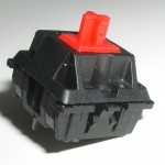
Cherry MX button. Image source: Deskthority wiki
Well, and how will we connect the button to the input of the microcontroller? In principle, any input can operate with two possible logical levels: "0" and "1". It is common practice to accept voltages close to 0 V as a logical zero, and voltages close to the supply voltage (usually 5 V or 3.3 V) as a logical unit. But the problem is that the mechanical button cannot control the voltage itself. It controls the current - that is, if we connect two nodes with different electric potential through the button, then the current between these nodes will flow if and only when the button is pressed.
But if we add a resistor, we can very easily convert current into voltage.

Pull Resistor Button
Take a look at this diagram. When the button is not pressed (the circuit is broken), the current does not flow through it, so the voltage at node “A” will be close to the supply voltage VCC (in fact, less than VCC by the voltage drop across the resistor equal to R • I). When the button is pressed (the circuit is closed), the current flows through the resistor to ground. Taking into account that the resistance of the closed button is very small (about hundreds of millimets), the voltage at the node “A” will be close to “0”.
In this configuration, the resistor is called pull-up, because it "pulls the voltage up" to the level of VCC. And without connecting to the power through the resistor, there would be no voltage at the node “A” at all (in this case, the output of the microcircuit is called “hanging in the air” or in a high-impedance state).
It should be noted that inside most modern microcontrollers already have pull-up resistors that can be quickly connected or disconnected using the program. So, the main way to connect a button with a microcontroller is the following: one button output - to the input of the microcontroller, another button output - to the ground. In this case, if the button is not pressed, then the microcontroller is fed "1", and if it is pressed, then "0". Perhaps this is contrary to intuition, but this method of connection is the most popular.
Please note that if we leave one of the pins of the button hanging in the air, that is, we don’t connect it anywhere, then this button will not work at all: do not press it, it will not affect the electrical status of the microcontroller. We still use this property when we make the matrix.
The basic principle of the keyboard matrix is the ability to connect to one input of the microcontroller more than one button.
With the help of transistors or properly configured outputs of the microcontroller, we can make the buttons connect to the earth one at a time, while the others will hang in the air. The remaining pins of each of the buttons are combined into one node and connected to the input of the microcontroller. I lowered the pull-up resistor, since we know that it is already present inside the microcontroller, in its input stage. We in turn “turn on” each button, connecting its pin number 1 to the ground via the corresponding output of the microcontroller, after which we can read the button state by removing the voltage from its pin number 2. Other buttons connected to the same input do not affect on his condition, because their conclusions number 1 are currently hanging in the air. The following diagram illustrates this idea.
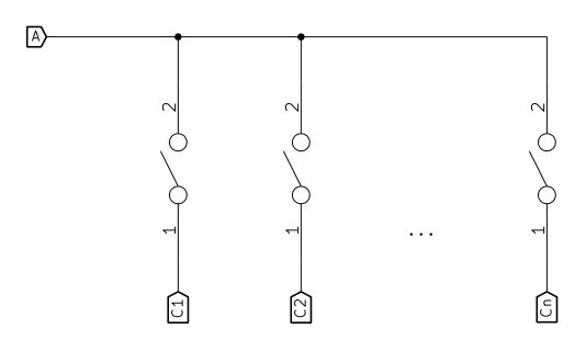
Many buttons, one input (node "A")
“A” is the only input of the microcontroller, and “C1” .. “Cn” is its outputs. A logical "0" is set at one of the outputs, that is, inside the chip, this contact is somehow connected to ground - therefore, the current will always flow to this contact (in accordance with the first basic principle). Now, when the button connected to this output is pressed, through it the input “A” will immediately “press” to the ground, and it will be set to “0”. Pressing the other buttons will not change anything, because their earthen findings are not connected at any given time. When we need to poll the next button, we remove the logical “0” from the current output and set this level to the next output, so that at any time only one of the microcontroller outputs will be activated.
Such a configuration (when the output is either connected to ground or disconnected altogether) is called an open drain outlet (OS) (historically, an open collector (OK)). Here I made some simplification - in fact, the contact cannot be completely disconnected from the circuit, unless it is physically cut off from it. But for simple digital I / O, such a simplification is fine. Most microcontrollers provide the ability to programmatically configure their output pins for operating in OS mode. But what if we do not have such an opportunity? There is another configuration - push-pull mode; Today this option is one of the most popular. This configuration works a little differently. In the “0” state, the output is still pressed down to the ground, but when the “1” state comes, it is pulled up to the VCC supply voltage, so that the air outlet no longer hangs, now it can become a current source.
What changes will this entail in the design of the matrix? If we are not going to press several buttons at the same time, then none. But if we are going to, look at the picture and imagine for a second what will happen then. By pressing two buttons, we connect the two lower outputs into a closed loop. If at the same time one of them is in the “0” state and the other is in the “1” state, then an electrical current will flow from the output set to “1” to the output set to “0”. And since this current is not limited by anything (no resistors), not only does the circuit become unstable, the chip can fly as well. Well and, by itself, hardly it will turn out to consider a logical state normally.
You can consider the previous example as a matrix consisting of one row. Now let's increase it by adding extra lines. In fact, if we can hang a whole line on one input, then why can't we hang a whole column of buttons on one output? True, there is a prerequisite - each button of the column must be connected to a separate input of the microcontroller.
If we arrange the buttons in the form of an ordinary matrix, then this condition will be fulfilled automatically. And the following figure shows how the matrix of buttons will look like, consisting of n columns and m rows ( do not pay attention to the green figures yet ).

Simple keyboard matrix
Reading this matrix is very simple. We poll one column at a time. The column for reading is selected by connecting one of the outputs "C1" .. "Cn" to the ground (the output in the OS mode is converted to "0"). Now, alternately polling the lines "R1" .. "Rm", we can determine the state of each button of the selected column. Buttons from other columns do not affect anything, even if they are pressed, because at the moment their ground leads are hanging in the air (or, as they say in electronics, they are in the Hi-Z state).
After the entire column is polled, we proceed to the next one, releasing the current output and pressing the next one to zero. Matrix scanning is considered complete when all columns are polled. If everything is done fairly quickly, then the fastest typesetter will not notice the intervals between polling columns. Even with a 16 MHz microcontroller, we can easily scan the entire matrix thousands of times per second, while the fastest typesetter in the hi-games.net test achieved a speed of 203 words per minute (wpm) - that is, a little less than 17 taps in give me a sec.
When designing a keyboard using a matrix, we reduce the number of pins required to connect all the keys. But in order to reduce the number of conclusions to the minimum possible, we need to make a matrix so that the number of columns is as close as possible to the number of rows. In an ideal situation, if the number of buttons is n² , then the best that we can achieve with a matrix is 2n busy microcontroller pins. However, today when compiling matrices, it is rare that anyone seeks to minimize the number of legs involved, because modern microcontrollers, as a rule, have a sufficient number of free outputs. In addition, the maximum optimization of the matrix can later lead to inconveniences — the wiring of the board or the distribution of wires in the end device will become significantly more complicated. Therefore, it is worth going a more convenient way: in drawing up the matrix, try to follow the physical arrangement of the buttons. In this case, for a standard computer keyboard, the simplest matrix will have only 6 rows and a certain number of columns, depending on the desired layout. Of course, from the point of view of the number of conclusions involved, this solution is not the most optimal, but in the future, at least, the wiring will be simplified.
You may ask: what can we do if there is no OS mode in the selected microcontroller? Well, we have already figured out what kind of trouble can happen, and that pulling the outputs to the VCC (that is, “connecting” them with power) is not a good idea. There are many ways to solve this problem; Among them there are not only special output buffers of the OS, but even shift registers with OS-outputs - to further minimize the number of legs involved. But there is another very popular technique that is often used in the construction of computer keyboards (in fact, it was widely used in the old days).
The problem of the columns connected to the push-pull outputs is manifested at the moment when two buttons are pressed together that are in the same line, and at the same time pressing this button a poll is performed in which one of the buttons is located.
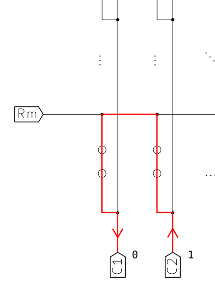
Push-pull problem
From the output, which is pulled to "1" (and does not hang in the Hi-Z state), current begins to flow. It passes through the nearest closed button, then through the closed button in the column being polled, and finally flows directly into the output set to “0”. This can lead to anything - from the inability to reliably read the state of the keyboard and ending with the failure of the microcontroller itself.
But since we are forced to somehow deal with this problem, we can apply an excellent trick: turn the push-pull exit into something like an open-drain outlet. I often came across this solution in the construction of old keyboards. Given that the current should only flow into the outputs (connected to the columns), but never flow out of them, we can limit the direction of the current with the help of diodes. A diode is a simple device that allows current to flow in only one direction. In the image of the diode on the electrical circuit, a triangle symbolizes an arrow that indicates this direction. If we put a diode between each output of the microcontroller and the conductor of the corresponding matrix column, then we will achieve our goal - now the current can only flow into the outputs, because the specified conductors reach each button of their column. It turns out that from the output set to "1", the current will not flow anywhere, and this almost turns it into an output with an open drain. Of course, it does not reach the current OS, but it solves our problem of a closed current loop in the keyboard matrix. Go back to the penultimate pattern of the matrix, but this time take into account the green diodes to understand how this trick works.
Naturally, it makes sense to minimize the number of diodes. To do this, you can reduce the number of columns by increasing the number of rows. And if the resulting result does not fit well into the actual keyboard layout, then you can "expand" the matrix by 90 ° (swap rows with columns). The possibilities are endless. But nowadays, a huge number of microcontrollers have appeared, which are easy to use and convenient for hobbyists, so today the described method is practically not used in homegrown keyboard projects. Luckily.
If you are interested in clavs, you must have already met this term. Unfortunately, in the keyboard world, it is often interpreted incorrectly.
We are already familiar with the situation when the simultaneous pressing of several buttons on one line can interfere with the normal reading of the matrix. And this problem, we can say, is solved by us. And now let's see what happens if you press several buttons that are simultaneously in one line and in one column.

Phantom push example
In the figure, the three buttons are pressed simultaneously. Two of them are in the “C2” column, and two in the “Rm” line. This means that one of the pressed buttons divides the line with the other pressed button, and the column with the third pressed button. It is in this situation that phantom depression occurs. Imagine that at the moment we are querying the “C1” column (that is, it is pushed to the ground - it is in the “0” state). Such a characteristic chord of the pressed buttons leads to the following: even though the left top button is not pressed, the string "R2" is in the state "0", because it is pressed to the ground by the column "C1" (located in "0") through three pushed buttons. As a result, the keyboard controller reads the left upper button as “pressed”, regardless of whether it is actually pressed or not. The described situation is called phantom pressing ( ghosting ), because some combinations of simultaneously pressed buttons cause phantom triggers of other buttons (ghost keypresses), although physically these other buttons are not pressed.
Of course, there are ways to protect compositors and gamers from phantom positives, and these methods are widely used in modern computer keyboards. You can catch the moment of occurrence of phantom depression and block it. An ordinary person is not able to simultaneously press or release two keys with perfect accuracy. Therefore, scanning the matrix quickly enough, we can assume that between two passes through the matrix, it can change no more than one button. In such a case, the controller accepts single presses and monitors the occurrence of situations in which two or more buttons are pressed between the matrix passes. Given that the matrix is scanned at a speed at which the regular occurrence of such situations is extremely unlikely, we can conclude that one of the buttons just pressed is a phantom. Therefore, the controller must ignore all of these presses. In addition, it is safer not to immediately inform the computer about changes in the status of the keyboard — first, it makes sense to wait until all these alarms disappear.
There is another approach. You can identify the situation when the “third” button is triggered, and block both this click and all subsequent ones. Do not remove the lock until the phantom operation disappears and the situation becomes normal again. To implement this approach, the program must remember exactly which buttons are pressed now (and usually it remembers this and so) in order to reject the subsequent actuation of the buttons, in the rows and columns of which the simultaneous presses are already fixed. If you write the program wisely, only problem triggering will be blocked, and all subsequent ones will be accepted as usual - except for those that again break the rules. Since the controller rejects pressing each button that already has simultaneous operation in its row and column, it turns out that, depending on the status of some buttons, others may not be registered at all. This situation is commonly known as jamming . That is, the buttons that prevent the simultaneous operation of other buttons, it turns out, "block" part of the keyboard.
From the user's point of view, you can simultaneously press all the buttons from one column (without pressing the buttons from the other), but you can simultaneously press all the buttons from one line only if each of these buttons has no more than one trigger in the column. The same applies to pressing buttons from one column - additional operations are recorded only if the buttons are in rows that are “not occupied”.
People often confuse “ phantom triggering ” and “ blocking triggering ” (“ ghosting ” and “ jamming ”), which is a mystery to me personally - in my opinion, these terms are quite intuitive.
In keyboards using such matrices, as we have just considered, it is impossible to avoid neither phantom operations, nor blocking.Since phantom triggers in everyday work are unacceptable, to combat them, almost all manufacturers of rubber dome keyboards use various tricks, and blocking comes into play. Question: how to create a matrix in such a way that blocking occurs as little as possible and would not be caused by common keyboard shortcuts? In fact, this is a good topic for a whole book; That is why the matrixes of shirpredetovsky keyboards are so intricate and always block a good mood (like, pun).
If you look at the image about phantom clicks again, you will be able to notice that the bottom right button is to blame for everything.
But this button is the only one through which the current flows in this situation “upward”. So, if we don’t want the current “up” currents to prevent us from reading the matrix normally, then let us introduce diodes so that the current can flow along the columns strictly from top to bottom, flowing into the microcontroller outputs.
Unfortunately, saving here will not work - you have to put a diode on each button. If we talk about polarity, then you should have figured out that in this particular case, the diodes must pass the current “top to bottom”, that is, their cathodes (“arrow tips”) should look at the microcontroller outputs (columns), while the anodes should be turned to the inputs (lines).

Summary Matrix
It does not matter which side of the button the diode is located; the main thing is to observe the correct polarity. Just remember that in this case the current will always flow from the inputs to the outputs. By the way, if the inputs are pulled to the power supply, and the outputs are in the OS mode, then this will always happen.
With this approach, it turns out that the current will always flow "right down", and this eliminates the appearance of closed current paths by simultaneously pressing several buttons. In addition, this design is the only one that can provide the keyboard with a full NKRO. In addition, it is useful to mention (although it seems obvious) that the problem of the absence of the OS mode from the microcontroller's outputs is now solved automatically. Diodes installed in series with each button, relieve the outputs from the circuit is not worse than the previously considered option, where it was supposed to additionally put a diode on each column.
Yes, I know that the text is already too long. But I still add this last chapter, because, in my opinion, without it the article will be incomplete. So, rollover is the ability of the keyboard to perceive several taps at the same time.
KRO is key rollover ( key a rollover ), and usually this abbreviation is entitled by some number. For example, 2KRO means two-key rollover. A keyboard has an x- keyboard rollover if and only if it is able to register x simultaneous key presses, moreover, regardless of which buttons and in what sequence were used. Most modern rubber dome keyboards have 2KRO. From this, however, it does not follow that the permissible number of clicks on these keyboards will always be limited to the number x . In fact, this means that support for x simultaneous clicks is guaranteed exactly.
Depending on the design of the matrix and the type of controller, two 2KRO keyboards from different manufacturers may behave quite differently. One can always perceive only two simultaneous presses, and the other can easily digest and more. It seems that the last keyboard was declared 2KRO because some key combinations (most likely, unlikely) will still cause her to block the pressing of other buttons. And since this means that when working with this keyboard, certain combinations of three keys and more will not work, the company announced it as 2KRO.
The term NKRO means N-key rollover , and is used to designate keyboards that support, in spite of everything, any combination of keys pressed at the same time. But keep in mind that the NKRO matrix and the NKRO keyboard are two big differences. For example, if the final implementation of the matrix, considered by us in the article, supports the NKRO (taking into account the correctly written firmware), then this does not mean that the keyboard using this matrix will also support the NKRO. This may be due to the limitations imposed by the communication ports to which the keyboard is connected; another reason may be the thrift of manufacturers, forever saving here and there. The problem of NKRO when connecting with PS / 2 and USB, I will try to clarify in the following sections.
Of course, the sheet came out pretty, but the concept is not so simple - especially for the reader who is not an electronic engineer. I hope I managed to explain everything; However, I tried to write as clearly as possible. Therefore, to some of you, the article might seem rather boring. Well, and if you are fumbling in electronics, then, most likely, you should not have read it at all;)
In any case, please let me know if the article turned out to be useful for you and whether it is worth writing a sequel. If yes, then sit down for the next "series".
Michał Trybus
September 2, 2013
Original : blog.komar.be/how-to-make-a-keyboard-the-matrix
This is the first post in the keyboard series; I hope he will not be the last. I would like to end up with a course on making a keyboard from scratch. Today I will talk about digital I / O and keyboard matrixes. Arm yourself with elementary school knowledge from the field of electronics - and let's go.
Why the matrix?
And how are we going to do the matrix? And most importantly - why is it even needed? Well, the matter is that, basically, the physical limitations of microcontrollers, on the basis of which keyboards are built. The fact is that with an increase in the number of outputs in microcontrollers and programmable logic chips, their size also grows, which, in turn, entails an increase in energy consumption and opportunities, but the main thing is prices. As a result, you can choose either a cheap chip with a small performance (which suits you perfectly), but with a small number of inputs and outputs, or a more powerful chip, whose performance, however, greatly exceeds your requirements. But only this powerful chip will have enough pins to connect every button on the keyboard.
Over the decades, the practice of electronics has been developed with the help of various tricks to artificially expand the embedded communication capabilities of processors and controllers. One of these methods, which is well suited for mechanical contacts (buttons), is the creation of a matrix. To understand how it works, some basic knowledge is required. Before we continue, please refresh Ohm’s law .
')
Some theory
To understand how digital electronics works, you need to learn two basic principles.
Principle one states that the process of communication within the scheme is not the transmission or receipt of something there. To ensure communication between the two devices, you simply interconnect their leads with an electrically conductive material. After that, it is assumed that the state of the material (voltage and current) at both its ends will be the same. In reality, this, of course, is not so, but for slow communications and short conductors, our assumption works perfectly. It turns out that sending and receiving information is in fact its sharing.
On the transmitter side, you simply change the electrical state of the conductor (by firing direct current into it, changing its potential), hoping that the receiver will be able to detect this change and understand it correctly.
It also follows from this principle that there is no dependence between the direction of communication and the direction of electric current. Many people mistakenly assume the opposite, and this prevents them from understanding how electronics work.
If you want to send a logic level "0", then usually the voltage at the output of the transmitter is lowered to 0 V, and a current begins to flow from the receiver to the transmitter so that the receiver can determine that the logic level corresponds to "0". (Whereas the reverse direction of the current would mean that somewhere in the circuit there is a negative potential - and this, as a rule, does not happen in digital electronics.) On the other hand, a voltage equal to the supply voltage is applied to transfer the logic level "1" and since this is, most often, the highest voltage in the circuit, there will be nothing left for the electric current to flow from the transmitter to the receiver.
Principle number two is that it is impossible to determine the state of the conductor without changing this state. It doesn't matter if you are going to measure voltage or current — in any case, it requires that electrons flow through your meter. The flow of electrons is the electric current, and once it flows, it means that in the node to which you connected for measurement, the currents and voltages have already changed (see Kirchhoff's laws ). From this it follows that if you need to “transfer” information by changing the state of the output electrically connected to another output, then this requires maintaining this state, and therefore, must comply with all requirements imposed by the receiver.
Button
A mechanical button (and in this context, the word “mechanical” is not associated with the phrase “mechanical keyboard”) is just a pair of metal contacts that, when touching, electrically connect the two terminals. Of course, there are other types of switches, structurally more complex and having more conclusions, but they are not interesting to us, because they are not used in keyboards.
Cherry MX button. Image source: Deskthority wiki
Well, and how will we connect the button to the input of the microcontroller? In principle, any input can operate with two possible logical levels: "0" and "1". It is common practice to accept voltages close to 0 V as a logical zero, and voltages close to the supply voltage (usually 5 V or 3.3 V) as a logical unit. But the problem is that the mechanical button cannot control the voltage itself. It controls the current - that is, if we connect two nodes with different electric potential through the button, then the current between these nodes will flow if and only when the button is pressed.
But if we add a resistor, we can very easily convert current into voltage.
Pull Resistor Button
Take a look at this diagram. When the button is not pressed (the circuit is broken), the current does not flow through it, so the voltage at node “A” will be close to the supply voltage VCC (in fact, less than VCC by the voltage drop across the resistor equal to R • I). When the button is pressed (the circuit is closed), the current flows through the resistor to ground. Taking into account that the resistance of the closed button is very small (about hundreds of millimets), the voltage at the node “A” will be close to “0”.
In this configuration, the resistor is called pull-up, because it "pulls the voltage up" to the level of VCC. And without connecting to the power through the resistor, there would be no voltage at the node “A” at all (in this case, the output of the microcircuit is called “hanging in the air” or in a high-impedance state).
It should be noted that inside most modern microcontrollers already have pull-up resistors that can be quickly connected or disconnected using the program. So, the main way to connect a button with a microcontroller is the following: one button output - to the input of the microcontroller, another button output - to the ground. In this case, if the button is not pressed, then the microcontroller is fed "1", and if it is pressed, then "0". Perhaps this is contrary to intuition, but this method of connection is the most popular.
Please note that if we leave one of the pins of the button hanging in the air, that is, we don’t connect it anywhere, then this button will not work at all: do not press it, it will not affect the electrical status of the microcontroller. We still use this property when we make the matrix.
Matrix principle
The basic principle of the keyboard matrix is the ability to connect to one input of the microcontroller more than one button.
With the help of transistors or properly configured outputs of the microcontroller, we can make the buttons connect to the earth one at a time, while the others will hang in the air. The remaining pins of each of the buttons are combined into one node and connected to the input of the microcontroller. I lowered the pull-up resistor, since we know that it is already present inside the microcontroller, in its input stage. We in turn “turn on” each button, connecting its pin number 1 to the ground via the corresponding output of the microcontroller, after which we can read the button state by removing the voltage from its pin number 2. Other buttons connected to the same input do not affect on his condition, because their conclusions number 1 are currently hanging in the air. The following diagram illustrates this idea.
Many buttons, one input (node "A")
“A” is the only input of the microcontroller, and “C1” .. “Cn” is its outputs. A logical "0" is set at one of the outputs, that is, inside the chip, this contact is somehow connected to ground - therefore, the current will always flow to this contact (in accordance with the first basic principle). Now, when the button connected to this output is pressed, through it the input “A” will immediately “press” to the ground, and it will be set to “0”. Pressing the other buttons will not change anything, because their earthen findings are not connected at any given time. When we need to poll the next button, we remove the logical “0” from the current output and set this level to the next output, so that at any time only one of the microcontroller outputs will be activated.
Such a configuration (when the output is either connected to ground or disconnected altogether) is called an open drain outlet (OS) (historically, an open collector (OK)). Here I made some simplification - in fact, the contact cannot be completely disconnected from the circuit, unless it is physically cut off from it. But for simple digital I / O, such a simplification is fine. Most microcontrollers provide the ability to programmatically configure their output pins for operating in OS mode. But what if we do not have such an opportunity? There is another configuration - push-pull mode; Today this option is one of the most popular. This configuration works a little differently. In the “0” state, the output is still pressed down to the ground, but when the “1” state comes, it is pulled up to the VCC supply voltage, so that the air outlet no longer hangs, now it can become a current source.
What changes will this entail in the design of the matrix? If we are not going to press several buttons at the same time, then none. But if we are going to, look at the picture and imagine for a second what will happen then. By pressing two buttons, we connect the two lower outputs into a closed loop. If at the same time one of them is in the “0” state and the other is in the “1” state, then an electrical current will flow from the output set to “1” to the output set to “0”. And since this current is not limited by anything (no resistors), not only does the circuit become unstable, the chip can fly as well. Well and, by itself, hardly it will turn out to consider a logical state normally.
Adding lines
You can consider the previous example as a matrix consisting of one row. Now let's increase it by adding extra lines. In fact, if we can hang a whole line on one input, then why can't we hang a whole column of buttons on one output? True, there is a prerequisite - each button of the column must be connected to a separate input of the microcontroller.
If we arrange the buttons in the form of an ordinary matrix, then this condition will be fulfilled automatically. And the following figure shows how the matrix of buttons will look like, consisting of n columns and m rows ( do not pay attention to the green figures yet ).
Simple keyboard matrix
Reading this matrix is very simple. We poll one column at a time. The column for reading is selected by connecting one of the outputs "C1" .. "Cn" to the ground (the output in the OS mode is converted to "0"). Now, alternately polling the lines "R1" .. "Rm", we can determine the state of each button of the selected column. Buttons from other columns do not affect anything, even if they are pressed, because at the moment their ground leads are hanging in the air (or, as they say in electronics, they are in the Hi-Z state).
After the entire column is polled, we proceed to the next one, releasing the current output and pressing the next one to zero. Matrix scanning is considered complete when all columns are polled. If everything is done fairly quickly, then the fastest typesetter will not notice the intervals between polling columns. Even with a 16 MHz microcontroller, we can easily scan the entire matrix thousands of times per second, while the fastest typesetter in the hi-games.net test achieved a speed of 203 words per minute (wpm) - that is, a little less than 17 taps in give me a sec.
When designing a keyboard using a matrix, we reduce the number of pins required to connect all the keys. But in order to reduce the number of conclusions to the minimum possible, we need to make a matrix so that the number of columns is as close as possible to the number of rows. In an ideal situation, if the number of buttons is n² , then the best that we can achieve with a matrix is 2n busy microcontroller pins. However, today when compiling matrices, it is rare that anyone seeks to minimize the number of legs involved, because modern microcontrollers, as a rule, have a sufficient number of free outputs. In addition, the maximum optimization of the matrix can later lead to inconveniences — the wiring of the board or the distribution of wires in the end device will become significantly more complicated. Therefore, it is worth going a more convenient way: in drawing up the matrix, try to follow the physical arrangement of the buttons. In this case, for a standard computer keyboard, the simplest matrix will have only 6 rows and a certain number of columns, depending on the desired layout. Of course, from the point of view of the number of conclusions involved, this solution is not the most optimal, but in the future, at least, the wiring will be simplified.
But what if we don’t have open drain exits?
You may ask: what can we do if there is no OS mode in the selected microcontroller? Well, we have already figured out what kind of trouble can happen, and that pulling the outputs to the VCC (that is, “connecting” them with power) is not a good idea. There are many ways to solve this problem; Among them there are not only special output buffers of the OS, but even shift registers with OS-outputs - to further minimize the number of legs involved. But there is another very popular technique that is often used in the construction of computer keyboards (in fact, it was widely used in the old days).
The problem of the columns connected to the push-pull outputs is manifested at the moment when two buttons are pressed together that are in the same line, and at the same time pressing this button a poll is performed in which one of the buttons is located.
Push-pull problem
From the output, which is pulled to "1" (and does not hang in the Hi-Z state), current begins to flow. It passes through the nearest closed button, then through the closed button in the column being polled, and finally flows directly into the output set to “0”. This can lead to anything - from the inability to reliably read the state of the keyboard and ending with the failure of the microcontroller itself.
But since we are forced to somehow deal with this problem, we can apply an excellent trick: turn the push-pull exit into something like an open-drain outlet. I often came across this solution in the construction of old keyboards. Given that the current should only flow into the outputs (connected to the columns), but never flow out of them, we can limit the direction of the current with the help of diodes. A diode is a simple device that allows current to flow in only one direction. In the image of the diode on the electrical circuit, a triangle symbolizes an arrow that indicates this direction. If we put a diode between each output of the microcontroller and the conductor of the corresponding matrix column, then we will achieve our goal - now the current can only flow into the outputs, because the specified conductors reach each button of their column. It turns out that from the output set to "1", the current will not flow anywhere, and this almost turns it into an output with an open drain. Of course, it does not reach the current OS, but it solves our problem of a closed current loop in the keyboard matrix. Go back to the penultimate pattern of the matrix, but this time take into account the green diodes to understand how this trick works.
Naturally, it makes sense to minimize the number of diodes. To do this, you can reduce the number of columns by increasing the number of rows. And if the resulting result does not fit well into the actual keyboard layout, then you can "expand" the matrix by 90 ° (swap rows with columns). The possibilities are endless. But nowadays, a huge number of microcontrollers have appeared, which are easy to use and convenient for hobbyists, so today the described method is practically not used in homegrown keyboard projects. Luckily.
Phantom clicks (Ghosting)
If you are interested in clavs, you must have already met this term. Unfortunately, in the keyboard world, it is often interpreted incorrectly.
We are already familiar with the situation when the simultaneous pressing of several buttons on one line can interfere with the normal reading of the matrix. And this problem, we can say, is solved by us. And now let's see what happens if you press several buttons that are simultaneously in one line and in one column.
Phantom push example
In the figure, the three buttons are pressed simultaneously. Two of them are in the “C2” column, and two in the “Rm” line. This means that one of the pressed buttons divides the line with the other pressed button, and the column with the third pressed button. It is in this situation that phantom depression occurs. Imagine that at the moment we are querying the “C1” column (that is, it is pushed to the ground - it is in the “0” state). Such a characteristic chord of the pressed buttons leads to the following: even though the left top button is not pressed, the string "R2" is in the state "0", because it is pressed to the ground by the column "C1" (located in "0") through three pushed buttons. As a result, the keyboard controller reads the left upper button as “pressed”, regardless of whether it is actually pressed or not. The described situation is called phantom pressing ( ghosting ), because some combinations of simultaneously pressed buttons cause phantom triggers of other buttons (ghost keypresses), although physically these other buttons are not pressed.
Of course, there are ways to protect compositors and gamers from phantom positives, and these methods are widely used in modern computer keyboards. You can catch the moment of occurrence of phantom depression and block it. An ordinary person is not able to simultaneously press or release two keys with perfect accuracy. Therefore, scanning the matrix quickly enough, we can assume that between two passes through the matrix, it can change no more than one button. In such a case, the controller accepts single presses and monitors the occurrence of situations in which two or more buttons are pressed between the matrix passes. Given that the matrix is scanned at a speed at which the regular occurrence of such situations is extremely unlikely, we can conclude that one of the buttons just pressed is a phantom. Therefore, the controller must ignore all of these presses. In addition, it is safer not to immediately inform the computer about changes in the status of the keyboard — first, it makes sense to wait until all these alarms disappear.
There is another approach. You can identify the situation when the “third” button is triggered, and block both this click and all subsequent ones. Do not remove the lock until the phantom operation disappears and the situation becomes normal again. To implement this approach, the program must remember exactly which buttons are pressed now (and usually it remembers this and so) in order to reject the subsequent actuation of the buttons, in the rows and columns of which the simultaneous presses are already fixed. If you write the program wisely, only problem triggering will be blocked, and all subsequent ones will be accepted as usual - except for those that again break the rules. Since the controller rejects pressing each button that already has simultaneous operation in its row and column, it turns out that, depending on the status of some buttons, others may not be registered at all. This situation is commonly known as jamming . That is, the buttons that prevent the simultaneous operation of other buttons, it turns out, "block" part of the keyboard.
From the user's point of view, you can simultaneously press all the buttons from one column (without pressing the buttons from the other), but you can simultaneously press all the buttons from one line only if each of these buttons has no more than one trigger in the column. The same applies to pressing buttons from one column - additional operations are recorded only if the buttons are in rows that are “not occupied”.
People often confuse “ phantom triggering ” and “ blocking triggering ” (“ ghosting ” and “ jamming ”), which is a mystery to me personally - in my opinion, these terms are quite intuitive.
In keyboards using such matrices, as we have just considered, it is impossible to avoid neither phantom operations, nor blocking.Since phantom triggers in everyday work are unacceptable, to combat them, almost all manufacturers of rubber dome keyboards use various tricks, and blocking comes into play. Question: how to create a matrix in such a way that blocking occurs as little as possible and would not be caused by common keyboard shortcuts? In fact, this is a good topic for a whole book; That is why the matrixes of shirpredetovsky keyboards are so intricate and always block a good mood (like, pun).
Diodes on all buttons - the cardinal solution
If you look at the image about phantom clicks again, you will be able to notice that the bottom right button is to blame for everything.
But this button is the only one through which the current flows in this situation “upward”. So, if we don’t want the current “up” currents to prevent us from reading the matrix normally, then let us introduce diodes so that the current can flow along the columns strictly from top to bottom, flowing into the microcontroller outputs.
Unfortunately, saving here will not work - you have to put a diode on each button. If we talk about polarity, then you should have figured out that in this particular case, the diodes must pass the current “top to bottom”, that is, their cathodes (“arrow tips”) should look at the microcontroller outputs (columns), while the anodes should be turned to the inputs (lines).
Summary Matrix
It does not matter which side of the button the diode is located; the main thing is to observe the correct polarity. Just remember that in this case the current will always flow from the inputs to the outputs. By the way, if the inputs are pulled to the power supply, and the outputs are in the OS mode, then this will always happen.
With this approach, it turns out that the current will always flow "right down", and this eliminates the appearance of closed current paths by simultaneously pressing several buttons. In addition, this design is the only one that can provide the keyboard with a full NKRO. In addition, it is useful to mention (although it seems obvious) that the problem of the absence of the OS mode from the microcontroller's outputs is now solved automatically. Diodes installed in series with each button, relieve the outputs from the circuit is not worse than the previously considered option, where it was supposed to additionally put a diode on each column.
Rollover
Yes, I know that the text is already too long. But I still add this last chapter, because, in my opinion, without it the article will be incomplete. So, rollover is the ability of the keyboard to perceive several taps at the same time.
xKRO
KRO is key rollover ( key a rollover ), and usually this abbreviation is entitled by some number. For example, 2KRO means two-key rollover. A keyboard has an x- keyboard rollover if and only if it is able to register x simultaneous key presses, moreover, regardless of which buttons and in what sequence were used. Most modern rubber dome keyboards have 2KRO. From this, however, it does not follow that the permissible number of clicks on these keyboards will always be limited to the number x . In fact, this means that support for x simultaneous clicks is guaranteed exactly.
Depending on the design of the matrix and the type of controller, two 2KRO keyboards from different manufacturers may behave quite differently. One can always perceive only two simultaneous presses, and the other can easily digest and more. It seems that the last keyboard was declared 2KRO because some key combinations (most likely, unlikely) will still cause her to block the pressing of other buttons. And since this means that when working with this keyboard, certain combinations of three keys and more will not work, the company announced it as 2KRO.
NKRO
The term NKRO means N-key rollover , and is used to designate keyboards that support, in spite of everything, any combination of keys pressed at the same time. But keep in mind that the NKRO matrix and the NKRO keyboard are two big differences. For example, if the final implementation of the matrix, considered by us in the article, supports the NKRO (taking into account the correctly written firmware), then this does not mean that the keyboard using this matrix will also support the NKRO. This may be due to the limitations imposed by the communication ports to which the keyboard is connected; another reason may be the thrift of manufacturers, forever saving here and there. The problem of NKRO when connecting with PS / 2 and USB, I will try to clarify in the following sections.
Total
Of course, the sheet came out pretty, but the concept is not so simple - especially for the reader who is not an electronic engineer. I hope I managed to explain everything; However, I tried to write as clearly as possible. Therefore, to some of you, the article might seem rather boring. Well, and if you are fumbling in electronics, then, most likely, you should not have read it at all;)
In any case, please let me know if the article turned out to be useful for you and whether it is worth writing a sequel. If yes, then sit down for the next "series".
Michał Trybus
September 2, 2013
Source: https://habr.com/ru/post/394585/
All Articles