Making a three-axis milling machine with numerical control
The idea to make a machine at home with your hands is not new. Everyone who thinks about the implementation of such equipment in the home, should be guided by their motive of creation. It is necessary for me, because by nature I do not have so many even hands to make good, even more or less dimensional, parts, and often there is a task to make an exact complicated part, with which the machine will cope well. There are always enough new ideas and ideas for implementation, and there is not much time.

The resulting milling machine must meet the following conditions:
The main rule of machines - rigidity. The higher the rigidity of the machine, the less vibrations, backlashes, sagging, bending and other defects that affect the quality of the processed blank. Since the machine will be made completely at home, the only material that can actually be processed in such a quantity at home and from which it will turn out to make the machine bed is wood. There are of course different types. And in the absence of large capitalfor the student to create will be used everything that exists. And this is essentially a plank on test with a drill of a rather soft wood. Although there are also small sheets of plywood. Than rich, it will be used.
')
It is also worth noting on what will run the machine control. There is one very ancient computer, its shore is just about for such purposes. AMD Duron 1.2 GHz, RAM 768 MB, 64 MB Video Mem, HDD 20GB. Just for these purposes will fit. Management will be under Linux CNC. For Mach3 under Win did not want to work intelligently. He needs a little more resources.
The development of the machine will be divided into several parts.
It should immediately be said that the development of the mechanical part as such was absent, for there is not so much experience to develop and foresee something. On this development was carried out immediately at the assembly stage.
A stepper motor controller will be designed on a PIC microcontroller. Why? Firstly, it was necessary to finally understand how stepper motors work, secondly, it is more interesting, thirdly, the L297 ready-made microcircuit was worth a little expensive for some reason, and in the end it turned out to be a little cheaper to assemble on a microcontroller.

PIC16F630 was taken as the control microcontroller. It has a minimum of peripherals and enough legs to control. Port C serves for direct output of control pulses. The pins A1, A2 are input signals DIR, STEP. Pin A2 is enabled in external interrupt mode, and DIR works as a normal input pin. The controller is launched through quartz at 20 MHz.
The code was written in C using a small asm insert and compiled on a CCS C compiler.
To describe the code, it will be easier to start with the logic of the controller. When the controller starts, the initial setup of the hardware and the activation of interrupts occur. The step number is stored in the unsigned 8-bit variable nowStep and at the beginning the number is zero. Next, the program runs an eternal loop in MAIN_LOOP in which it just blinks the LED connected to pin A0. For what? First, it is clear that the stone does not hang, and secondly, special effects! Pin A2 is configured for an external upstream interrupt. When an event is registered on a leg, an INT_EXT interrupt will be processed in which the next step is switched. To output the next step, the nowStep step pointer is incremented or decremented depending on the input DIR. Then, from the array of steps steps from the nowStep position, the new combination of motor winding switching is output to the port. Also, at the beginning of the initialization of the microcontroller, the timer 1 is set and started. This timer resets the output signals to prevent the engines from overheating. The timer resets the output signals after about 100 ms after setting the signal. That is, this is purely a precaution.
In the simulation, the CLK signal period of 15 µs was reached, which corresponds to a frequency of 66. (6) KHz. For the first time is not bad, I think, though, further optimization is possible.
There is no need to go far. Typical scheme. The driver is based on the ready-made driver L298N.

Why resistors R1 - R4? Honestly, I do not know. Initially, the documentation is a diagram in conjunction with L297, the entire connection without resistors. However, the Internet found a circuit with resistors on the lines. I looked at the block diagram in the datasheet on the L298N. All INPUT lines enter the inverse AND of the element. Nothing should happen without resistors. But I decided not to risk and just in case insert it, this time. It will not be much worse, the steepness of the front at the entrance will fall.
The rest of the scheme repeats the one that is given in the datasheet.
The optocoupler circuit serves to protect the control machine, in this case the computer, from the power section of the machine. So, if something starts to smoke from the machine, it only dodizes the opto-decoupling circuit and minimizes the damage.
The scheme is quite dimensional, so click to see the full size.
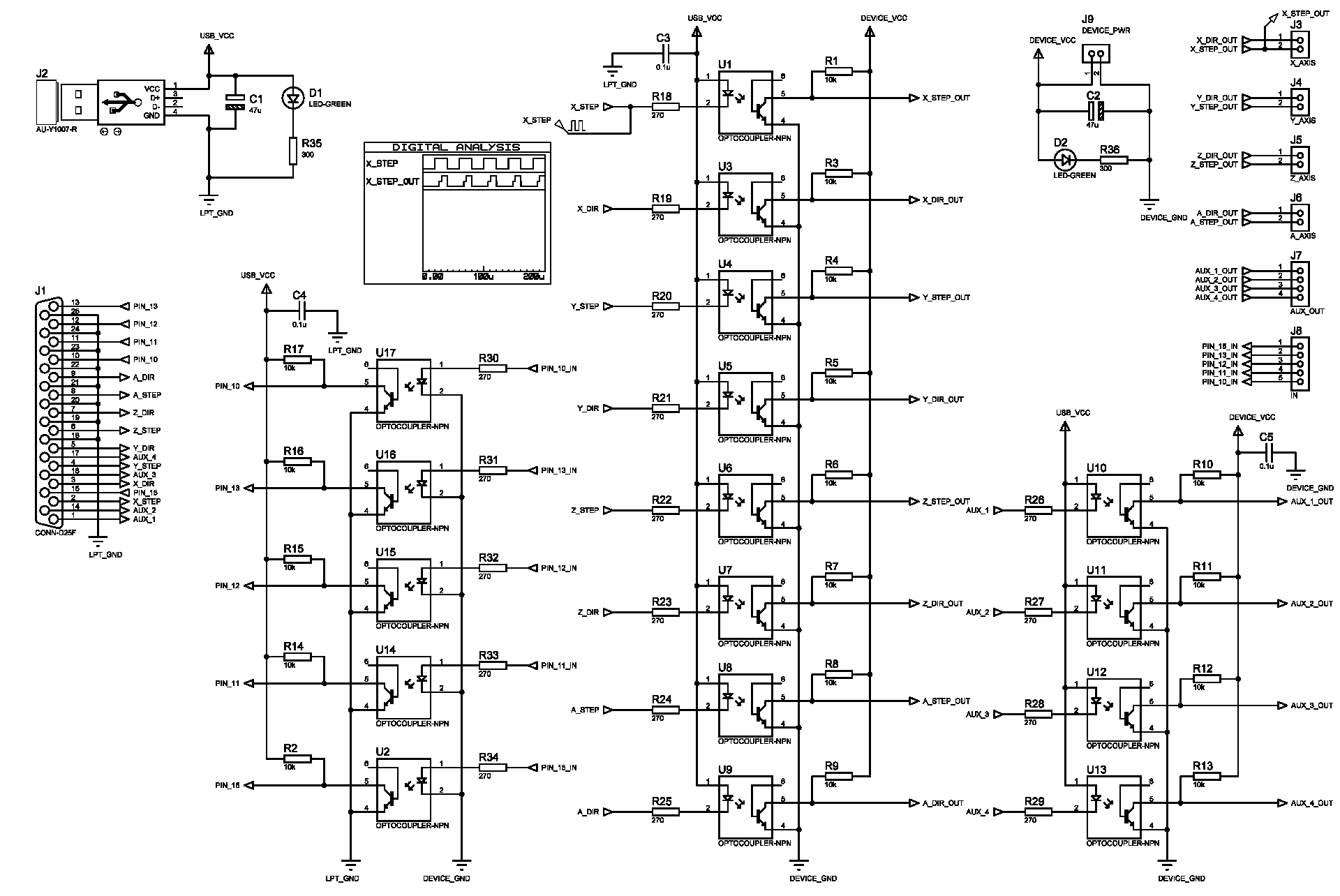
Optocouplers 4N25 were initially taken. For I thought that 60 kHz will pull out any of today's optocouplers. But in reality, no, they did not stretch, did not have time. Therefore, as a result, it was necessary to replace it with 6N135, whose performance is much higher (up to 2MHz in datasheet). On the pins, they are not directly compatible, however, we managed to insert them without reworking the entire board. I did not make a new scheme, I think, whoever wants it, he will be able to remap the board on his own.
As it should be, the power supply of the circuit is divided into two parts, from the side of the machine and from the side of the computer. From the side of the computer, power is supplied via a USB cable, this is its only purpose. On the machine side, any bundle of wires is already 5 V.
Also, since everything was done not by a monolith, but by small blocks, it was necessary to dissipate more wires than usual for power and for signals. Therefore, to simplify wiring, I decided to make a separate small bar with connectors for power wiring along the 12 V and 5 V lines.

The power strip contains six connectors for 5 V and 12 V lines, as well as two separate connectors for connecting coolers.
Since I didn’t begin to photograph from the very beginning, and I didn’t plan to write this article, many assembly steps are missing, but I’ll show those that are there. All photos in this section are clickable.
Transferred drawing LUTOM:
I etched and condemned:

Drilled:
Soldered:
Further, it was necessary to repeat the success for another 2 axes:
Moved with LUT and corrected with a marker:
Etched:


Buzz:
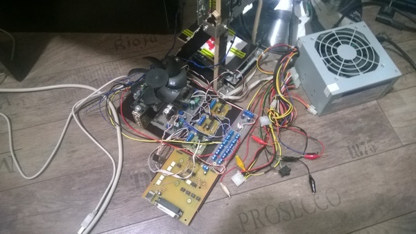
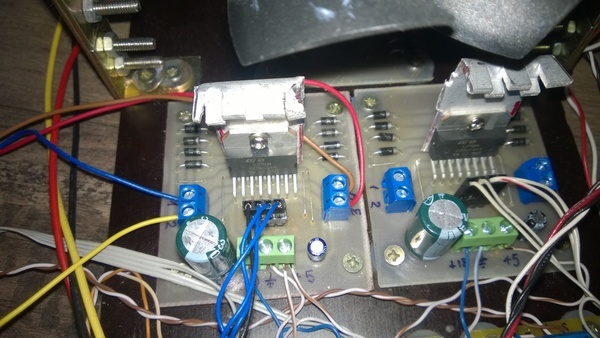
Assembled all electronics:

The machine was assembled from plywood 10 mm thick and 18 mm planks. When assembling furniture guides were used, it was better not to find anything for the first time, and psychologically I was not ready to process at least the same metal corners.
At first there was such a construction:
The first version of the Z axis:

But as I understand it now, it was no good at all, everything drove, staggered. In general, about any rigidity and speech was not.
There was another attempt:

During which the X and Y axes were moved to a separate platform and turned into a movable table:

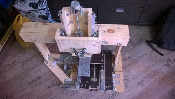
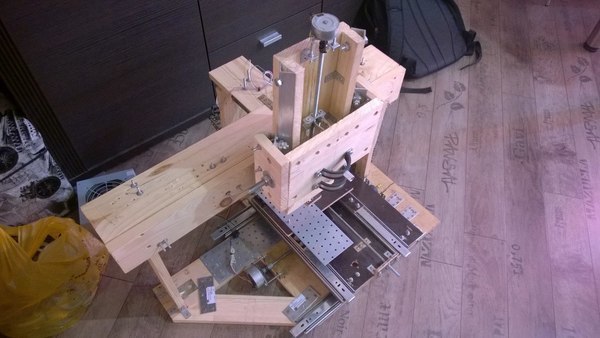
It was already better, but still very far from something that was not loose. As a result, came to this option:
However, the Z axis is still twitching and bending too much. This time I sat down and thought well and had already taken up some design. The result was this design:

Equal-shelf aluminum corners with a shelf of 25 mm and a thickness of 2 mm were used as guides. Steel could not find. They would be many times better. Guides of industrial production, of course, still do not go to any comparison.
Moving carriage:


Assembled new Z axis:

Result. You can see that the assembled axis, and the design as a whole, is still different even from the designed one. Nevertheless, to combine and center the axis when you only have a vernier caliper and a hand drill from a precise tool is not an easy task. For this, I had to rethink and experiment on the go:
Trying to milling something:
Even with so many if, even with such an imperfect construction, it turned out to create something working and the result I was impressed.
The control software of CNC machines must operate on real-time systems in order to generate accurately synchronized signals. Therefore, Windows is not very good for this. Of course, for the correct operation, drivers are written that solve this problem, but it usually requires more resources and the stability of such a system is lower than real-time systems.
Processing was done under LinuxCNC. Installation and configuration should not cause great difficulties. On the program site there are already ready builds and source codes for gourmets. There are several ways to install: on an already installed system or from scratch with a configured OS. I chose the second option, since I am not so experienced in working with Linux, and there was not enough time to deal with the patching process. The second option is the usual Debian distribution with the RTC kernel and the LinuxCNC already installed.
After installation, it is necessary to adjust the axes of the machines: signal mapping, movement speed, acceleration values, and so on. The result is an output file to run, which, when started, will show the machine control program itself with the specified parameters.
As a result of the work done, there are still a lot of impressions left, as well as questions and tasks for improving the resulting machine.
The resulting machine has a working area greater than 270 mm in the X and Y axes, and about 150 mm in Z. The speeds of movement along the X and Y axes are more than 500 mm / s, and in Z and 300 mm / s. It is at 12 V operating voltage. That is half of their performance. There is room to grow.
What can be said with certainty - it was worth it. At least one task the machine will do well now: cutting boards. You can forget about etching and LUT. Cutting boards has, of course, its drawbacks, but it is better to have alternatives than the only option. The video of the work showed how the 3 mm mill machine milled the letter M, maybe with a low feed rate and layers of 0.1 mm, but this is also the result.
I don’t see much point in spreading any sources or PCB boards. The machine did not turn out suitable for any serious loads or rather stable and unique. However, this is not the last attempt to do anything and the next iteration of development is being prepared, I hope, a better one.
Briefly about the author
Student of the 4th course of the Belarusian State University of Informatics and Radioelectronics, Faculty of "Computer Systems and Networks", Department of "Electronic Computers", specialty "Computers and Systems and Networks".
Student of the 4th course of the Belarusian State University of Informatics and Radioelectronics, Faculty of "Computer Systems and Networks", Department of "Electronic Computers", specialty "Computers and Systems and Networks".
Spoiler
The result obtained does not claim to be the machine of the year. Yes, the implementation of the SD controller on the microcontroller is not a very good option. Yes, the frame of wood, is also not the best thing you can think of. The text of the article will explain and justify the election. Do not forget that this is just an attempt to collect something, to gain experience and move on.
The result obtained does not claim to be the machine of the year. Yes, the implementation of the SD controller on the microcontroller is not a very good option. Yes, the frame of wood, is also not the best thing you can think of. The text of the article will explain and justify the election. Do not forget that this is just an attempt to collect something, to gain experience and move on.
Technical assignment or what to expect at the exit
The resulting milling machine must meet the following conditions:
- Have an acceptable workspace
- Have an acceptable speed of movement along the axes
- Handle wood parts of medium and high hardness. Ideally handle aluminum
The main rule of machines - rigidity. The higher the rigidity of the machine, the less vibrations, backlashes, sagging, bending and other defects that affect the quality of the processed blank. Since the machine will be made completely at home, the only material that can actually be processed in such a quantity at home and from which it will turn out to make the machine bed is wood. There are of course different types. And in the absence of large capital
')
It is also worth noting on what will run the machine control. There is one very ancient computer, its shore is just about for such purposes. AMD Duron 1.2 GHz, RAM 768 MB, 64 MB Video Mem, HDD 20GB. Just for these purposes will fit. Management will be under Linux CNC. For Mach3 under Win did not want to work intelligently. He needs a little more resources.
Development
The development of the machine will be divided into several parts.
- Development of a stepper motor controller
- Development of a stepper motor driver
- Optical Link Development
- Power plan development
It should immediately be said that the development of the mechanical part as such was absent, for there is not so much experience to develop and foresee something. On this development was carried out immediately at the assembly stage.
Development of a stepper motor controller
A stepper motor controller will be designed on a PIC microcontroller. Why? Firstly, it was necessary to finally understand how stepper motors work, secondly, it is more interesting, thirdly, the L297 ready-made microcircuit was worth a little expensive for some reason, and in the end it turned out to be a little cheaper to assemble on a microcontroller.
PIC16F630 was taken as the control microcontroller. It has a minimum of peripherals and enough legs to control. Port C serves for direct output of control pulses. The pins A1, A2 are input signals DIR, STEP. Pin A2 is enabled in external interrupt mode, and DIR works as a normal input pin. The controller is launched through quartz at 20 MHz.
The code was written in C using a small asm insert and compiled on a CCS C compiler.
#include <16f630.h> #case #FUSES NOWDT #FUSES NOMCLR #FUSES HS #FUSES PUT #FUSES BROWNOUT #use delay(clock = 20 MHz) #use fast_io(C) #opt 9 #define DIR PIN_A1 #define CLK PIN_A2 #define LED PIN_A0 #zero_ram //half step array const int steps[256] = { 0b00000100,0b00000110,0b00000010,0b00001010,0b00001000,0b00001001,0b00000001,0b00000101, 0b00000100,0b00000110,0b00000010,0b00001010,0b00001000,0b00001001,0b00000001,0b00000101, 0b00000100,0b00000110,0b00000010,0b00001010,0b00001000,0b00001001,0b00000001,0b00000101, 0b00000100,0b00000110,0b00000010,0b00001010,0b00001000,0b00001001,0b00000001,0b00000101, 0b00000100,0b00000110,0b00000010,0b00001010,0b00001000,0b00001001,0b00000001,0b00000101, 0b00000100,0b00000110,0b00000010,0b00001010,0b00001000,0b00001001,0b00000001,0b00000101, 0b00000100,0b00000110,0b00000010,0b00001010,0b00001000,0b00001001,0b00000001,0b00000101, 0b00000100,0b00000110,0b00000010,0b00001010,0b00001000,0b00001001,0b00000001,0b00000101, 0b00000100,0b00000110,0b00000010,0b00001010,0b00001000,0b00001001,0b00000001,0b00000101, 0b00000100,0b00000110,0b00000010,0b00001010,0b00001000,0b00001001,0b00000001,0b00000101, 0b00000100,0b00000110,0b00000010,0b00001010,0b00001000,0b00001001,0b00000001,0b00000101, 0b00000100,0b00000110,0b00000010,0b00001010,0b00001000,0b00001001,0b00000001,0b00000101, 0b00000100,0b00000110,0b00000010,0b00001010,0b00001000,0b00001001,0b00000001,0b00000101, 0b00000100,0b00000110,0b00000010,0b00001010,0b00001000,0b00001001,0b00000001,0b00000101, 0b00000100,0b00000110,0b00000010,0b00001010,0b00001000,0b00001001,0b00000001,0b00000101, 0b00000100,0b00000110,0b00000010,0b00001010,0b00001000,0b00001001,0b00000001,0b00000101, 0b00000100,0b00000110,0b00000010,0b00001010,0b00001000,0b00001001,0b00000001,0b00000101, 0b00000100,0b00000110,0b00000010,0b00001010,0b00001000,0b00001001,0b00000001,0b00000101, 0b00000100,0b00000110,0b00000010,0b00001010,0b00001000,0b00001001,0b00000001,0b00000101, 0b00000100,0b00000110,0b00000010,0b00001010,0b00001000,0b00001001,0b00000001,0b00000101, 0b00000100,0b00000110,0b00000010,0b00001010,0b00001000,0b00001001,0b00000001,0b00000101, 0b00000100,0b00000110,0b00000010,0b00001010,0b00001000,0b00001001,0b00000001,0b00000101, 0b00000100,0b00000110,0b00000010,0b00001010,0b00001000,0b00001001,0b00000001,0b00000101, 0b00000100,0b00000110,0b00000010,0b00001010,0b00001000,0b00001001,0b00000001,0b00000101, 0b00000100,0b00000110,0b00000010,0b00001010,0b00001000,0b00001001,0b00000001,0b00000101, 0b00000100,0b00000110,0b00000010,0b00001010,0b00001000,0b00001001,0b00000001,0b00000101, 0b00000100,0b00000110,0b00000010,0b00001010,0b00001000,0b00001001,0b00000001,0b00000101, 0b00000100,0b00000110,0b00000010,0b00001010,0b00001000,0b00001001,0b00000001,0b00000101, 0b00000100,0b00000110,0b00000010,0b00001010,0b00001000,0b00001001,0b00000001,0b00000101, 0b00000100,0b00000110,0b00000010,0b00001010,0b00001000,0b00001001,0b00000001,0b00000101, 0b00000100,0b00000110,0b00000010,0b00001010,0b00001000,0b00001001,0b00000001,0b00000101, 0b00000100,0b00000110,0b00000010,0b00001010,0b00001000,0b00001001,0b00000001,0b00000101 }; unsigned int8 nowStep = 0; #INT_TIMER1 void LoadDrop_isr() { output_c(0); } #INT_EXT void clk_isr() { //input_state(DIR) ? nowStep++ : nowStep--; #asm asis BTFSC 05.1 INCF nowStep,F BTFSS 05.1 DECF nowStep,F #endasm output_c(steps[nowStep]); set_timer1(0); } void main() { output_a(0); input_a(); set_tris_c(0); output_c(0); setup_comparator(NC_NC_NC_NC); setup_timer_1(T1_INTERNAL | T1_DIV_BY_8); set_timer1(0); ext_int_edge(L_TO_H); enable_interrupts(INT_TIMER1); enable_interrupts(INT_EXT); enable_interrupts(GLOBAL); unsigned int16 blinkCounter = 0; MAIN_LOOP: if(!blinkCounter++) output_toggle(LED); goto MAIN_LOOP; } To describe the code, it will be easier to start with the logic of the controller. When the controller starts, the initial setup of the hardware and the activation of interrupts occur. The step number is stored in the unsigned 8-bit variable nowStep and at the beginning the number is zero. Next, the program runs an eternal loop in MAIN_LOOP in which it just blinks the LED connected to pin A0. For what? First, it is clear that the stone does not hang, and secondly, special effects! Pin A2 is configured for an external upstream interrupt. When an event is registered on a leg, an INT_EXT interrupt will be processed in which the next step is switched. To output the next step, the nowStep step pointer is incremented or decremented depending on the input DIR. Then, from the array of steps steps from the nowStep position, the new combination of motor winding switching is output to the port. Also, at the beginning of the initialization of the microcontroller, the timer 1 is set and started. This timer resets the output signals to prevent the engines from overheating. The timer resets the output signals after about 100 ms after setting the signal. That is, this is purely a precaution.
In the simulation, the CLK signal period of 15 µs was reached, which corresponds to a frequency of 66. (6) KHz. For the first time is not bad, I think, though, further optimization is possible.
Development of a stepper motor driver
There is no need to go far. Typical scheme. The driver is based on the ready-made driver L298N.
Why resistors R1 - R4? Honestly, I do not know. Initially, the documentation is a diagram in conjunction with L297, the entire connection without resistors. However, the Internet found a circuit with resistors on the lines. I looked at the block diagram in the datasheet on the L298N. All INPUT lines enter the inverse AND of the element. Nothing should happen without resistors. But I decided not to risk and just in case insert it, this time. It will not be much worse, the steepness of the front at the entrance will fall.
The rest of the scheme repeats the one that is given in the datasheet.
Optical Link Development
The optocoupler circuit serves to protect the control machine, in this case the computer, from the power section of the machine. So, if something starts to smoke from the machine, it only dodizes the opto-decoupling circuit and minimizes the damage.
The scheme is quite dimensional, so click to see the full size.
Optocouplers 4N25 were initially taken. For I thought that 60 kHz will pull out any of today's optocouplers. But in reality, no, they did not stretch, did not have time. Therefore, as a result, it was necessary to replace it with 6N135, whose performance is much higher (up to 2MHz in datasheet). On the pins, they are not directly compatible, however, we managed to insert them without reworking the entire board. I did not make a new scheme, I think, whoever wants it, he will be able to remap the board on his own.
As it should be, the power supply of the circuit is divided into two parts, from the side of the machine and from the side of the computer. From the side of the computer, power is supplied via a USB cable, this is its only purpose. On the machine side, any bundle of wires is already 5 V.
Power plan development
Also, since everything was done not by a monolith, but by small blocks, it was necessary to dissipate more wires than usual for power and for signals. Therefore, to simplify wiring, I decided to make a separate small bar with connectors for power wiring along the 12 V and 5 V lines.
The power strip contains six connectors for 5 V and 12 V lines, as well as two separate connectors for connecting coolers.
Assembly and result
Since I didn’t begin to photograph from the very beginning, and I didn’t plan to write this article, many assembly steps are missing, but I’ll show those that are there. All photos in this section are clickable.
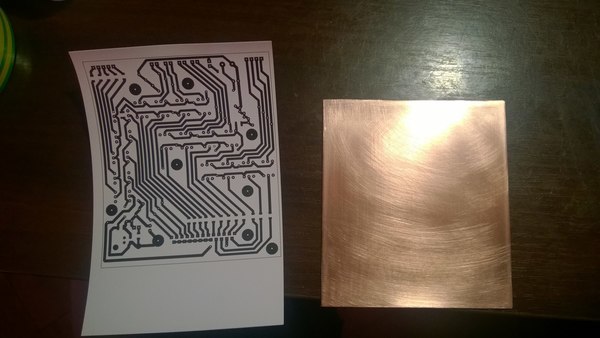
Manufacturing driver stepper motor
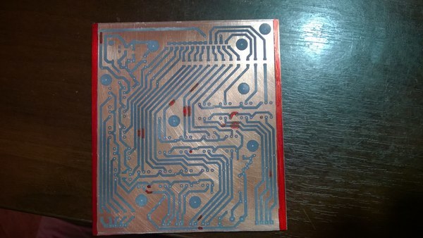
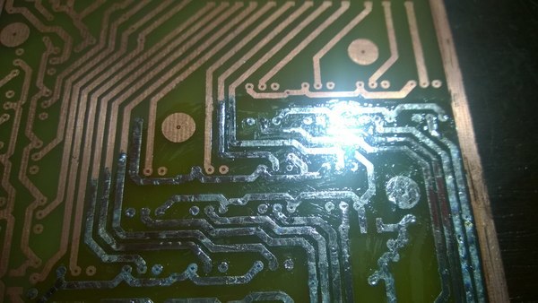
Transferred drawing LUTOM:
I etched and condemned:
Drilled:
Soldered:
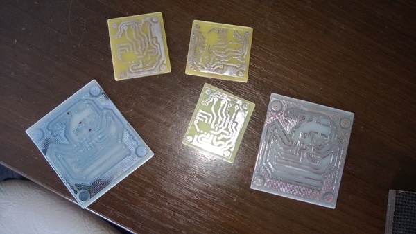
Further, it was necessary to repeat the success for another 2 axes:
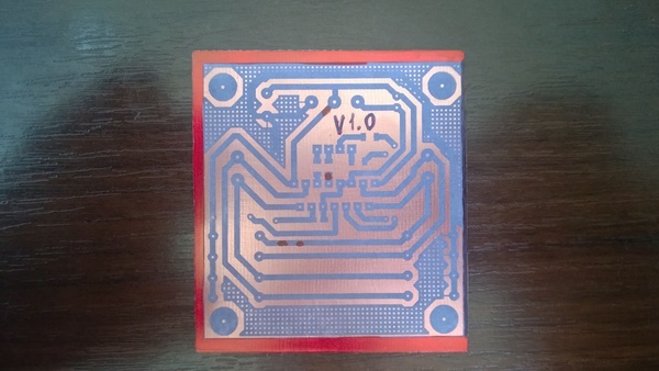
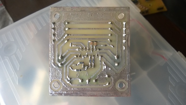
Optical Isolation Board Making
Moved with LUT and corrected with a marker:
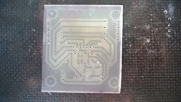
Etched:
Buzz:
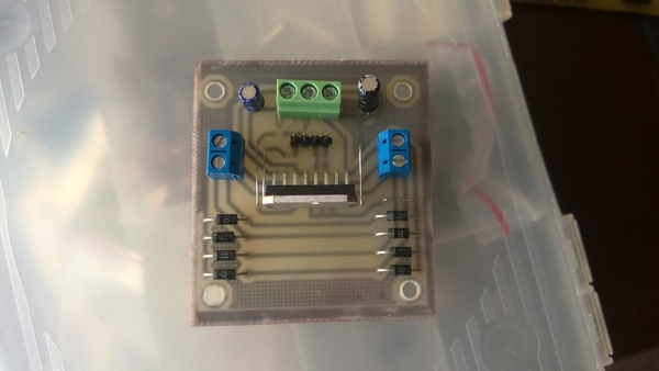
Assembled all electronics:
Machine assembly
The machine was assembled from plywood 10 mm thick and 18 mm planks. When assembling furniture guides were used, it was better not to find anything for the first time, and psychologically I was not ready to process at least the same metal corners.
At first there was such a construction:
The first version of the Z axis:
But as I understand it now, it was no good at all, everything drove, staggered. In general, about any rigidity and speech was not.
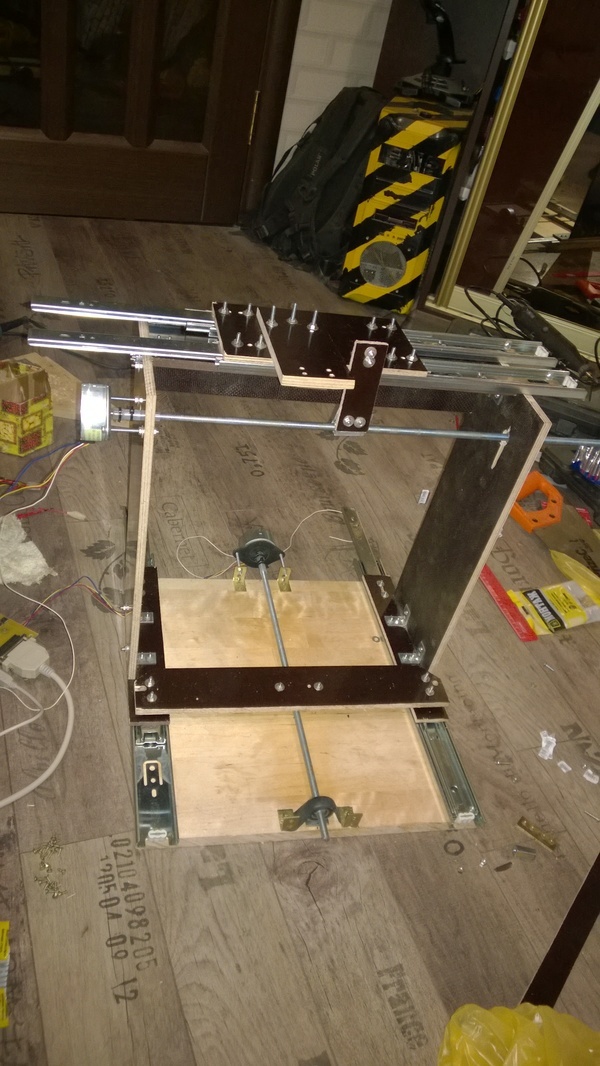
There was another attempt:
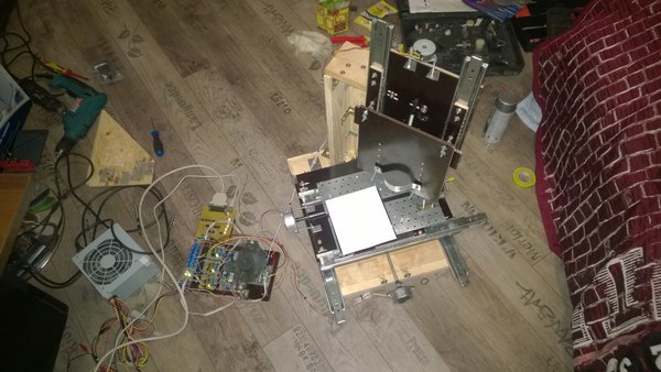
During which the X and Y axes were moved to a separate platform and turned into a movable table:
It was already better, but still very far from something that was not loose. As a result, came to this option:
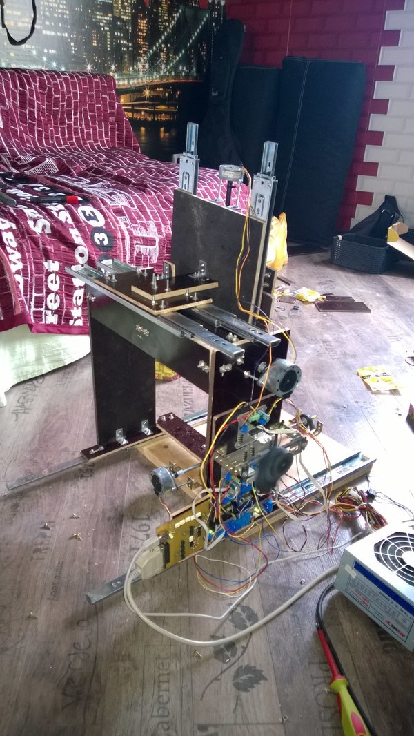
However, the Z axis is still twitching and bending too much. This time I sat down and thought well and had already taken up some design. The result was this design:
Equal-shelf aluminum corners with a shelf of 25 mm and a thickness of 2 mm were used as guides. Steel could not find. They would be many times better. Guides of industrial production, of course, still do not go to any comparison.
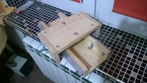
Moving carriage:
Assembled new Z axis:
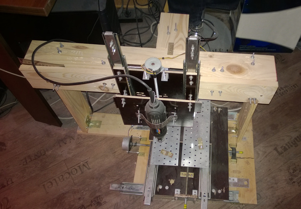
Result. You can see that the assembled axis, and the design as a whole, is still different even from the designed one. Nevertheless, to combine and center the axis when you only have a vernier caliper and a hand drill from a precise tool is not an easy task. For this, I had to rethink and experiment on the go:
Trying to milling something:
Even with so many if, even with such an imperfect construction, it turned out to create something working and the result I was impressed.
Control computer
The control software of CNC machines must operate on real-time systems in order to generate accurately synchronized signals. Therefore, Windows is not very good for this. Of course, for the correct operation, drivers are written that solve this problem, but it usually requires more resources and the stability of such a system is lower than real-time systems.
Processing was done under LinuxCNC. Installation and configuration should not cause great difficulties. On the program site there are already ready builds and source codes for gourmets. There are several ways to install: on an already installed system or from scratch with a configured OS. I chose the second option, since I am not so experienced in working with Linux, and there was not enough time to deal with the patching process. The second option is the usual Debian distribution with the RTC kernel and the LinuxCNC already installed.
After installation, it is necessary to adjust the axes of the machines: signal mapping, movement speed, acceleration values, and so on. The result is an output file to run, which, when started, will show the machine control program itself with the specified parameters.
Conclusion
As a result of the work done, there are still a lot of impressions left, as well as questions and tasks for improving the resulting machine.
- Increase the motor supply voltage from 12 V to their working 24 V
- Strengthen the structure, and ideally prepare a new design of the machine with a preliminary full design
- Add limit switches and emergency stop button
- Perform optimization of the operation of the controller SD
- Rebuild the machine electronics on one board with the exception of optocoupler board
- Replace the machine spindle with an appropriate target. That is, a highly revving and more powerful engine than the current Chinese engraver.
- Replace the motor on the Z axis, since the current motor is lower in power and the most loaded
The resulting machine has a working area greater than 270 mm in the X and Y axes, and about 150 mm in Z. The speeds of movement along the X and Y axes are more than 500 mm / s, and in Z and 300 mm / s. It is at 12 V operating voltage. That is half of their performance. There is room to grow.
What can be said with certainty - it was worth it. At least one task the machine will do well now: cutting boards. You can forget about etching and LUT. Cutting boards has, of course, its drawbacks, but it is better to have alternatives than the only option. The video of the work showed how the 3 mm mill machine milled the letter M, maybe with a low feed rate and layers of 0.1 mm, but this is also the result.
I don’t see much point in spreading any sources or PCB boards. The machine did not turn out suitable for any serious loads or rather stable and unique. However, this is not the last attempt to do anything and the next iteration of development is being prepared, I hope, a better one.
Source: https://habr.com/ru/post/394537/
All Articles