ESP8266 where to start or first experience
In this article I want to share the experience of what to do when the ESP8266 handkerchiefs fall into my hands for the first time. At once I will make a reservation that picking in such glands, as well as programming, is my hobby for my money and in my free time from the main activity. Therefore, I ask you to treat with a certain discount to the degree of criticism of this material.
Why did I decide to write this? It's simple: I killed 3 weeks of time to figure out where to start and how it works. In addition, I will try to collect a small catalog of links for working with ESP8266. I hope that this information will help you save at least a fraction of the time.
')
So let's get started!
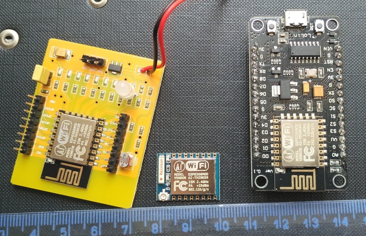
I ordered 3 options for boards on a well-known Chinese website:
The reasons why I took this zoo:
To begin with - check modules.
In all start-up instructions, they write that if you plug in the power and the “AI-THINKER xxxxxxx” WiFi network appeared, it means the device is working. It happened with my devices - they all created a WiFi network to which you could connect. Hooray! Earned! I was delighted, but early.
First I decided to experiment with the Yellow Board. The seller with the best price-rating indicator in the description of the goods had only pictures. And not a word of description. On the Russian-speaking resources there were references to this board, but I did not find any specifics about it. Some sellers I saw this instruction:
The inconsistency was that my network “AI-THINKER xxxxxxxxx” did not ask for a password, but the phone immediately connected to it. And the application at point-blank did not "see" ESP after connection. The RGB LED is blue with a jumper or green without it.

I guessed that, perhaps, the Chinese soldered - soldered, and forgot to flash (or crookedly asked). Therefore, I decided to sew myself. For firmware, I used the ESP8266 Flasher. And then the second surprise came out: no program recognized the board, did not respond to commands, the firmware was not flooded. I connected via Arduino and through the UART converter - nothing. The other two boards have already managed to reflash and blink the LED, and here it is deaf. Until I thought to call the contacts.
On this board, three pins for the firmware are displayed separately: TX, RX, GND. So it turned out that TX is divorced on the RX of the ESP-12 itself, respectively, the RX is on the TX. Those. it was just necessary to swap two wires: we connect the UART converter according to the following scheme to the separately placed three contacts:
Tx-tx
Rx-rx
GND-GND
Or Arduino:
Tx-rx
Rx-tx
GND-GND
After this discovery, the module came to life, the original firmware for flashing LEDs was found (AI-THINKER-IOT-2014-10-17 165528.bin) and stitched with the same ESP8266 Flasher. A password appeared on the access point, and the application immediately saw the Yellow card. The only caveat: for flashing it is necessary to install a jumper, for all other cases to remove. And do not forget to reboot the device after flashing.
Instructions for connecting ESP-07 (ESP-12) via a UART converter:

With the help of a soldering iron, the ESP-07 and the adapter were combined. I recommend the adapter because it further facilitates the connection by a solderless method using a breadboard and wires. In this case, for power, I used a step-down DC-DC converter from China. There were DS18B20 sensors available, and it was decided to connect them.
HomesSmart did not want to be set right away and the choice fell on such an example . I will not reprint the scheme and code - they are almost the same. It did not work immediately, but with Google and a tambourine it started and the data went to the People’s Monitoring.
Loaded the script via ESplorer .
Waiting for a compact power module 220AC - 3,3DC to optimize the number of wires.
This board was advised to immediately flash NodeMcu firmware, which was done through the NodeMcu flasher program. The firmware itself is assembled by the designer, which allows you to enable only the most necessary.
Next was supposed to connect and control 2-channel relay and control two sconces in the bedroom. Here I want to dwell on one nyance. The Chinese version of such a relay has a jumper JD-VCC - VCC - GND. By default, it is set to JD-VCC - VCC pins.

So, you should never install a perm on VCC - GND - arrange a short circuit! These three contacts are used for additional power supply of the relay, in cases where the control may not be sufficient to trigger the relay. The presence of a jumper indicates that power is supplied from the "control" contacts.
The script was used like this:
I could not re-find the link to the source. But the scheme is simple: connect Lolin to outputs D3 and D4 of relay 1 and relay 2 ( led1 = 3 led2 = 4 ). Then we go to the IP address issued by our router and see the page:

To my great regret, I have not yet figured out how to induce beauty, for example, to include a CSS-style file. The question is in the use of individual files in the output of the page, and not in the task of style.
I really hope that this information is useful at least for one person. And do not judge strictly for the first article.
Why did I decide to write this? It's simple: I killed 3 weeks of time to figure out where to start and how it works. In addition, I will try to collect a small catalog of links for working with ESP8266. I hope that this information will help you save at least a fraction of the time.
')
So let's get started!
I ordered 3 options for boards on a well-known Chinese website:
- ESP8266 WIFI Serial Wireless Dev Test Board based on ESP-12 (hereinafter referred to as the Yellow Board) ($ 3.12)
- ESP8266 ESP-07 with Adapter Plate For ESP8266 (hereinafter ESP-07) ($ 2.30)
- LoLin V3 NodeMcu Lua based on ESP-12 (hereinafter referred to as Lolin) ($ 3.12)
The reasons why I took this zoo:
- The Yellow board has LEDs built in which you can immediately blink, you can use not fabulous 3.3V for power supply, which you need to somehow get, but 3 AA batteries or by connecting 4.5V (which I did).
- LoLin bribed me by connecting with a micro cable and it doesn’t need any UART converters - it is immediately integrated into it based on the Chinese CH340 chip, for which you can easily find drivers like on win7x64 and on win10x64 (my cases), and Again, powered by a standard adapter with USB output, and not tricky 3.3V.
- Specifically, this ESP-07, I took a meteorological station. The mercury-analog thermometer has faded, nailing a new one is lazy, and it’s lying when heated from the wall of the house decently. For beginners, I recommend taking the Adapter Plate right away - the rise in price is only 20 cents, and there are much more amenities.
To begin with - check modules.
In all start-up instructions, they write that if you plug in the power and the “AI-THINKER xxxxxxx” WiFi network appeared, it means the device is working. It happened with my devices - they all created a WiFi network to which you could connect. Hooray! Earned! I was delighted, but early.
First I decided to experiment with the Yellow Board. The seller with the best price-rating indicator in the description of the goods had only pictures. And not a word of description. On the Russian-speaking resources there were references to this board, but I did not find any specifics about it. Some sellers I saw this instruction:
Instructions to the Yellow Board
1. Android phone installation IOT.APK, IOS client be released later
2. shorting cap
3. Replace the battery, mobile search network "AI-THINKER" router
4. join the router (the router module form) password is: ai-thinker
5. After the mobile phone.
6. Enter the “SSID” and “Password” in the “Configure Device”, then click on the router icon. again “discovered device” to achieve control in the LAN.
My free translation:
1. Install IOT.APK on a device with Wi-Fi running on Android OS (does not work on version 5.0 and higher!), The Client for IOS will be released later
2. On the board, you must remove the jumper that activates the firmware mode.
3. Restart the module (disconnect and connect the power) and after a minute, look for the AI-THINKER network on the Android device Wi-Fi
4. Connect to this network with the password "ai-thinker"
5. After that, launch the installed IOT application and click on the magnifying glass. The fee should be automatically determined. After that, move the sliders, click the switches and watch the LEDs on the board.
The inconsistency was that my network “AI-THINKER xxxxxxxxx” did not ask for a password, but the phone immediately connected to it. And the application at point-blank did not "see" ESP after connection. The RGB LED is blue with a jumper or green without it.
I guessed that, perhaps, the Chinese soldered - soldered, and forgot to flash (or crookedly asked). Therefore, I decided to sew myself. For firmware, I used the ESP8266 Flasher. And then the second surprise came out: no program recognized the board, did not respond to commands, the firmware was not flooded. I connected via Arduino and through the UART converter - nothing. The other two boards have already managed to reflash and blink the LED, and here it is deaf. Until I thought to call the contacts.
On this board, three pins for the firmware are displayed separately: TX, RX, GND. So it turned out that TX is divorced on the RX of the ESP-12 itself, respectively, the RX is on the TX. Those. it was just necessary to swap two wires: we connect the UART converter according to the following scheme to the separately placed three contacts:
Tx-tx
Rx-rx
GND-GND
Or Arduino:
Tx-rx
Rx-tx
GND-GND
After this discovery, the module came to life, the original firmware for flashing LEDs was found (AI-THINKER-IOT-2014-10-17 165528.bin) and stitched with the same ESP8266 Flasher. A password appeared on the access point, and the application immediately saw the Yellow card. The only caveat: for flashing it is necessary to install a jumper, for all other cases to remove. And do not forget to reboot the device after flashing.
ESP8266 ESP-07 with Adapter Plate
Instructions for connecting ESP-07 (ESP-12) via a UART converter:
- Red - power 3.3V;
- Black - GND;
- Yellow - on the side of the ESP8266 - RX, on the side of the USB-TTL - TX;
- Green - on the side of the ESP8266 - TX, on the side of the USB-TTL - RX;
- Orange - CH_PD (CHIP ENABLE) - should always be pulled up to power;
- Blue - GPIO0 - is connected via a switch to the ground to activate the module flashing mode. For a normal start of the GPIO0 module, you can leave it not connected;
- Gray - GPIO15 (MTDO, HSPICS) this pin must be pulled to the ground;
- If you connect to Arduino, then RX-RX, and TX-TX.
With the help of a soldering iron, the ESP-07 and the adapter were combined. I recommend the adapter because it further facilitates the connection by a solderless method using a breadboard and wires. In this case, for power, I used a step-down DC-DC converter from China. There were DS18B20 sensors available, and it was decided to connect them.
HomesSmart did not want to be set right away and the choice fell on such an example . I will not reprint the scheme and code - they are almost the same. It did not work immediately, but with Google and a tambourine it started and the data went to the People’s Monitoring.
Loaded the script via ESplorer .
It was on Arduino
Became on ESP8266
Waiting for a compact power module 220AC - 3,3DC to optimize the number of wires.
LoLin V3 NodeMcu (Lolin)
This board was advised to immediately flash NodeMcu firmware, which was done through the NodeMcu flasher program. The firmware itself is assembled by the designer, which allows you to enable only the most necessary.
Next was supposed to connect and control 2-channel relay and control two sconces in the bedroom. Here I want to dwell on one nyance. The Chinese version of such a relay has a jumper JD-VCC - VCC - GND. By default, it is set to JD-VCC - VCC pins.
So, you should never install a perm on VCC - GND - arrange a short circuit! These three contacts are used for additional power supply of the relay, in cases where the control may not be sufficient to trigger the relay. The presence of a jumper indicates that power is supplied from the "control" contacts.
The script was used like this:
Script text
#================= init.lua ================= -- ssid,pass = "SSID","PASSWORD"; if (file.open('wificonf') == true)then ssid = string.gsub(file.readline(), "\n", ""); pass = string.gsub(file.readline(), "\n", ""); file.close(); end wifi.setmode(wifi.STATION) wifi.sta.config(ssid,pass) wifi.sta.autoconnect(1); print('IP:',wifi.sta.getip()); --print('MAC:',wifi.sta.getmac()); led1 = 3 led2 = 4 gpio.mode(led1, gpio.OUTPUT) gpio.mode(led2, gpio.OUTPUT) restart=0; gpio.write(led1, gpio.HIGH); gpio.write(led2, gpio.HIGH); t=0 tmr.alarm(0,1000, 1, function() t=t+1 if t>999 then t=0 end end) srv=net.createServer(net.TCP, 1000) srv:listen(80,function(conn) conn:on("receive",function(client,request) -- _GET local buf = ""; local _, _, method, path, vars = string.find(request, "([AZ]+) (.+)?(.+) HTTP"); if(method == nil)then _, _, method, path = string.find(request, "([AZ]+) (.+) HTTP"); end local _GET = {} if (vars ~= nil)then for k, v in string.gmatch(vars, "(%w+)=(%w+)&*") do _GET[k] = v end end -- -- <html><body>, \ -- \, </body></html> conn:send('HTTP/1.1 200 OK\r\nConnection: keep-alive\r\nCache-Control: private, no-store\r\n\r\n\ <!DOCTYPE HTML>\ <html>\ <head>\ <meta charset="UTF-8" />\ <meta http-equiv="X-UA-Compatible" content="IE=edge,chrome=1"> \ <meta name="viewport" content="width=device-width, initial-scale=1.0"> \ <title>My control</title>\ </head><body>\ <div class="container">\ <section class="color-1">\ <p>\ <a href=\"?pin=ON1\"><button class="btn btn-4 btn-4a">Back ON</button></a>\ <a href=\"?pin=ON2\"><button class="btn btn-4 btn-4a">Bra ON</button></a>\ </p>\ <p>\ <a href=\"?pin=OFF1\"><button class="btn btn-5 btn-5a">Back OFF</button></a>\ <a href=\"?pin=OFF2\"><button class="btn btn-5 btn-5a">Bra OFF</button></a>\ </p>\ </section>\ </div>\ </body></html>') -- -- local _on,_off = "","" if(_GET.pin == "ON1")then gpio.write(led1, gpio.LOW); elseif(_GET.pin == "OFF1")then gpio.write(led1, gpio.HIGH); elseif(_GET.pin == "ON2")then gpio.write(led2, gpio.LOW); elseif(_GET.pin == "OFF2")then gpio.write(led2, gpio.HIGH); end conn:on("sent",function(conn) conn:close() end) collectgarbage(); end) end) #======================================== I could not re-find the link to the source. But the scheme is simple: connect Lolin to outputs D3 and D4 of relay 1 and relay 2 ( led1 = 3 led2 = 4 ). Then we go to the IP address issued by our router and see the page:
To my great regret, I have not yet figured out how to induce beauty, for example, to include a CSS-style file. The question is in the use of individual files in the output of the page, and not in the task of style.
I really hope that this information is useful at least for one person. And do not judge strictly for the first article.
Links
- esp8266.ru - a very extensive resource on ESP8266
- NodeMcu flasher (ESP8266 Flasher)
- NodeMcu constructor
- CH340 driver (for Windows)
- Article " ESP8266 - connecting and updating firmware "
- AI-THINKER-IOT-2014-10-17 165528.bin - firmware for the Yellow Card
- Esplorer
- People monitoring
- How to send DS18B20 sensor data to People Monitoring
- Homes-smart project
Source: https://habr.com/ru/post/394535/
All Articles