Once again about drawing on the oscilloscope screen
 The image on the screen of the analog oscilloscope causes a sense of magic and magic, as if looking through a small window into the mysterious green world. This is especially felt if not the usual sinusoid or “saw” is drawn on the screen, but rather Lissajous figures or something else more exotic. There are a considerable number of publications devoted to this topic. In particular, she was touched by an article on Habré: We draw on the oscilloscope screen , which tells about the device based on the Arduino, which draws a very effective video.
However, to draw complex images you need an oscilloscope with two inputs: X and Y. What should I do if I only have an oscilloscope with an input Y on my hands (as, for example, in my good old C1-94), and see the picture on my screen with my own eyes, still want to?
It turned out that the construction for drawing numbers on the oscilloscope screen was described as early as the early 80s, in an article by V. Kosinov in Radio No. 11 magazine for 1981. And most importantly, it does not need X-axis input!
The design uses a raster drawing method. The beam moves horizontally with a sweep generator and draws a single raster line in one pass. Each line has its own voltage level at input Y. To extinguish, the beam is output outside the screen by applying a sufficiently high voltage to the input. The transition to a new line occurs after a pulse is applied to the external synchronization input.
')
An example of a graph of a signal that draws a four-line bitmap image of the symbols “with o” is shown in the figure.
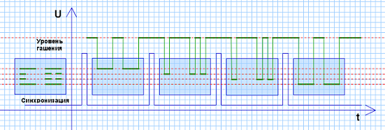
The blue rectangle represents the frames displayed on the oscilloscope screen, and the final image is placed on the left.
The device is quite complex and contains 23 chips. Later, in the magazine Radio No. 7 for 2000, an article by A. Marievich was published, in which, thanks to the new elementary base that became available at that time, the device was simplified. But even in it the number of microcircuits is too large to realize the construction in a couple of hours of free time in the evening of the working day - 8 pieces, plus the need to program the ROM.
Now the idea of further simplification suggests itself - the microcontroller will do an excellent job with generating the required signal at the oscilloscope input. The first version of the device was performed on the PIC12F629, supplemented by a simple DAC on resistors. The assembler code successfully coped with drawing numbers, but it turned out to be rather “heavy”. As a result, the project did not receive further development and for some time was abandoned.
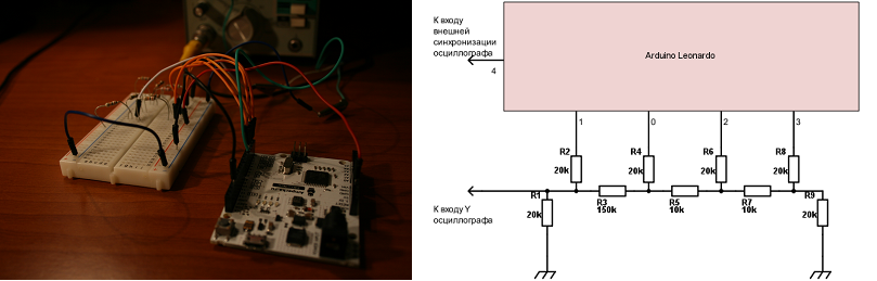
Interest revived after meeting with the Arduino and the acquisition of the Arduino Leonardo board. Thanks to the simplicity of programming, a project containing a set of functions for displaying an arbitrary string of 7 Latin letters or numbers on the oscilloscope screen, as well as drawing 8x35 pixels of graphic primitives on the screen: dots and rectangles on the screen, turned out to be short. An analog signal is generated using the same simplest DAC on nine resistors assembled on a breadboard.
The work of the functions is demonstrated by the video:
And in order to give the project an applied meaning, allowing you to boldly meet the question: “How to apply it in agriculture?”, A time counter was added to the code, two buttons: “Start / Stop”, “Reset”, and the oscilloscope acquired the additional function of a stopwatch:
Wiring diagrams and project source codes are available on GitHub .
Source: https://habr.com/ru/post/394531/
All Articles