"Electricity in the squares" or how I did an electronic designer from scrap materials
The idea of creating an electronic designer stirred my thoughts for a long time. As a child I had a designer EKON-1 and wanted to create something similar, but at the modern level. In the market the ball is ruled by Expert, there are also examples of modular constructors abroad, but the price and the course are not pleasing to the eye.
On the other hand, there were interesting developments in the USSR (one of them still lives in Germany and is being produced):
www.rw6ase.narod.ru/00/rk/radiokubiki.html
www.rw6ase.narod.ru/00/rk/rad_kub.html
www.rw6ase.narod.ru/00/rk/ekon01.html
www.rw6ase.narod.ru/00/rk/ked.html
www.rw6ase.narod.ru/00/rk/mozaika.html
www.rw6ase.narod.ru/00/rk/mrk2.html
www.rw6ase.narod.ru/00/rk/rk1.html
el-constructor.ru
')
I also wanted something “warm” in materials like wood. In 2014, within the framework of the PROPORTURE project , the idea of electronic cubes was born, which in 2015 even received a prize from AIDT for an idea at one of the selection stages of the Startup Tour.
Also at this time I came up with a logical board game "Chain", which allowed to play "electrical circuits". The game can be freely downloaded and printed by reference .
Time went by. The cubes had to be put aside, since the price of the magnets of the necessary power made them quite expensive. The game "Chain" waited for its turn in the finalization.
In 2016, I decided to return to the project and “got” the cubes. The first idea was to use the same cubes, but to make fasteners of the type of spring contacts and glue together a cardboard box with cells, on the walls of which there would be contacts:
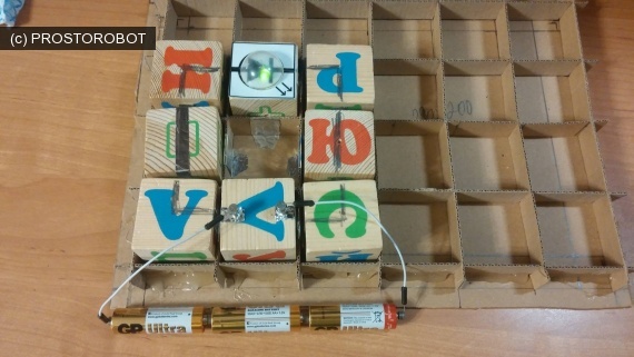
The design turned out to be cumbersome, but due to the low stiffness of the walls, the cubes did not give the desired quality of contact.
Engineering thought moved on. A small digression on the choice of material. You can reasonably say why I did not use 3D printing or laser cutting? The answer is simple - I don’t have a 3D printer (or rather, there’s no place to put it in an apartment), and the nearest reasonable cut in price and quality is 500 kilometers from my city. Even to find thin plywood turned out to be an unreal quest, not to mention a special model. Plus, I have long wanted to try the usual stuff for board game lovers - cardboard.
The second option was to apply the method that I used earlier when designing the Skratchduino - that is, 2.5 modeling the constructor blocks themselves and mounting magnets. This method did not require powerful expensive magnets, but at my place there was a supply of 5 mm cylindrical magnets of different heights (2 and 3 mm).
It was also decided to start by making a “physical” counterpart of the board game “Chain”, since it required only 4x4 fields, and then collecting all the “cones”, making the assembly field larger (at least 4x6, and better 6x8).
There was one more question - what to make contacts. The ideal is a copper strip. The problem of the ideal is where to get it. Also, copper is non-magnetic and it would be necessary to put magnets on the field and on the blocks. Taking into account the fact that magnets would have to be more powerful for placement under the contacts (and this means and time to send), the search for suitable material continued. And the look fell on the staples. The houses were staples of different sizes, they were steel (that is, they carried out current and were magnetised) and there were many of them.
As a result, the list of necessary components was determined - brackets for stapler No. 35 (26/6 1 pack), neodymium magnets C-5x2-N35 and C-5x3-N35 with nickel coating (conductive), cardboard (micro-corrugated cardboard left over from under photos and boxes), wire, solder, LED, resistor, microlamp, diode and button. It was decided to use PVA glue for gluing parts, and a usual hole punch came up for punching holes for magnets.
The materials were determined, the dimensions were also (cell 40x40 mm, block 38x38 mm) and the immediate process began.
The field is a sheet of cardboard, marked up on squares 40x40 mm, the side faces of which are “prostaplereny” in the center with a block of clips.
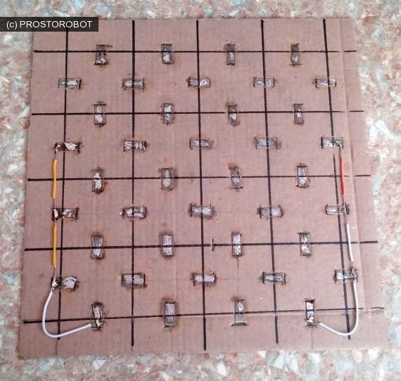
I took the staples the same as for the blocks-cubes, but then I made the first mistake. I did not see that the staples were covered with a non-conductive material on top, so I had to protect them later. I also tried to round them up (which did not work out very well) and the size of the staples should be taken more so as not to depend on the errors in the manufacture of the blocks. If you decide to repeat this construction, take the brackets about 20 mm wide and make a block 1 cm wide.
Staples were inserted into the slots of the cardboard and bent on the reverse side. In the photo, the side wires are needed to “imitate” the common bus of the chain game “Chain” and in the final version of the constructor they will be replaced with blocks.
So, as a result of this hard work, we have a field with contact pads, to which our contact magnets are well magnetized.
Now it was necessary to make the blocks themselves with conductors and radio components. The problem was that in the board game there were elements with a cross-shaped intersection and crossing conductors, and it was impossible to ensure the contact of all 4 magnets (remember how many points the plane passes through). Therefore, it was decided to abandon such blocks and make maxim T-shaped elements. For intersecting elements, I plan to use special bridges-wires in the future.
The block itself consists of three squares of cardboard measuring 38x38 mm. On average, holes are made for magnets and slots for brackets. On it, above, the second square is glued onto the PVA glue with only slots for brackets. After that, a small magnet of 5x2 mm is placed in the hole, and the top is closed with a block of clips that are bent on the other side. Radio components or conductors are soldered to them. On the other hand we put the magnets 5x3 mm and glue the square with the holes. Due to the fact that the magnets "stick" to the magnets under the brackets, they are very tight and do not stay on the field.
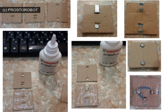
Thus, we produce blanks with two and three magnetic pads. Then we solder the conductors or radio components.

We glue cardboard stripes on top (two or three layers depending on the height of the parts) and close all with a cardboard “lid” on which we draw a designation with a marker (straight conductor, corner, T-shaped or radio element).
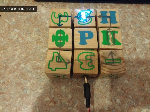
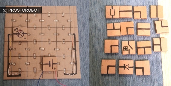
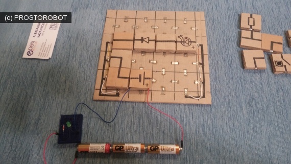
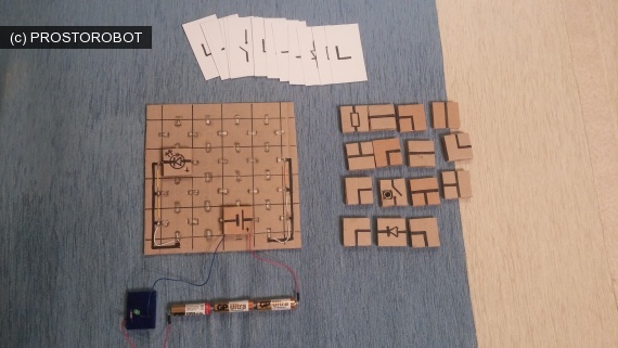
As a result, we received such a field and a set of details. I did not begin to make the battery in the form of a block (although there is an idea to use a 5 V tablet in the future), but I made an element with two wires to which 3 batteries are connected.
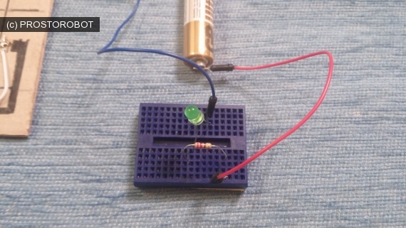
In the process of testing, it turned out that the light did not light up if there was an LED or a resistor in the circuit, and the LED could not be used without resistance (the smell of burning plastic clearly showed this). Therefore, to simulate the gameplay, it was decided to assemble a “signal” circuit from another LED and a resistor on the breadboard, and to simplify the game a little, leaving only one LED that needs to be “lit” to win. This turned out to be not critical and this option is even more interesting, since it allowed changing the starting conditions of the game. The game “Chain” in the desktop version will also be processed and transferred to a larger field, with several lamps and LEDs and various starting positions.
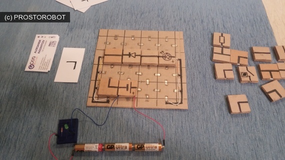
Cards were also prepared for the game, pulling out which the player understands which element he can use. Below is the final photo of the radio constructor game, as well as the game process.
On the other hand, there were interesting developments in the USSR (one of them still lives in Germany and is being produced):
www.rw6ase.narod.ru/00/rk/radiokubiki.html
www.rw6ase.narod.ru/00/rk/rad_kub.html
www.rw6ase.narod.ru/00/rk/ekon01.html
www.rw6ase.narod.ru/00/rk/ked.html
www.rw6ase.narod.ru/00/rk/mozaika.html
www.rw6ase.narod.ru/00/rk/mrk2.html
www.rw6ase.narod.ru/00/rk/rk1.html
el-constructor.ru
')
I also wanted something “warm” in materials like wood. In 2014, within the framework of the PROPORTURE project , the idea of electronic cubes was born, which in 2015 even received a prize from AIDT for an idea at one of the selection stages of the Startup Tour.
Also at this time I came up with a logical board game "Chain", which allowed to play "electrical circuits". The game can be freely downloaded and printed by reference .
Time went by. The cubes had to be put aside, since the price of the magnets of the necessary power made them quite expensive. The game "Chain" waited for its turn in the finalization.
In 2016, I decided to return to the project and “got” the cubes. The first idea was to use the same cubes, but to make fasteners of the type of spring contacts and glue together a cardboard box with cells, on the walls of which there would be contacts:
The design turned out to be cumbersome, but due to the low stiffness of the walls, the cubes did not give the desired quality of contact.
Engineering thought moved on. A small digression on the choice of material. You can reasonably say why I did not use 3D printing or laser cutting? The answer is simple - I don’t have a 3D printer (or rather, there’s no place to put it in an apartment), and the nearest reasonable cut in price and quality is 500 kilometers from my city. Even to find thin plywood turned out to be an unreal quest, not to mention a special model. Plus, I have long wanted to try the usual stuff for board game lovers - cardboard.
The second option was to apply the method that I used earlier when designing the Skratchduino - that is, 2.5 modeling the constructor blocks themselves and mounting magnets. This method did not require powerful expensive magnets, but at my place there was a supply of 5 mm cylindrical magnets of different heights (2 and 3 mm).
It was also decided to start by making a “physical” counterpart of the board game “Chain”, since it required only 4x4 fields, and then collecting all the “cones”, making the assembly field larger (at least 4x6, and better 6x8).
There was one more question - what to make contacts. The ideal is a copper strip. The problem of the ideal is where to get it. Also, copper is non-magnetic and it would be necessary to put magnets on the field and on the blocks. Taking into account the fact that magnets would have to be more powerful for placement under the contacts (and this means and time to send), the search for suitable material continued. And the look fell on the staples. The houses were staples of different sizes, they were steel (that is, they carried out current and were magnetised) and there were many of them.
As a result, the list of necessary components was determined - brackets for stapler No. 35 (26/6 1 pack), neodymium magnets C-5x2-N35 and C-5x3-N35 with nickel coating (conductive), cardboard (micro-corrugated cardboard left over from under photos and boxes), wire, solder, LED, resistor, microlamp, diode and button. It was decided to use PVA glue for gluing parts, and a usual hole punch came up for punching holes for magnets.
The materials were determined, the dimensions were also (cell 40x40 mm, block 38x38 mm) and the immediate process began.
The field is a sheet of cardboard, marked up on squares 40x40 mm, the side faces of which are “prostaplereny” in the center with a block of clips.
I took the staples the same as for the blocks-cubes, but then I made the first mistake. I did not see that the staples were covered with a non-conductive material on top, so I had to protect them later. I also tried to round them up (which did not work out very well) and the size of the staples should be taken more so as not to depend on the errors in the manufacture of the blocks. If you decide to repeat this construction, take the brackets about 20 mm wide and make a block 1 cm wide.
Staples were inserted into the slots of the cardboard and bent on the reverse side. In the photo, the side wires are needed to “imitate” the common bus of the chain game “Chain” and in the final version of the constructor they will be replaced with blocks.
So, as a result of this hard work, we have a field with contact pads, to which our contact magnets are well magnetized.
Now it was necessary to make the blocks themselves with conductors and radio components. The problem was that in the board game there were elements with a cross-shaped intersection and crossing conductors, and it was impossible to ensure the contact of all 4 magnets (remember how many points the plane passes through). Therefore, it was decided to abandon such blocks and make maxim T-shaped elements. For intersecting elements, I plan to use special bridges-wires in the future.
The block itself consists of three squares of cardboard measuring 38x38 mm. On average, holes are made for magnets and slots for brackets. On it, above, the second square is glued onto the PVA glue with only slots for brackets. After that, a small magnet of 5x2 mm is placed in the hole, and the top is closed with a block of clips that are bent on the other side. Radio components or conductors are soldered to them. On the other hand we put the magnets 5x3 mm and glue the square with the holes. Due to the fact that the magnets "stick" to the magnets under the brackets, they are very tight and do not stay on the field.
Thus, we produce blanks with two and three magnetic pads. Then we solder the conductors or radio components.
We glue cardboard stripes on top (two or three layers depending on the height of the parts) and close all with a cardboard “lid” on which we draw a designation with a marker (straight conductor, corner, T-shaped or radio element).
As a result, we received such a field and a set of details. I did not begin to make the battery in the form of a block (although there is an idea to use a 5 V tablet in the future), but I made an element with two wires to which 3 batteries are connected.
In the process of testing, it turned out that the light did not light up if there was an LED or a resistor in the circuit, and the LED could not be used without resistance (the smell of burning plastic clearly showed this). Therefore, to simulate the gameplay, it was decided to assemble a “signal” circuit from another LED and a resistor on the breadboard, and to simplify the game a little, leaving only one LED that needs to be “lit” to win. This turned out to be not critical and this option is even more interesting, since it allowed changing the starting conditions of the game. The game “Chain” in the desktop version will also be processed and transferred to a larger field, with several lamps and LEDs and various starting positions.
Cards were also prepared for the game, pulling out which the player understands which element he can use. Below is the final photo of the radio constructor game, as well as the game process.
Source: https://habr.com/ru/post/394435/
All Articles