Brain system
Recently, various kinds of intellectual games are gaining popularity: “What? Where? When? ”,“ Melotrek ”,“ Brain-ring ”. But for some types of games, one cannot do without a special system that will control the course of the game. Within the course project, we decided to try to make our own brain system.
Before that, we never encountered Arduino or something hardware, but looking at how friends and acquaintances at the university easily assembled devices, we wanted to try and we could do something of our own. Since we were far enough away from this topic, our manager put the offer to assemble the brain system, saying that this would be a good start for us. Surprisingly, this is what happened.
To begin with, we determined the goal: the brain system should give a sound signal indicating the beginning of the time of the question round and a signal indicating the end of the time of the question round, and should also signal to the leader that the player is ready to give an answer. If one player has pressed a button, then the other buttons are blocked. It should also be possible to select the game mode.
')
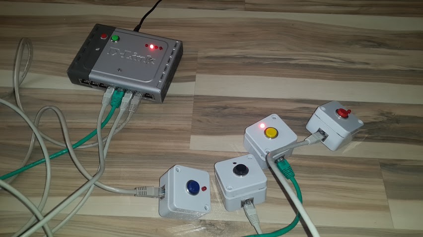
It is worth saying that the system can be divided into 3 blocks: the main module, the buttons of the players (4 pieces) and connecting cables. The system contains 4 player buttons. If the player managed to press before the others, then the LED on the button lights up.
The console lead. If a player has pressed a button on his console, then on the main unit the diode corresponding to the player’s button lights up. This module selects the game mode. The facilitator has two Start and Reset buttons. Depending on the game using these buttons turns on and resets the timer.
Signals come to Arduino from buttons. If the button is pressed, the diode on the button and on the master console lights up and the buzzer sounds. This is the main concept.
The buttons and the master console are connected via an Ethernet cable. A button goes to the ground, a logical unit and a signal that turns the LED on and off, and a signal comes from the button to the main module by pressing the button.
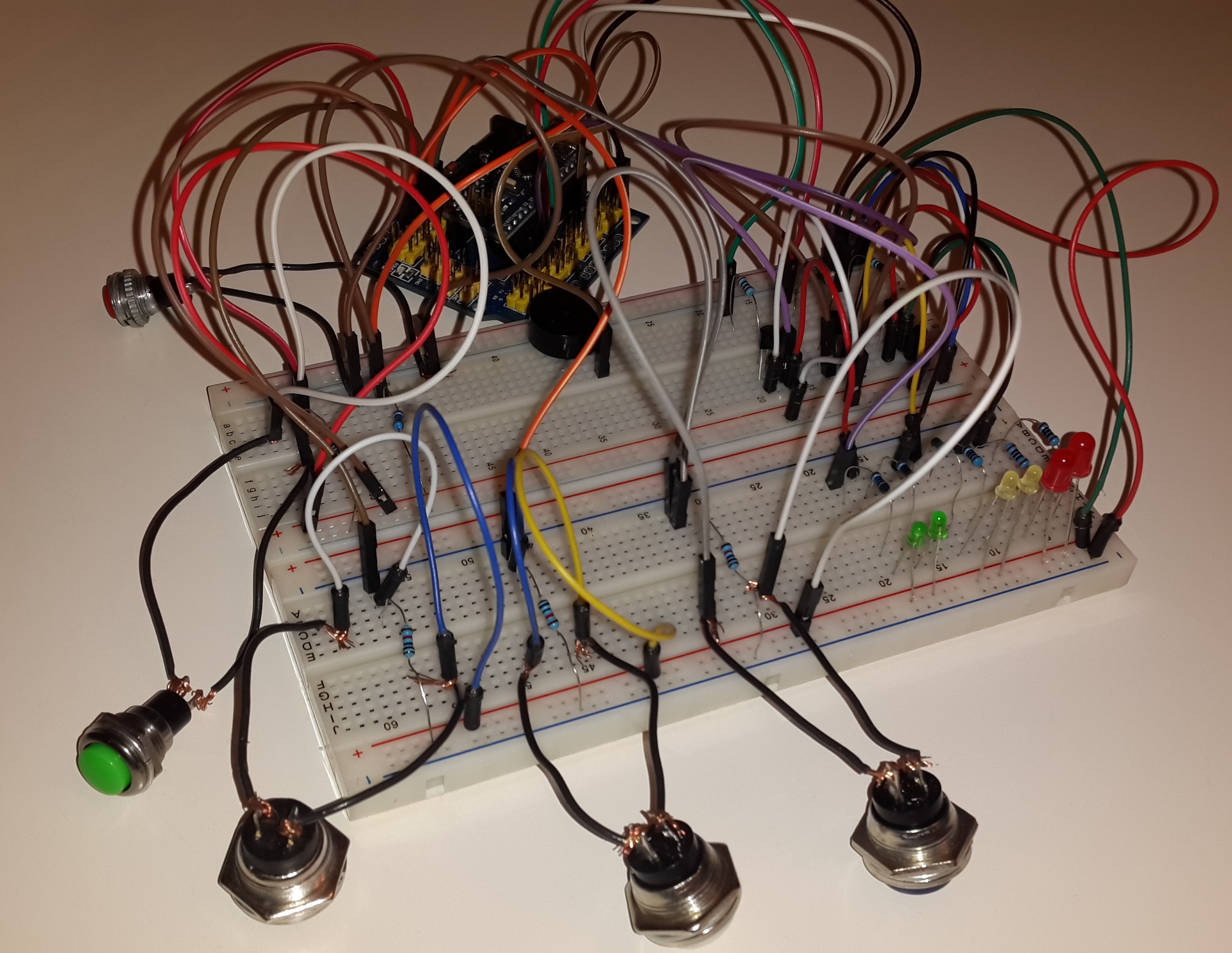
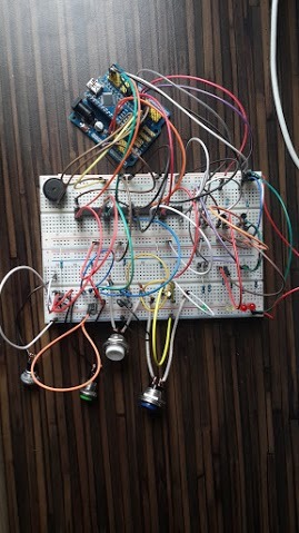
We started with the simplest. On the breadboard board assembled circuit, which includes a diode. It all worked! Moving on. Connected Arduino and buttons, when clicked on which the diodes light up. And here we are faced with the problem of bounce buttons.
In the buttons you need to remove the signal bounce, otherwise the system will think that the button is pressed many times. For the players' buttons, this is not very scary, we still catch the first press, but on the presenter’s start button we have to get rid of the bounce, because in the brain-ring you need to know how many times Start is pressed. For this purpose, the Schmitt trigger, a capacitor and a resistor are included in the button circuit. About bounce can be read here .
Both the buttons and the main module use LEDs. But 5V is too much voltage for them. Therefore, resistors are connected in series to prevent the diodes from burning. Calculate the resistance of resistors here . Due to the fact that all the LEDs are the same, we needed 8 resistors of 100 Ohms.

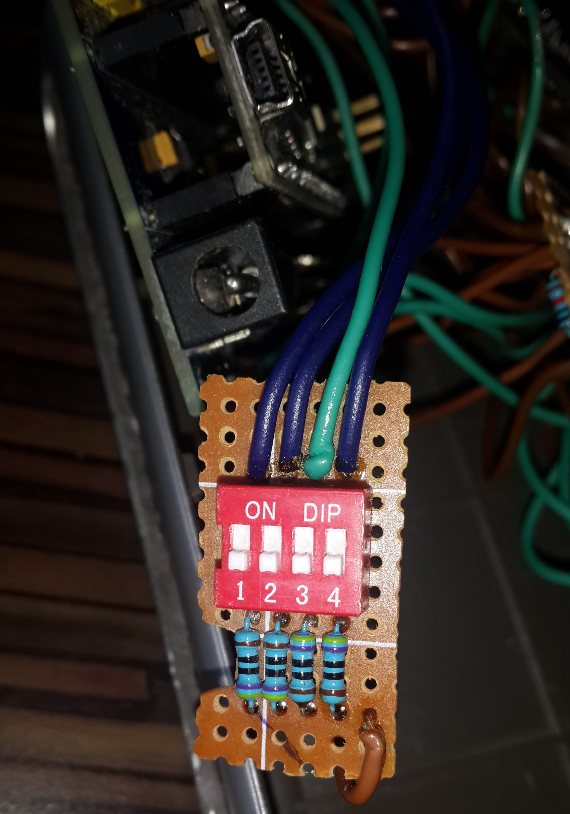
Game mode is selected using DIP-SWITCH:
Laziness is the key to success.
In parallel with the development of the scheme was written code. It was obvious that button presses should be handled through interrupts. After reading about the 2 external interrupts INT0 and INT1, we were upset because for as many as 6 buttons of two interrupts is not enough and we will have to increase the bit width through the register. Since we faced hardware things live for the first time, it was all difficult and incomprehensible for us. In general, we are not very happy about this fact. Not believing that our problem could not be solved in any other way, we came across Pin Change Interrupt Requests, which were ideally suited for our project. No registers!
You can get acquainted with interruptions here .
In our brain system, the SET and RESET buttons correspond to the D8 and D9 pins, and the user buttons to A0-A3. Therefore, we have defined only two interrupt handlers for each of the used interrupt groups.
Interrupts can be defined for each group and each pin separately. This is done by the control and mask registers, in which the corresponding values must be set. Read more about configuring and resolving interrupts here .
Interrupt handlers interrogate the pins in turn to determine which button was pressed. This situation is one of the limitations of these interrupts. The brain system must respond to button presses, so the pin value is compared to the HIGH level (that is, the button was pressed) in the interrupt handler.
All code is here .
We saw the soldering iron for the first time, so we started with a traditional diode. Soldered - the diode caught fire! Then they soldered the buttons. Checking whether everything was done correctly was difficult enough, because the main module was still on the breadboard.

Solder buttons lead, diodes, game mode switch. In the process, we realized that it was possible to get by with one Schmitt trigger. Then it should be transferred to the main module, bring the button outputs to it via a network cable, and send signals from its output to the Arduino.

In general, the main unit was ready. But still he was not connected with the buttons of the players. The basis of the main unit, we took the native board from the router, in which it was advantageous to use RJ-45 connectors. Although we regretted this a little, for cutting the board and soldering the contacts in the second circle is not the most pleasant thing. But everything went quite well.
We used for transmission logical 1 white-orange conductor, for logical 0 - orange, the signal to the diode - white-green and the signal from the button - green. Although you can use any, the main thing is to check which cable is used, because there are various options for crimping.
Now the main module and buttons were connected and the system was almost ready, but there was one bug that was not on the breadboard. If the button was not connected to the main module, the system thought that this button was pressed. On the Internet, we found a solution - a tightening resistor.
In order not to receive “no” signals to Arduino (when the button is not connected at all) in the main module you need to put a clamping resistor (from 10 kOhm) to each button output. When the open circuit unwanted current will go through the resistor to the ground, and when closed due to the large resistance of the resistor, the signal will go to the input contact.
After solving this problem, everything worked.

Features of the brain ring. If the start was not pressed, the system determines the pressing of the buttons as a false start. If the start is pressed for the first time, the system will wait 20 seconds for pressing the buttons, after the time has elapsed, the system will beep. If during this time the team still knows the correct answer and presses the button, then the corresponding signal sounds, and the timer in turn stops. In accordance with the rules, in the event of an incorrect response, other teams should be able to respond. To do this, after a second press on the start, the timer will start for 10 seconds. The reset button resets the system, it is pressed before reading the next question.
After pressing Start, a beep sounds. A beep sounds after 50 and 60 seconds. In the rest of the games, only button presses are trapped. Thanks to the convenience of working with Arduino, you can implement other games: change the timer, allow false start, etc. This can be done by adding the appropriate code.


It works and thank God. Since this was our first hardware experience, we are pleased with the results. And not only by the fact that everything worked connected on the breadboard, but also as a fully assembled device. A full-fledged brain-system with modes, players and moderators has been released. As an enhancement to the system, you can add an outlet for the speakers so that you can play in big tournaments.
As for the Arduino board, it was easy and pleasant to work. On the Internet, there is enough information and simple tutorials on assembling useful and interesting things that are not the easiest for an unknowing person. This may well turn into a hobby.
Oksana Kozlova and Marina Bardiyan took part in the project.
Before that, we never encountered Arduino or something hardware, but looking at how friends and acquaintances at the university easily assembled devices, we wanted to try and we could do something of our own. Since we were far enough away from this topic, our manager put the offer to assemble the brain system, saying that this would be a good start for us. Surprisingly, this is what happened.
To begin with, we determined the goal: the brain system should give a sound signal indicating the beginning of the time of the question round and a signal indicating the end of the time of the question round, and should also signal to the leader that the player is ready to give an answer. If one player has pressed a button, then the other buttons are blocked. It should also be possible to select the game mode.
')
Required components
- Arduino nano
- Speaker
- LEDs 8 pcs.
- Buttons 4 pcs. for players and 2 for lead
- Idle router
- Dip switch
- Resistors:
- 8 pieces - 100 Ohm (for diodes)
- 6 pieces - 10 kΩ (pull-down resistors)
- 6 pieces - 1 kOhm for bounce
- 4 things. - 470 ohms for DIP (optional)
- 5 pieces. - Schmitt trigger (but you can do with one)
- Capacitors - 6 pcs. 1 microfarad
- Ethernet cable 4 pcs.
- RJ-45 connectors - 4pcs.
- Button case
System structure
It is worth saying that the system can be divided into 3 blocks: the main module, the buttons of the players (4 pieces) and connecting cables. The system contains 4 player buttons. If the player managed to press before the others, then the LED on the button lights up.
The console lead. If a player has pressed a button on his console, then on the main unit the diode corresponding to the player’s button lights up. This module selects the game mode. The facilitator has two Start and Reset buttons. Depending on the game using these buttons turns on and resets the timer.
Signals come to Arduino from buttons. If the button is pressed, the diode on the button and on the master console lights up and the buzzer sounds. This is the main concept.
The buttons and the master console are connected via an Ethernet cable. A button goes to the ground, a logical unit and a signal that turns the LED on and off, and a signal comes from the button to the main module by pressing the button.
Start of development
We started with the simplest. On the breadboard board assembled circuit, which includes a diode. It all worked! Moving on. Connected Arduino and buttons, when clicked on which the diodes light up. And here we are faced with the problem of bounce buttons.
In the buttons you need to remove the signal bounce, otherwise the system will think that the button is pressed many times. For the players' buttons, this is not very scary, we still catch the first press, but on the presenter’s start button we have to get rid of the bounce, because in the brain-ring you need to know how many times Start is pressed. For this purpose, the Schmitt trigger, a capacitor and a resistor are included in the button circuit. About bounce can be read here .
Both the buttons and the main module use LEDs. But 5V is too much voltage for them. Therefore, resistors are connected in series to prevent the diodes from burning. Calculate the resistance of resistors here . Due to the fact that all the LEDs are the same, we needed 8 resistors of 100 Ohms.
Game mode is selected using DIP-SWITCH:
- Brain Ring
- What? Where? When?
- Erudite quartet, Troika, Own game (the system in these games is the same)
Software part
Laziness is the key to success.
In parallel with the development of the scheme was written code. It was obvious that button presses should be handled through interrupts. After reading about the 2 external interrupts INT0 and INT1, we were upset because for as many as 6 buttons of two interrupts is not enough and we will have to increase the bit width through the register. Since we faced hardware things live for the first time, it was all difficult and incomprehensible for us. In general, we are not very happy about this fact. Not believing that our problem could not be solved in any other way, we came across Pin Change Interrupt Requests, which were ideally suited for our project. No registers!
You can get acquainted with interruptions here .
In our brain system, the SET and RESET buttons correspond to the D8 and D9 pins, and the user buttons to A0-A3. Therefore, we have defined only two interrupt handlers for each of the used interrupt groups.
- ISR (PCINT0_vect) - for the master buttons.
- ISR (PCINT1_vect) - for custom buttons.
Interrupts can be defined for each group and each pin separately. This is done by the control and mask registers, in which the corresponding values must be set. Read more about configuring and resolving interrupts here .
Interrupt handlers interrogate the pins in turn to determine which button was pressed. This situation is one of the limitations of these interrupts. The brain system must respond to button presses, so the pin value is compared to the HIGH level (that is, the button was pressed) in the interrupt handler.
Interrupt Setup
ISR(PCINT0_vect) { noInterrupts(); isPushed = false; if (digitalRead(ADMIN_BUTTON_SET) == HIGH ) { gameMode->Set(); Timer1.attachInterrupt(TimerInterrupt); gameMode->SetFalseStart(false); } if (digitalRead(ADMIN_BUTTON_RESET) == HIGH) { Timer1.stop(); gameMode->Reset(); gameMode->SetFalseStart(true); } interrupts(); } ISR(PCINT1_vect){ noInterrupts(); if (isPushed == false){ for (int i = 0; i < ARRAY_SIZE(ARRAY_USER_BUTTON); i++){ if (digitalRead(ARRAY_USER_BUTTON[i]) == HIGH){ isPushed = gameMode->UserButtonPushed(ARRAY_LED[i]); } } } interrupts(); } All code is here .
Installation
We saw the soldering iron for the first time, so we started with a traditional diode. Soldered - the diode caught fire! Then they soldered the buttons. Checking whether everything was done correctly was difficult enough, because the main module was still on the breadboard.
Solder buttons lead, diodes, game mode switch. In the process, we realized that it was possible to get by with one Schmitt trigger. Then it should be transferred to the main module, bring the button outputs to it via a network cable, and send signals from its output to the Arduino.
In general, the main unit was ready. But still he was not connected with the buttons of the players. The basis of the main unit, we took the native board from the router, in which it was advantageous to use RJ-45 connectors. Although we regretted this a little, for cutting the board and soldering the contacts in the second circle is not the most pleasant thing. But everything went quite well.
We used for transmission logical 1 white-orange conductor, for logical 0 - orange, the signal to the diode - white-green and the signal from the button - green. Although you can use any, the main thing is to check which cable is used, because there are various options for crimping.
Now the main module and buttons were connected and the system was almost ready, but there was one bug that was not on the breadboard. If the button was not connected to the main module, the system thought that this button was pressed. On the Internet, we found a solution - a tightening resistor.
In order not to receive “no” signals to Arduino (when the button is not connected at all) in the main module you need to put a clamping resistor (from 10 kOhm) to each button output. When the open circuit unwanted current will go through the resistor to the ground, and when closed due to the large resistance of the resistor, the signal will go to the input contact.
After solving this problem, everything worked.
Features of game modes
Features of the brain ring. If the start was not pressed, the system determines the pressing of the buttons as a false start. If the start is pressed for the first time, the system will wait 20 seconds for pressing the buttons, after the time has elapsed, the system will beep. If during this time the team still knows the correct answer and presses the button, then the corresponding signal sounds, and the timer in turn stops. In accordance with the rules, in the event of an incorrect response, other teams should be able to respond. To do this, after a second press on the start, the timer will start for 10 seconds. The reset button resets the system, it is pressed before reading the next question.
Features What? Where? When?
After pressing Start, a beep sounds. A beep sounds after 50 and 60 seconds. In the rest of the games, only button presses are trapped. Thanks to the convenience of working with Arduino, you can implement other games: change the timer, allow false start, etc. This can be done by adding the appropriate code.
Conclusion
It works and thank God. Since this was our first hardware experience, we are pleased with the results. And not only by the fact that everything worked connected on the breadboard, but also as a fully assembled device. A full-fledged brain-system with modes, players and moderators has been released. As an enhancement to the system, you can add an outlet for the speakers so that you can play in big tournaments.
As for the Arduino board, it was easy and pleasant to work. On the Internet, there is enough information and simple tutorials on assembling useful and interesting things that are not the easiest for an unknowing person. This may well turn into a hobby.
Oksana Kozlova and Marina Bardiyan took part in the project.
Source: https://habr.com/ru/post/394359/
All Articles