Add WiFi to the air quality monitor: CO2 meter for smart home
COD meters from Dadzhet have already gained some popularity due to its availability and relatively low price (yes, up to ten thousand for an NDIR meter, this is also a budget).
And when, at one point, I thought about monitoring not only the temperature and humidity in my home, but also the amount of carbon dioxide, I immediately remembered this company and its devices.
As you know, there are two sensors in the Djadget - one is connected by wire to the computer, and the other can be connected to the controller (as was done here ) for reading the readings. I was more interested in the second version of the controller, since I wanted the sensor not to be tied to the computer with a wire, and it could be placed anywhere in the apartment.
')
So, it was decided: we take the monitor CO₂ and fasten WiFi to it in the form of ESP8266.
The patient is ready for surgery:

For opening, you need to pull out 4 rubber plugs:

And unscrew the screws hiding under them. After that, you can carefully separate the two parts of the body (for example, a plastic card):

Caution - because inside they are connected by a tube, which must be carefully unhooked and tucked inside the case so as not to interfere:

At the bottom of the board there are 4 contact holes:

People familiar with electronics will spell their assignment next to it. The rest will understand this from my explanation: V (voltage) - power, D (data) - data, C (clock) - synchronization, G (ground) - ground.
G, also known as GND, also known as “ground,” is the zero point from which the supply voltage (that is, V) and the levels of the data signals are measured. In the philistine practice, we can say that G is a minus, and V is a plus, as in batteries. It will even be true ... until one more voltage appears, after which the conventions such as "minus" will fly to hell.
C, it's clock, it's clock, it's sync - a special signal that tells the receiving party when to read the signal from the data line (which is D).
In contrast to asynchronous protocols (such as UART / RS-232), where there is no such signal, and synchronization is based on the exact indication of the same frequency (= speed) on the transmitting and receiving side (all these 1200, 9600, 115200 baud), the synchronous protocol has a separate line, the level change on which means that the receiver should measure the state of the data line by understanding which bit is being transmitted at the current moment.
The advantage of the synchronous protocol is insensitivity to the difference in the clocking of devices (you can at least dial bytes with pens, if not time limits), the downside is the need for a separate wire. In principle, with the same transmission frequency, it is possible to disassemble synchronous transmission without a clock signal, but we will not suffer from such perversions.
We catch the oscilloscope on the contacts and see the data packages:

Approaching, and now we can see the individual bits:

We can even decrypt the message, but we will not. It is important for us to understand that he is really sending something, so that later he will not think “why my data does not come” because of their absence.
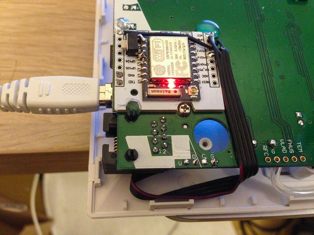
Instead of an oscilloscope, we solder and glue with a hot glue to the scarf with ESP8266:

We connect it via a UART to a computer (there are two wires in the photo, without earth, because the meter is powered by the same laptop) and we start writing code.

► Sources
The code is written in the Arduino environment with ESP8266 support enabled (how to enable it, you can read it here ). How to press a button for firmware, I think, will figure it out, or with the help esp8266.ru.
The project itself consists of three files: the project file, and the connected library, sponsored by fedorro , which in turn used the lessons from here .
Also, the code can be viewed on my GitHub . Pull requests are welcome, as well as tips in the comments on how you can do better!
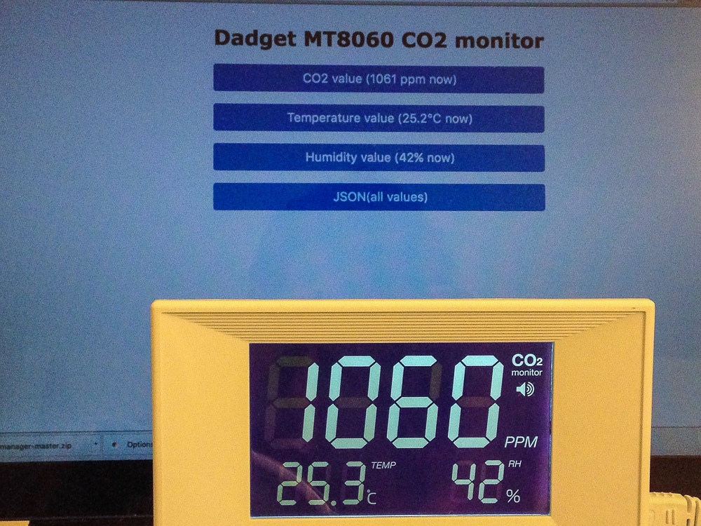
Run, go to the device page ...

Works! Put the wires in order, we find for the board free space in the case:
We fix it with a drop of hot melt, and now, the operation is completed, it remains tosew up the lid (not forgetting the tube), and install it in the right place at home:

However, so far the situations “looked at the meter screen” and “looked at the web page” are not very different. To make it more interesting, you need to either manage something, or collect statistics.
Of course, you can still dig deeper with ESP, using its memory for storing graphics, or making it control some WiFi relay ... But I'm not a fan of distributed systems, and I think that a smart home should have at least one server .
In order to make a single reading of the graph, I will use the possibilities of Logic Machine - scripts and trends. Of course, all the same can be done on any computer, but since I have the tools at hand, why not use it.
Create a new Sheduled script (scheduled), configure it to run every minute:

Inside we write something like this:
Voila! We received the first testimony:

Now we need to turn them into nice graphics. There is nothing easier (forgive me Dadget for the unscrupulous advertising of our controller, I am already finishing)! Trends logs -> Add new trend log log:

It now remains to wait a week or two to collect data, and here they are, our graphs:

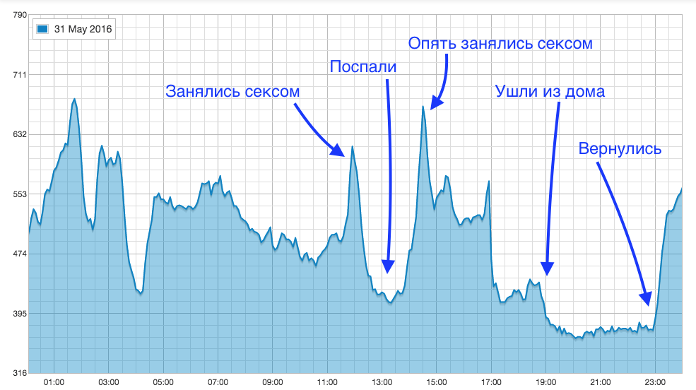
And of course, the most interesting schedule:

It turned out that it was very interesting to observe the level of CO₂ and draw parallels between the changes in the chart and your actions!
Fact number 1 : Gas stove VERY greatly increases the level of CO₂.
Fact # 2 : In the absence of people and at least a slightly open window (even in micro-ventilation mode), the level of CO₂ quickly drops to background values.

Fact # 3 : People in the apartment (even asleep) make a significant contribution to the amount of carbon dioxide. It is important to open the windows (it is possible in another part of the apartment) at night in order not to inflate to harmful values.
Fact # 4 : The amount of CO₂ released by a person is highly dependent on his activity. It is worth waking up and half-sleeping to walk around the apartment as the amount of carbon dioxide begins to grow.

Fact # 5 : The amount of CO₂ released by a human is VERY highly dependent on his activity. And the type of activity.
As a venue for testing CO -controlled ventilation, I chose an office . It is already configured to control the ventilation from the controller (how exactly, see the previous link), so I just had to adjust the response to raising CO₂. LM does this like this:
We create a new script of the Event-based type (executed when the object changes), set the object to which we are recording the current CO₂ value as the monitoring object:

In the script code, we write simple logic that will turn on ventilation at a carbon dioxide level above 1000ppm, and turn it off at a level less than 800, implementing hysteresis to prevent frequent on-off ventilation:
Thus, the ventilation will turn on when the CO level rises to 1000ppm, and does not turn off until it drops to 800ppm.
Buzzing!

References:
Similar device internals and protocol description
Instrument Overview
Parsing device
Connect Meter to Arduino
If you are interested in the topics of Internet devices and smart home, welcome to the channel in the telegraph: telegram.me/IOTandSmarthome
Within 14 days from the date of publication of this article, you can purchase the Air Quality Monitor with a 10% discount using the GEEKT-MK code.
And when, at one point, I thought about monitoring not only the temperature and humidity in my home, but also the amount of carbon dioxide, I immediately remembered this company and its devices.
As you know, there are two sensors in the Djadget - one is connected by wire to the computer, and the other can be connected to the controller (as was done here ) for reading the readings. I was more interested in the second version of the controller, since I wanted the sensor not to be tied to the computer with a wire, and it could be placed anywhere in the apartment.
')
So, it was decided: we take the monitor CO₂ and fasten WiFi to it in the form of ESP8266.
► WiFi Inside
The patient is ready for surgery:
For opening, you need to pull out 4 rubber plugs:
And unscrew the screws hiding under them. After that, you can carefully separate the two parts of the body (for example, a plastic card):
Caution - because inside they are connected by a tube, which must be carefully unhooked and tucked inside the case so as not to interfere:
At the bottom of the board there are 4 contact holes:
People familiar with electronics will spell their assignment next to it. The rest will understand this from my explanation: V (voltage) - power, D (data) - data, C (clock) - synchronization, G (ground) - ground.
G, also known as GND, also known as “ground,” is the zero point from which the supply voltage (that is, V) and the levels of the data signals are measured. In the philistine practice, we can say that G is a minus, and V is a plus, as in batteries. It will even be true ... until one more voltage appears, after which the conventions such as "minus" will fly to hell.
C, it's clock, it's clock, it's sync - a special signal that tells the receiving party when to read the signal from the data line (which is D).
In contrast to asynchronous protocols (such as UART / RS-232), where there is no such signal, and synchronization is based on the exact indication of the same frequency (= speed) on the transmitting and receiving side (all these 1200, 9600, 115200 baud), the synchronous protocol has a separate line, the level change on which means that the receiver should measure the state of the data line by understanding which bit is being transmitted at the current moment.
The advantage of the synchronous protocol is insensitivity to the difference in the clocking of devices (you can at least dial bytes with pens, if not time limits), the downside is the need for a separate wire. In principle, with the same transmission frequency, it is possible to disassemble synchronous transmission without a clock signal, but we will not suffer from such perversions.
We catch the oscilloscope on the contacts and see the data packages:
Approaching, and now we can see the individual bits:
We can even decrypt the message, but we will not. It is important for us to understand that he is really sending something, so that later he will not think “why my data does not come” because of their absence.
Instead of an oscilloscope, we solder and glue with a hot glue to the scarf with ESP8266:
We connect it via a UART to a computer (there are two wires in the photo, without earth, because the meter is powered by the same laptop) and we start writing code.
► Sources
The code is written in the Arduino environment with ESP8266 support enabled (how to enable it, you can read it here ). How to press a button for firmware, I think, will figure it out, or with the help esp8266.ru.The project itself consists of three files: the project file, and the connected library, sponsored by fedorro , which in turn used the lessons from here .
I will hide the code under the spoiler, not even embarrass immature minds
File first, CO2_meter.ino :
File second, mt8060_decoder.cpp :
File three, mt8060_decoder.h
#define PIN_CLOCK 14 // , "" — #define PIN_DATA 12 // , "D" — #include <ESP8266WiFi.h> #include <ESP8266WebServer.h> #include "mt8060_decoder.h" const char* ssid = "MikroTik-951"; // const char* password = "FAKEPASSWORD"; // String co2_value = ""; // ppm String tmp_value = ""; // String hum_value = ""; // int error_count = 0; // (, , ) ESP8266WebServer server(80); // void setup() { Serial.begin(115200); // UART WiFi.begin(ssid, password); // WiFi while (WiFi.status() != WL_CONNECTED) { delay(500); Serial.print("."); // UART, } Serial.println(""); Serial.print("WiFi connected, IP "); Serial.println(WiFi.localIP()); server.on("/co2", co2_show); // , server.on("/tmp", tmp_show); server.on("/hum", hum_show); server.on("/json", json_show); server.onNotFound(NotFound_show); // server.begin(); pinMode(PIN_CLOCK, INPUT); // pinMode(PIN_DATA, INPUT); // attachInterrupt(digitalPinToInterrupt(PIN_CLOCK), interrupt, FALLING); // } void interrupt() // { bool dataBit = (digitalRead(PIN_DATA) == HIGH); unsigned long ms = millis(); mt8060_message* message = mt8060_process(ms, dataBit); // , , , , . if (message) { // if (!message->checksumIsValid) // , { error_count++; } else // ... { switch (message->type) //... ... { case HUMIDITY: hum_value = String((double)message->value / 100, 0); // Serial.print("HUM:"); Serial.println(hum_value); // UART break; case TEMPERATURE: tmp_value = String((double)message->value / 16 - 273.15, 1); // Serial.print("TMP:"); // -! ! -> (. )(. ) Serial.println(tmp_value); // UART break; case CO2_PPM: co2_value = String(message->value, DEC); // CO₂ Serial.print("CO2:"); Serial.println(co2_value); // UART break; default: break; } } } } void co2_show() { //, CO₂ server.send(200, "text/plain", co2_value); } void tmp_show() { //, server.send(200, "text/plain", tmp_value); } void hum_show() { //, server.send(200, "text/plain", hum_value); } void NotFound_show() { //, String form = "<!DOCTYPE html><html lang=\"en\"><head><meta http-equiv=\"Content-Type\" content=\"text/html\"><meta name=\"viewport\" content=\"width=device-width, initial-scale=1, user-scalable=no\"><title>Dadget 8060 CO₂ monitor</title><style>.c{text-align: center;} div,input{padding:5px;font-size:1em;} input{width:95%;} body{text-align: center;font-family:verdana;} button{border:0;border-radius:0.3rem;background-color:#1fa3ec;color:#fff;line-height:2.4rem;font-size:1.2rem;width:100%;} .q{float: right;width: 64px;text-align: right;}</style><style type=\"text/css\"></style></head><body><div style=\"text-align:left;display:inline-block;min-width:260px;\"><h1>Dadget 8060 CO₂ monitor</h1><form action=\"/co2\" method=\"get\"><button>CO₂ value ([co2] ppm now)</button></form><br><form action=\"/tmp\" method=\"get\"><button>Temperature value ([tmp]° now)</button></form><br><form action=\"/hum\" method=\"get\"><button>Humidity value ([hum]% now)</button></form><br><form action=\"/json\" method=\"post\"><button>JSON(all values)</button></form></div></body></html>"; form.replace("[co2]", co2_value); // form.replace("[hum]", hum_value); form.replace("[tmp]", tmp_value); server.send(200, "text/html", form); // } void json_show() { //, JSON String json = "[{\"co2\":"; // c JSON json += co2_value; json += ",\"tmp\":"; json += tmp_value; json += ",\"hum\":"; json += hum_value; json += ",\"serial\":"; json += ESP.getChipId(); json += ",\"errors\":"; json += error_count; json += ",\"uptime_min\":"; json += String(millis()/60000); json += "}]"; server.send(200, "application/json", json); // } void loop() { server.handleClient(); // HTTP } File second, mt8060_decoder.cpp :
// Based on https://github.com/fe-c/MT8060-data-read code // All rights for reading code owned https://geektimes.ru/users/fedorro/ // and https://github.com/revspace #include "mt8060_decoder.h" #define MT8060_MAX_MS 2 // , #define MT8060_MSG_LEN 5 // 5 #define MT8060_MSG_TYPE_BYTE_IDX 0 #define MT8060_MSG_VAL_HIGH_BYTE_IDX 1 #define MT8060_MSG_VAL_LOW_BYTE_IDX 2 #define MT8060_MSG_CHECKSUM_BYTE_IDX 3 #define MT8060_MSG_CR_BYTE_IDX 4 #define BITS_IN_BYTE 8 static uint8_t buffer[MT8060_MSG_LEN]; // static int num_bits = 0; static unsigned long prev_ms; static mt8060_message _msg; static mt8060_message *msg = &_msg; void mt8060_decode(void) // { uint8_t checksum = buffer[MT8060_MSG_TYPE_BYTE_IDX] + buffer[MT8060_MSG_VAL_HIGH_BYTE_IDX] + buffer[MT8060_MSG_VAL_LOW_BYTE_IDX]; // msg->checksumIsValid = (checksum == buffer[MT8060_MSG_CHECKSUM_BYTE_IDX] && buffer[MT8060_MSG_CR_BYTE_IDX] == 0xD); // if (!msg->checksumIsValid) { return; } msg->type = (dataType)buffer[MT8060_MSG_TYPE_BYTE_IDX]; // msg->value = buffer[MT8060_MSG_VAL_HIGH_BYTE_IDX] << BITS_IN_BYTE | buffer[MT8060_MSG_VAL_LOW_BYTE_IDX]; // } // , , mt8060_message* mt8060_process(unsigned long ms, bool data) { if ((ms - prev_ms) > MT8060_MAX_MS) { num_bits = 0; } prev_ms = ms; if (num_bits < MT8060_MSG_LEN * BITS_IN_BYTE) { int idx = num_bits / BITS_IN_BYTE; buffer[idx] = (buffer[idx] << 1) | (data ? 1 : 0); num_bits++; if (num_bits == MT8060_MSG_LEN * BITS_IN_BYTE) { mt8060_decode(); // return msg; // } } return nullptr; // , } File three, mt8060_decoder.h
// Based on https://github.com/fe-c/MT8060-data-read code // All rights for reading code owned https://geektimes.ru/users/fedorro/ // and https://github.com/revspace #include <stdint.h> #include <stdbool.h> typedef enum { HUMIDITY = 0x41, TEMPERATURE = 0x42, CO2_PPM = 0x50, } dataType; typedef struct { dataType type; uint16_t value; bool checksumIsValid; } mt8060_message; mt8060_message* mt8060_process(unsigned long ms, bool data); Also, the code can be viewed on my GitHub . Pull requests are welcome, as well as tips in the comments on how you can do better!
Run, go to the device page ...
Works! Put the wires in order, we find for the board free space in the case:
We fix it with a drop of hot melt, and now, the operation is completed, it remains to
► Collect statistics
However, so far the situations “looked at the meter screen” and “looked at the web page” are not very different. To make it more interesting, you need to either manage something, or collect statistics.
Of course, you can still dig deeper with ESP, using its memory for storing graphics, or making it control some WiFi relay ... But I'm not a fan of distributed systems, and I think that a smart home should have at least one server .
In order to make a single reading of the graph, I will use the possibilities of Logic Machine - scripts and trends. Of course, all the same can be done on any computer, but since I have the tools at hand, why not use it.
Create a new Sheduled script (scheduled), configure it to run every minute:
Inside we write something like this:
local http = require('http') local json = require('json') local raw_data, code = socket.http.request('http://co2meter.lc/json') -- . DNS- if (code == 200) then -- 200.. local data = json.decode(raw_data) -- json lua if (data ~= nil) then -- json-... if (data[1].uptime_min > 2) then -- ( "" ) grp.update('S_CO2_CO2', data[1].co2) -- CO₂, grp.update('S_CO2_TMP', data[1].tmp) grp.update('S_CO2_HUM', data[1].hum) end end end Voila! We received the first testimony:
Now we need to turn them into nice graphics. There is nothing easier (forgive me Dadget for the unscrupulous advertising of our controller, I am already finishing)! Trends logs -> Add new trend log log:
It now remains to wait a week or two to collect data, and here they are, our graphs:
And of course, the most interesting schedule:
It turned out that it was very interesting to observe the level of CO₂ and draw parallels between the changes in the chart and your actions!
Fact number 1 : Gas stove VERY greatly increases the level of CO₂.
Fact # 2 : In the absence of people and at least a slightly open window (even in micro-ventilation mode), the level of CO₂ quickly drops to background values.
Fact # 3 : People in the apartment (even asleep) make a significant contribution to the amount of carbon dioxide. It is important to open the windows (it is possible in another part of the apartment) at night in order not to inflate to harmful values.
Fact # 4 : The amount of CO₂ released by a person is highly dependent on his activity. It is worth waking up and half-sleeping to walk around the apartment as the amount of carbon dioxide begins to grow.
Fact # 5 : The amount of CO₂ released by a human is VERY highly dependent on his activity. And the type of activity.
► Fan control
As a venue for testing CO -controlled ventilation, I chose an office . It is already configured to control the ventilation from the controller (how exactly, see the previous link), so I just had to adjust the response to raising CO₂. LM does this like this:
We create a new script of the Event-based type (executed when the object changes), set the object to which we are recording the current CO₂ value as the monitoring object:
In the script code, we write simple logic that will turn on ventilation at a carbon dioxide level above 1000ppm, and turn it off at a level less than 800, implementing hysteresis to prevent frequent on-off ventilation:
-- value = grp.getvalue("S_CO2_CO2") -- if (value > 1000) then -- , 1000ppm... grp.write('HP-7.1', true) --.. elseif (value < 800) then -- CO₂ , 800ppm... grp.write('HP-7.1', false) --.. end Thus, the ventilation will turn on when the CO level rises to 1000ppm, and does not turn off until it drops to 800ppm.
Buzzing!
References:
Similar device internals and protocol description
Instrument Overview
Parsing device
Connect Meter to Arduino
If you are interested in the topics of Internet devices and smart home, welcome to the channel in the telegraph: telegram.me/IOTandSmarthome
Within 14 days from the date of publication of this article, you can purchase the Air Quality Monitor with a 10% discount using the GEEKT-MK code.
Source: https://habr.com/ru/post/394333/
All Articles