RS232 3-in-1 device for a home Linux server: Part 1 (Hardware)
- Part 1 (Hardware)
- Part 2 (Server)
Servers assembled from components not specifically designed for this usually have two drawbacks. They lack a hardware watchdog timer and often lack entropy for a number of services. The lack of entropy is especially relevant for not heavily loaded servers. This is due to the fact that the Linux kernel uses system activity as the source of entropy, namely: network equipment, disk subsystem and hardware interrupts.
Also in the home server it is often necessary to have a more economical, in comparison with Wi-Fi, radio module for communication with autonomous sensors.
There is a large selection of devices with which you can solve any of these problems, but connecting each of them requires a separate port. Assessing the situation, I finally decided to develop a 3-in-1 device connected to the RS232 (COM) port. The remaining requirements were as follows:
- Hardware watchdog timer, suitable for working with the standard
watchdog; - True random number generator based on the reverse avalanche breakdown effect of the pn junction;
- Radio module nRF24L01 + for data collection from autonomous sensors.
Thus, the device received the name WRN from the names of its constituent subsystems: WDT (WatchDog Timer), RNG (Random Number Generator), nRF24L01 +.
Running a lot ahead, I want to note that the lack of entropy can be easily eliminated without additional devices, by running the rngd daemon with the key --rng-device=/dev/urandom . The /dev/urandom operation algorithms are good enough for this, but I wanted a hardware RNG, so there was nowhere to go, I had to do it.
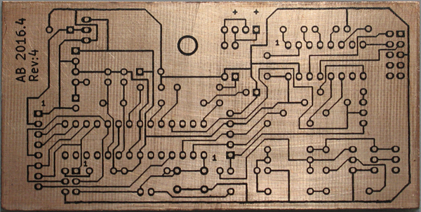
Schematic diagram
(click to enlarge)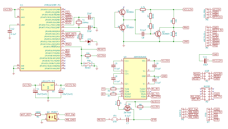
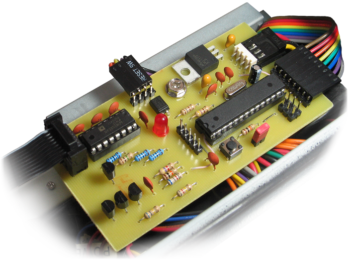
The device is based on the ATmega328P microcontroller and operates at a maximum frequency of 20MHz. For the sake of experiment, I tried to overclock, but I couldn't find a crystal more modest than 32MHz, the microcontroller did not work with it. Nevertheless, any quartz resonator can be used in the device in reasonable, from the point of view of the microcontroller, limits. The article will have more details about this, but in fact, it suffices to calculate the constants for the software clock and build the loader with the appropriate parameters.
The diagram provides connectors for connecting the SPI programmer and USB-UART converter, which is required for debugging, as it is not easy to get direct access to the RS232. In some places the scheme is not optimal, since it was assembled from components that were available. If desired, it can be optimized, the sources for KiCAD are available on the GitHub alexcustos / wrn-project in the pcb directory.
- C12 - protection against interference required when using an analog-to-digital converter;
- Y1, C3, C4 - standard connection of the quartz resonator;
- D1, R11 - LED and resistor limiting current in its circuit, chosen empirically, because the LED could not be identified;
- PB1, R2 - the RESET button and pull-up (pull-up) of the output to a high level in order to avoid triggering as a result of induced interference;
- U1, C1, C2 - voltage regulator for the radio module and smoothing filters, the 800mA regulator is of course not needed here, 100mA is more than enough;
- U2, R1 - optocoupler and a resistor that limits the current to 20mA in the LED circuit;
- U3, C5, C6, C9, C10 - RS232-TTL level converter and standard piping;
- P3, C11 - power supply +5 and + 12V from the FDD connector and a smoothing filter for 12V;
- P4 - connector for a radio module;
- P1 - ISP connector for downloading the code to the microcontroller, required for firmware loader;
- P2 - connector for connecting to computer RS232 port;
- P5 - contact pad for connecting a controlled RESET button and a backup button from the front panel of the case;
- P7 - connector for USB-UART converter connection.
RS232-TTL Level Converter
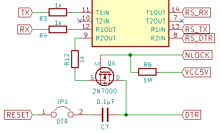
Here, the ADM202EANZ chip from Analog Devices is used just because I have three copies of the MAX232ACPE not working properly. Otherwise, these chips are completely interchangeable and you can use the more common version of Maxim.
Resistors R3, R4, R12 are needed to connect to the USB-UART converter circuit. At different levels on two competing signal lines, the resistance will act as a voltage divider. Since the load impedance is much less than 1kΩ, the signal from the directly connected converter will only be slightly attenuated, and the signal from U3 can be completely neglected.
It is not convenient to use only SPI for flashing the device, since a programmer and direct access to the device is required. In addition, there is a radio module on the SPI lines, which would also have to be connected via resistors.
Firmware through the bootloader is a good option, but also has a drawback. The loader perceives the DTR (Data Terminal Ready) signal as a reboot command, which leads to an undesirable device reboot when the terminal is connected.
It is not difficult to fight this; it is enough to add a Q4 field-effect transistor as a switch and block the DTR line immediately after the standard load. If you need to flash the device, just send the unlock command. Resistor R6 is needed for the line to be connected by default; capacitor C7 - for reliable operation RESET.
The ability to flash a device can be a serious vulnerability for the entire system, so you need the hardware ability to block the firmware, for this it is enough to open the jumper JP1 . In addition, it is useful for debugging when a USB-UART converter is connected.
Noise generator based on avalanche breakdown effect of pn junction

The generator here is a reverse biased pn junction of the Q1 transistor. According to the passport Vebo = 6V, this is the maximum reverse-turn-on voltage when the collector is open (not connected). Of course, the transistor will not exit from the operating mode immediately when this threshold is exceeded, so for reliability, you need to increase the voltage to 12V. In this mode, in the pn junction, impact ionization will occur in those places where the electric field strength is sufficient. This process is extremely unstable, the constant failure and the occurrence of ionization in various places of the pn junction, leads to a random change in current. The transistor is used here only because the reverse bias voltage of the diodes is much higher, for example, the popular 1N4148 is 100V.
The rest of the circuit works as follows: Q2 amplifies the current from Q1 ; R5 limits the current in the collector-emitter circuit Q2 ; C8 cuts off the constant component of the signal from Q2 , aligning the spectrum somewhat; ( R7 + R8 ) provides current to the base-emitter circuit Q3 as a constant additive to the current from C8 ; Q3 amplifies the total current from C8 and ( R7 + R8 ); R9, R10 divider, limits the voltage to 5V at the input of the microcontroller.
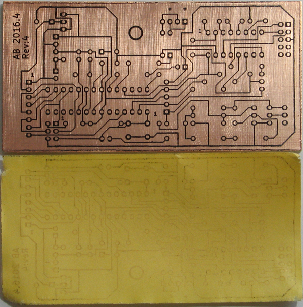
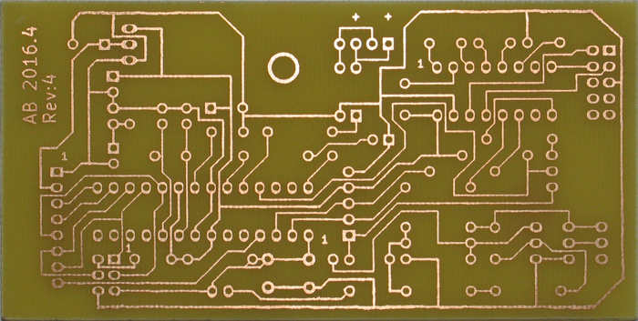
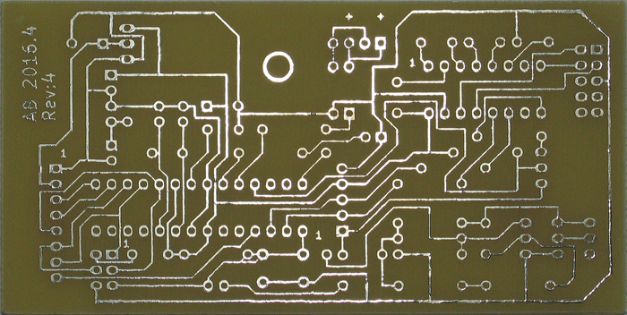
Printed circuit board
In the previous article, there was already an instruction on how to draw a circuit and dilute the board in KiCAD. There are no fundamental differences, only the board now needs to be printed.
The dimensions of the printed circuit board are usually determined after layout, but you can set them initially and adjust them as necessary. This work is done on the Edge.Cuts layer with the tool  or other suitable, if you need a round board or with rounded edges.
Before printing, it is desirable to bring the pads in order. The fact is that the shape of the pad and the diameter of the holes for each element are different. Accordingly, unnecessary difficulties may arise when drilling, soldering, or even during tracing, when the tracks will not go where they should be.
This process is not very convenient, because in the pcbnew editor macros are still in development, and the hot key is assigned only to edit the pad. However, this is not difficult. First you need to determine the diameter of the drill, in most cases the optimum will be 1mm, and assign the appropriate hole to all sites. Then, if necessary, correct the shape of the pads so that there is enough copper on them, but at the same time they are quite far from each other and from the tracks.
To edit a separate pad ( Pad ), you need to point at it with the cursor and press E, or right-click on it  then
then  . To copy the settings of the newly edited site to the current one, you need to use
  , and to apply the settings to the group, select
  . The latter option somewhat simplifies the process, but is applicable only to one footprint or a group of identical. Here you also need to pay attention to the checkboxes of the filter, which limit the scope.
Perform design rules check tool is provided for checking the PCB.  → Start DRC, both the Problems / Markers and Unconnected tabs must be empty.
In conclusion, you must visually make sure that everything is in order. To do this, be sure to admire the result in View → 3D Viewer . Then export the PCB to Gerber format (something like PDF for documents) File → Plot → Gerber (Plot format), here select the necessary layers, in this case: B.Cu , Edge.Cuts and click Plot , then get the file with holes Generate Drill File → Drill File , and close both windows.
KiCAD has a built-in GerbView viewer.  , you can use it or any friend. If everything is in order, it remains to select the menu item File → Print to print the board. Here, select the B.Cu layer, uncheck Print frame ref and select the size of the labels for the holes. With full-sized holes, Real drill will need to use an awl to mark the center so that the drill does not slide off, and with the small mark Small mark you have to drill solder (after tinning) and copper. If the drill is good, the last option is probably preferable.
- The first revision is Real drill without coreing, a good Dremel 0.8mm drill, blunted about 3/4, finished with a drill 1.0, the result is bad: the holes started in a random place of a circle, some of the pads were torn, the DIP panels were installed with difficulty;
- second revision - Real drill with core, the previous one was reduced to 1.0, it drilled out the entire charge to them, the result is good;
- the third revision - Small mark , drills from an incomprehensible set, the previous 1.0 blunted immediately, then two more for 1.0 and one 0.9, finished with a drill 1.1, the result is good;
- the fourth revision is Real drill with core, drills from another incomprehensible set, 3 drills 1.0 blunted, the result is good, the photo can be viewed below under the spoiler.
Now it remains to embody the idea in the "iron". This process is fascinating, but a lot has been written about it. Therefore, the photo of the process with its subjective comments hid under the spoiler. Speech, of course, on LUT.
First, the board should be degreased with acetone or alcohol and clean it with fine sandpaper along and across. It is desirable to print the drawing on thermal transfer paper.
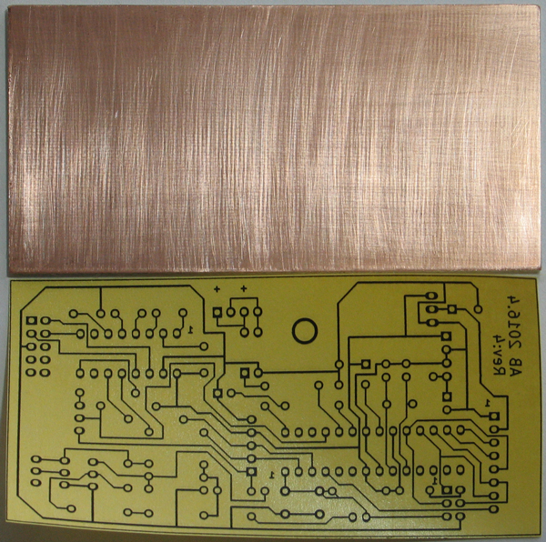
It is necessary to transfer the iron heated up to 180 ° C (three points), usually it is the maximum. When you touch the iron paper sticks immediately and securely, therefore, holding it enough to stroke with one edge, then boldly over the entire area. When the smell of burnt paper appears, the process can be stopped; three to five minutes are enough. Then let the fiberglass cool and peel off the paper.
The boundaries of the printed circuit board, it is desirable to erase, because copper is not needed there. Acetone is well suited for this, toner is removed in one motion, the main thing is not to hook the tracks.
The most convenient recipe for copper etching solution:
- 100 ml of water;
- 6 tablets of hydroperit;
- 50 g of citric acid;
- 20 g (two teaspoons) of salt.
Water and hydroponic are equivalent to 100 ml of 3% hydrogen peroxide, but the peroxide has a specific odor, therefore it is better to use hydroponite.
The solution must be prepared in a special dish, which is subsequently not allowed to be used for storage and cooking. It is better to use glass, but the rules are simple: no metal and easy to clean. You also need to remember about safety, so that the solution does not get on the skin, eyes, and especially inside.
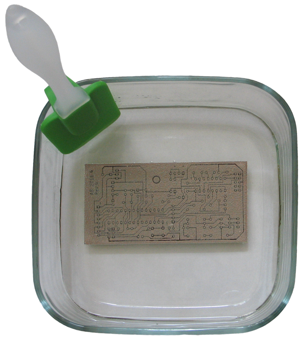
The process proceeds without odor and special effects. On the surface of the board bubbles are formed which must be disposed of. In this case, by shifting the board from the solution, and then back when the bubbles collapse. It was probably not necessary to heat the solution at 30 ° C in the room, but I conducted the first experiments at 23 ° C, which was clearly not enough. Therefore, this time I also put the tank in a basin with hot tap water.
Bubbles are formed intensively, so you can roll the board without leaving at all, but it’s quite enough once every 2-3 minutes. The process must be interrupted when it is obvious that there is no longer any copper. It usually takes 40-50 minutes. If the solution has not yet fully worked, bubbles will form as the copper from the side of the toner remains available.

The spent solution can be poured into domestic sewage. Toner is easily washed off with acetone.
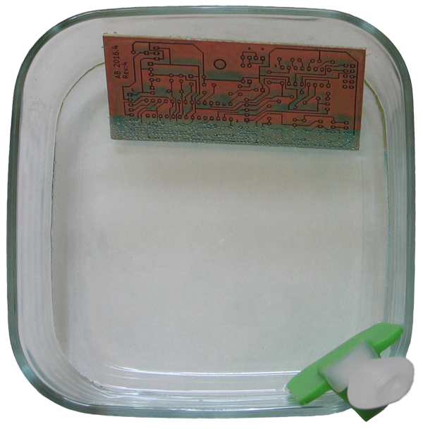
Now the board needs to be tinned to eliminate possible small cracks and prevent copper oxidation. The easiest way to do this is to alloy Rose. To do this, you will need enamelware (will become unsuitable for cooking and storing food), some water to cover the board by about 5 mm, a small spoonful of citric acid in water (to remove oxides from copper) and two or three drops of Rosa alloy. Now you need to heat it all up to a boil, while the Rosa alloy will melt and it can be easily poured onto the board and applied to the tracks with a rubber spatula. When the alloy is on all tracks, it remains only to remove the excess, sliding them beyond the board. From three drops usually one remains in the size one and a half to two initial, it can be reused.
By the way, the dishes should not be aluminum, since citric acid dissolves aluminum oxide, which causes aluminum to actively oxidize, as a result, a lot of garbage and zero visibility are formed in the container.
It is desirable to drill under a thin layer of water so that the drill does not overheat, and then it will be easier to clean.
(click to enlarge)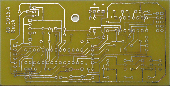
The result was the following product:
(click to enlarge)

Software
The project was developed in C ++ in AtmelStudio, all source codes are available on the GitHub alexcustos / wrn-project in the wrn directory. Part of the code was borrowed from the Arduino IDE repository and modified to remove all unnecessary and unlink the code from the Arduino core. For the same purpose, two libraries have been changed, which are necessary for working with a radio module. Their source code is also available on GitHub as separate projects:
The code contains data processing from the sensor, which can be found at the link: ATtiny85: prototype of a wireless sensor .
Loader
To program the device through the serial port, you need a bootloader. Optiboot is a great option, suitable for Atmel AVR microcontrollers. It is easy to assemble it with the required parameters, namely, set the clock frequency and data transfer rate for the serial port, and most importantly, specify the port on which it will flash with a LED.
To flash the bootloader, the device, with the radio module disconnected, needs to be connected via SPI to the programmer. Then compile and flash your own version of the bootloader, or use the ready-made version just below.
To compile, you will need a set of programs that can be installed in Ubuntu with the command:
sudo apt-get install git gcc-avr binutils-avr gdb-avr avr-libc avrdude Then run:
git clone https://github.com/Optiboot/optiboot.git cd optiboot/optiboot/bootloaders/optiboot make atmega328_isp AVR_FREQ=20000000L BAUD_RATE=115200 LED=C0 EFUSE=FD HFUSE=DE LFUSE=F7 ISPTOOL=stk500v1 ISPPORT=/dev/ttyACM0 You should pay attention to the output of the last command to make sure that the bootloader was successfully assembled and flashed. Also closer to the beginning will be the line:
BAUD RATE CHECK: Desired: 115200, Real: 113636, UBRRL = 21, Error=-1.3% It makes sense to save the Real value, the fact is that the firmware process via USB-UART only worked for me at this speed, and through RS232-TTL only on the standard one. Reducing Error to 0.0% does not make sense, since an error of 1-2 percent should not cause problems, but I tried it - it did not help.
The microcontroller with a clock frequency of 20MHz can work with BAUD_RATE to 250000. The speed had to be reduced due to the RS232-TTL converter, even the ADM202EANZ with the declared speed of 230,000, without errors, it works only on 57600. At a speed of 115200 it appears about once an hour bad byte. For firmware, this is not critical, since avrdude checks everything that it writes, and you can always try again.
FUSEs:
- EFUSE = FD - reboot when trying to write to the EEPROM when the power supply voltage is below 2.7V, you can specify FC (4.3V), but if you debug a device with USB power, then 2.7V is more reliable.
- HFUSE = DE - 512 byte downloader, programming via SPI is allowed;
- LFUSE = F7 - external full-swing crystal oscillator with standard delays, differs from the others in that the microcontroller will not reduce the voltage at the output of XTAL2.
In the settings of the programmer (ISPTOOL, ISPPORT), arduino is indicated as a programmer, which is a good option if something like that gathers dust.
The bootloader prepared according to the scheme proposed above can be downloaded at the link: optiboot_atmega328p_20MHz.hex . For its firmware, it is enough to install only avrdude and execute the command:
avrdude -C/etc/avrdude.conf -v -patmega328p -cstk500v1 -P/dev/ttyACM0 -b19200 \ -e -Ulock:w:0x3F:m -Uefuse:w:0xFD:m -Uhfuse:w:0xDE:m -Ulfuse:w:0xF7:m \ -Uflash:w:"optiboot_atmega328p_20MHz.hex":i -Ulock:w:0x2F:m The first line defines the microcontroller and programmer, followed by the commands run sequentially: chip cleaning, unlocking the bootloader area, flashing FUSEs, booting the firmware, and locking the recording to the bootloader area.
If everything went well, the LED will flash three times a second, indicating that everything is OK with the Optiboot, but the firmware is not yet loaded.
Firmware
In general, the code came out quite a lot, but I hope to deal with it will not be difficult. Below is a list of features that are worth paying attention to.
The initialization code of the SPI and serial port requires the definition of F_CPU. It is better to add it in the compiler options or by directly specifying the -DF_CPU=20000000L switch. Software clocks also use this definition, but the constants are hard-coded there and require manual recalculation when changing F_CPU.
The main () function traditionally contains initialization and an infinite loop in which work with the device is performed:
- reset the watchdog timer of the microcontroller;
- receiving data from the radio module;
- work with noise generator;
- work with the system watchdog timer;
- read commands from the serial port;
- command processing and sending data via the serial port.
[C|W|R|N][0-99]:[1]:[2] , , , — , . .
(struct) . , , . , . , -fpack-struct , AtmelStudio .
, , , . , . , — .
. , . , .
, EEPROM . .
(uptime). uptime . .
- , , , . uint16_t (~12.5 ).
8 . RF24/RF24Network, . , 1000 , 64 : 20000000 () / 256 (8 ) / 64 () ~= 1220 , 256 * 64 * 1000 / 20000000 = 8192/10000 = 512/625 . TIMER0_OVF :
m += MILLIS_INC; // = 0, , () f += FRACT_INC; // = 512, if (f >= FRACT_MAX) { // = 625, f -= FRACT_MAX; // m += 1; } , , , .
, pn , pn - . . , .
, , .
, , , , , , , .
measure = read_measure(); // 8 10 ( ) num_measures++; // ( ) // measure_limit > 0 if (num_measures == measure_limit) { balance = false; // if (pan_left > pan_right) fault = pan_left - pan_right; else fault = pan_right — pan_left; // measure_limit, acceptable_fault = ((measure_limit - 1) / 256 + 1) * 3; if (fault > acceptable_fault) { // , // , , if (pan_right > pan_left && threshold < uint8_t(-1)) threshold++; else if (pan_left >= pan_right && threshold > 0) threshold--; } else balance = true; ... // pan_left, pan_right, num_measures ( ) ... // ( ) if (balance && measure_limit) { // measure_limit = 0; // , return false; // , } } else { // , if (measure <= threshold) pan_left++; else pan_right++; } :
byte <<= 1; // , num_measures % 8 == 0 if (measure > threshold) byte |= 0b00000001; rngtest rngd monobit . , , ADC «», . , :
byte ^= bit_flip; // XOR bit_flip = !bit_flip; , , monobit . . 636 / dieharder . - 500MB. , . /dev/urandom . dieharder .
rngtest: bits received from input: 4195417088
rngtest: FIPS 140-2 successes: 209549
rngtest: FIPS 140-2 failures: 221
rngtest: FIPS 140-2(2001-10-10) Monobit: 21
rngtest: FIPS 140-2(2001-10-10) Poker: 70
rngtest: FIPS 140-2(2001-10-10) Runs: 59
rngtest: FIPS 140-2(2001-10-10) Long run: 72
rngtest: FIPS 140-2(2001-10-10) Continuous run: 0
rngtest: bits received from input: 4181721088
rngtest: FIPS 140-2 successes: 208937
rngtest: FIPS 140-2 failures: 149
rngtest: FIPS 140-2(2001-10-10) Monobit: 20
rngtest: FIPS 140-2(2001-10-10) Poker: 21
rngtest: FIPS 140-2(2001-10-10) Runs: 57
rngtest: FIPS 140-2(2001-10-10) Long run: 52
rngtest: FIPS 140-2(2001-10-10) Continuous run: 0
#=============================================================================#
# dieharder version 3.31.1 Copyright 2003 Robert G. Brown #
#=============================================================================#
   rng_name |rands/second| Seed |
stdin_input_raw| 1.99e+07 | 871678203|
#=============================================================================#
             test_name |ntup| tsamples |psamples| p-value |Assessment
#=============================================================================#
  0: diehard_birthdays| 0| 100| 100|0.23013568| PASSED
  1: diehard_operm5| 0| 1000000| 100|0.41464749| PASSED
  3: diehard_rank_6x8| 0| 100000| 100|0.83194246| PASSED
  4: diehard_bitstream| 0| 2097152| 100|0.98469009| PASSED
  7: diehard_dna| 0| 2097152| 100|0.82184561| PASSED
  8: diehard_count_1s_str| 0| 256000| 100|0.63516902| PASSED
 10: diehard_parking_lot| 0| 12000| 100|0.15579947| PASSED
 11: diehard_2dsphere| 2| 8000| 100|0.94799044| PASSED
 12: diehard_3dsphere| 3| 4000| 100|0.16755480| PASSED
 14: diehard_sums| 0| 100| 100|0.00420819| WEAK
 15: diehard_runs| 0| 100000| 100|0.58812798| PASSED
 15: diehard_runs| 0| 100000| 100|0.23381862| PASSED
100: sts_monobit| 1| 100000| 100|0.11747720| PASSED
101: sts_runs| 2| 100000| 100|0.12598371| PASSED
102: sts_serial| 1| 100000| 100|0.11747720| PASSED
102: sts_serial| 2| 100000| 100|0.98806196| PASSED
102: sts_serial| 3| 100000| 100|0.93420112| PASSED
102: sts_serial| 3| 100000| 100|0.88625906| PASSED
102: sts_serial| 4| 100000| 100|0.81837353| PASSED
102: sts_serial| 4| 100000| 100|0.44680983| PASSED
102: sts_serial| 5| 100000| 100|0.30069422| PASSED
102: sts_serial| 5| 100000| 100|0.59918415| PASSED
102: sts_serial| 6| 100000| 100|0.94111872| PASSED
102: sts_serial| 6| 100000| 100|0.97775411| PASSED
102: sts_serial| 7| 100000| 100|0.71034876| PASSED
102: sts_serial| 7| 100000| 100|0.37205549| PASSED
102: sts_serial| 8| 100000| 100|0.62281679| PASSED
102: sts_serial| 8| 100000| 100|0.61865217| PASSED
102: sts_serial| 9| 100000| 100|0.12357283| PASSED
102: sts_serial| 9| 100000| 100|0.62028539| PASSED
102: sts_serial| 10| 100000| 100|0.70302730| PASSED
102: sts_serial| 10| 100000| 100|0.36150774| PASSED
102: sts_serial| 11| 100000| 100|0.02416524| PASSED
102: sts_serial| 11| 100000| 100|0.00210157| WEAK
102: sts_serial| 12| 100000| 100|0.15545193| PASSED
102: sts_serial| 12| 100000| 100|0.25167693| PASSED
102: sts_serial| 13| 100000| 100|0.19659046| PASSED
102: sts_serial| 13| 100000| 100|0.56538654| PASSED
102: sts_serial| 14| 100000| 100|0.15529368| PASSED
102: sts_serial| 14| 100000| 100|0.99005364| PASSED
102: sts_serial| 15| 100000| 100|0.15517199| PASSED
102: sts_serial| 15| 100000| 100|0.91135159| PASSED
102: sts_serial| 16| 100000| 100|0.70484328| PASSED
102: sts_serial| 16| 100000| 100|0.71149544| PASSED
201: rgb_minimum_distance| 0| 10000| 1000|0.00000000| FAILED
202: rgb_permutations| 5| 100000| 100|0.72724154| PASSED
203: rgb_lagged_sum| 0| 1000000| 100|0.79186771| PASSED
204: rgb_kstest_test| 0| 10000| 1000|0.46365770| PASSED
206: dab_dct| 256| 50000| 1|0.53224869| PASSED
207: dab_filltree| 32| 15000000| 1|0.87205525| PASSED
207: dab_filltree| 32| 15000000| 1|0.28341671| PASSED
208: dab_filltree2| 0| 5000000| 1|0.69766563| PASSED
208: dab_filltree2| 1| 5000000| 1|0.68877816| PASSED
209: dab_monobit2| 12| 65000000| 1|0.99154840| PASSED
#=============================================================================#
# dieharder version 3.31.1 Copyright 2003 Robert G. Brown #
#=============================================================================#
   rng_name |rands/second| Seed |
stdin_input_raw| 2.09e+07 |2043744116|
#=============================================================================#
             test_name |ntup| tsamples |psamples| p-value |Assessment
#=============================================================================#
  0: diehard_birthdays| 0| 100| 100|0.04140546| PASSED
  1: diehard_operm5| 0| 1000000| 100|0.37860771| PASSED
  3: diehard_rank_6x8| 0| 100000| 100|0.51810908| PASSED
  4: diehard_bitstream| 0| 2097152| 100|0.87265669| PASSED
  7: diehard_dna| 0| 2097152| 100|0.28188785| PASSED
  8: diehard_count_1s_str| 0| 256000| 100|0.01571303| PASSED
 10: diehard_parking_lot| 0| 12000| 100|0.27155245| PASSED
 11: diehard_2dsphere| 2| 8000| 100|0.56675436| PASSED
 12: diehard_3dsphere| 3| 4000| 100|0.95480977| PASSED
 14: diehard_sums| 0| 100| 100|0.00076186| WEAK
 15: diehard_runs| 0| 100000| 100|0.62119123| PASSED
 15: diehard_runs| 0| 100000| 100|0.79241488| PASSED
100: sts_monobit| 1| 100000| 100|0.76618520| PASSED
101: sts_runs| 2| 100000| 100|0.89128426| PASSED
102: sts_serial| 1| 100000| 100|0.76618520| PASSED
102: sts_serial| 2| 100000| 100|0.51804588| PASSED
102: sts_serial| 3| 100000| 100|0.54076681| PASSED
102: sts_serial| 3| 100000| 100|0.51414389| PASSED
102: sts_serial| 4| 100000| 100|0.18600760| PASSED
102: sts_serial| 4| 100000| 100|0.22984905| PASSED
102: sts_serial| 5| 100000| 100|0.25883020| PASSED
102: sts_serial| 5| 100000| 100|0.99315299| PASSED
102: sts_serial| 6| 100000| 100|0.40048642| PASSED
102: sts_serial| 6| 100000| 100|0.73022511| PASSED
102: sts_serial| 7| 100000| 100|0.79035813| PASSED
102: sts_serial| 7| 100000| 100|0.91930371| PASSED
102: sts_serial| 8| 100000| 100|0.51635740| PASSED
102: sts_serial| 8| 100000| 100|0.87010763| PASSED
102: sts_serial| 9| 100000| 100|0.95493347| PASSED
102: sts_serial| 9| 100000| 100|0.15935465| PASSED
102: sts_serial| 10| 100000| 100|0.32276697| PASSED
102: sts_serial| 10| 100000| 100|0.67645664| PASSED
102: sts_serial| 11| 100000| 100|0.64714937| PASSED
102: sts_serial| 11| 100000| 100|0.83931114| PASSED
102: sts_serial| 12| 100000| 100|0.98898429| PASSED
102: sts_serial| 12| 100000| 100|0.98306183| PASSED
102: sts_serial| 13| 100000| 100|0.73353342| PASSED
102: sts_serial| 13| 100000| 100|0.75717141| PASSED
102: sts_serial| 14| 100000| 100|0.18283051| PASSED
102: sts_serial| 14| 100000| 100|0.52874060| PASSED
102: sts_serial| 15| 100000| 100|0.35740156| PASSED
102: sts_serial| 15| 100000| 100|0.83391413| PASSED
102: sts_serial| 16| 100000| 100|0.61391208| PASSED
102: sts_serial| 16| 100000| 100|0.83537094| PASSED
201: rgb_minimum_distance| 0| 10000| 1000|0.00000000| FAILED
202: rgb_permutations| 5| 100000| 100|0.85828591| PASSED
203: rgb_lagged_sum| 0| 1000000| 100|0.84986413| PASSED
204: rgb_kstest_test| 0| 10000| 1000|0.25942548| PASSED
206: dab_dct| 256| 50000| 1|0.62442278| PASSED
207: dab_filltree| 32| 15000000| 1|0.39920277| PASSED
207: dab_filltree| 32| 15000000| 1|0.57982406| PASSED
208: dab_filltree2| 0| 5000000| 1|0.90094772| PASSED
208: dab_filltree2| 1| 5000000| 1|0.58950861| PASSED
209: dab_monobit2| 12| 65000000| 1|0.94848945| PASSED
201 - , . :
cat /dev/urandom | dieharder -g 200 -d 201 , :
cat /dev/urandom | dieharder -g 200 -a :
rgb_minimum_distance| 2| 10000| 1000|0.20617106| PASSED
rgb_minimum_distance| 3| 10000| 1000|0.00275459| WEAK
rgb_minimum_distance| 4| 10000| 1000|0.47683577| PASSED
rgb_minimum_distance| 5| 10000| 1000|0.92418653| PASSED
dieharder, p-value ( P- ). , [0, 1] . ≤ 0.01 ≥ 0.99 1% , [0.3, 0.4) 10% . 0 1, .
FIPS , ( 1:1250), , rngd . , , , , , .
Updated: 1324 /, :
rngtest: bits received from input: 724458496
rngtest: FIPS 140-2 successes: 36199
rngtest: FIPS 140-2 failures: 23
rngtest: FIPS 140-2(2001-10-10) Monobit: 2
rngtest: FIPS 140-2(2001-10-10) Poker: 2
rngtest: FIPS 140-2(2001-10-10) Runs: 10
rngtest: FIPS 140-2(2001-10-10) Long run: 9
rngtest: FIPS 140-2(2001-10-10) Continuous run: 0
, . (acceptable_fault). , (threshold), , threshold. .
AtmelStudio Tools → External Tools... :
Title: Deploy Command: D:\UTILS\avrdude\avrdude.exe Arguments: -CD:\UTILS\avrdude\avrdude.conf -v -patmega328p -carduino -PCOM5 -b113636 -D -Uflash:w:"$(BinDir)\$(TargetName).hex":i Use Output window () USB-UART . 113636, . , $(BinDir), , , wrn .
, : wrn_atmega328p_20MHz.hex . USB-UART Linux :
avrdude -C/etc/avrdude.conf -v -patmega328p -carduino -P/dev/ttyUSB0 -b113636 -D -Uflash:w:"wrn_atmega328p_20MHz.hex":i , RS232, , , , DTR :
wrnctrl flash wrn_atmega328p_20MHz.hex Linux , Habrahabr : 2 () .
')
Source: https://habr.com/ru/post/394261/
All Articles