Thermal imager on the Arduino UNO platform
Foreword
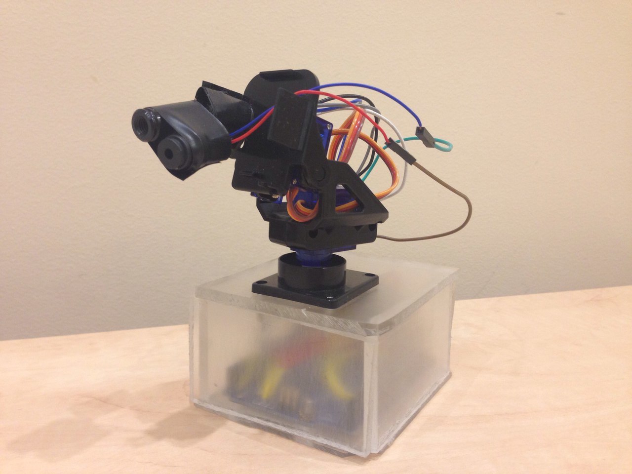
It was the 6th semester of study, we had a serious task before us (because 3 people worked on the project) - it is necessary to make a hardware course project. There were many different ideas: autopilot for the car, night vision device, etc. But the choice fell on the thermal imager, as it was not very simple and not very expensive. And who has not dreamed of his personal thermal imager? In this article we will talk about how we managed to build a thermal imager with pretty good performance at home.
Training
First of all, it was necessary to determine which modules we needed to create an inexpensive thermal imager, but with acceptable characteristics. As a result, after weighing all the pros and cons, it was decided to build a thermal imager based on a servo bracket formed from two servo drives, an IR sensor, a laser for better positioning of the scanned area, and an Arduino to control the device signals. Having decided on the necessary modules, it was necessary to buy it all somewhere. The IR sensor we needed was quite rare and not the cheapest. But all this was found in the famous Chinese online store, it only remained to wait until the parcels arrived.
Circuit design
')
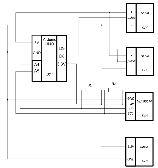
To translate our ideas, we decided to stop at the Arduino UNO. We decided to choose it, since we already had experience with this platform and required the speed of assembly of the device. The circuit uses 4.7 kΩ resistors as pull-up resistors R1 and R2. The MLX90614 bci was chosen as the IR sensor. Mainly due to the fact that he has a narrow field of view, as well as because of its ease of operation. Also, the sensor is quite compact and weighs little, which facilitates the work of servos, which already worked with small jams. For the laser and servo bracket, the first attracted, arduino-compatible modules were selected. Lucky with the laser (and what could be wrong with the laser), and the servos, as already mentioned, did not come very well - they did not respond well to short movements, they often stuck. I had to unwind and lubricate, which slightly improved the situation.
Thermal imaging
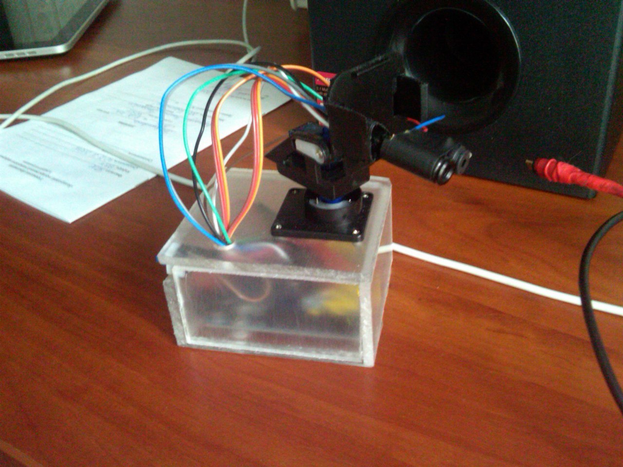
There were no problems with the assembly of the scheme. After the scheme was assembled and tested for efficiency, it became necessary to hide all unnecessary, so that everything looked acceptable and there were no unnecessary questions. There were several options, but since the piece of plexiglass was lying orphaned, the choice was obvious. Therefore, we decided to make a case of plexiglass, in which all the wires and the board will lie, and at the top leave only the servo bracket with the sensors and the laser. As we believe, it turned out beautiful and practical.
The assembly process consisted of polishing plexiglass (very long polishing, so as not to see everything that is behind it). We also decided to fix the servo bracket on the frame. After these manipulations, the entire frame was simply planted on glue.
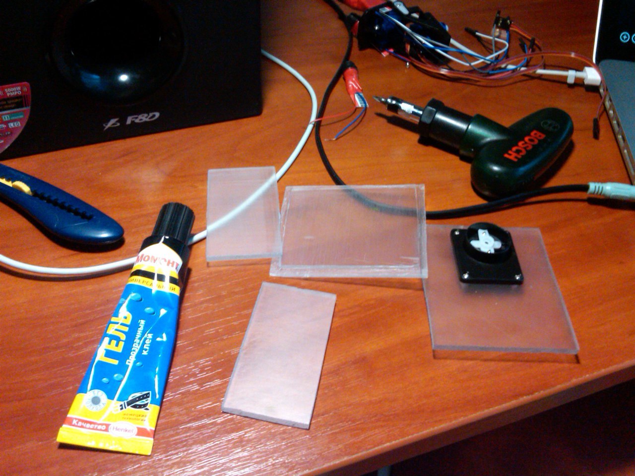
It looked like our device on the way to full readiness:
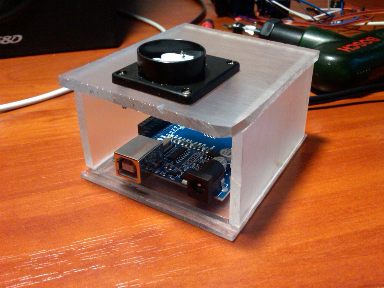
The infrared sensor was connected to the laser and mounted on the servo bracket. This design, despite all the shortcomings, proved to be at a good level. All modules, with the exception of sticking servos, performed the functions assigned to them. As a result, we have such a compact device:
Working with a thermal imager
The easiest way to control a device is to control it from a computer. Power is also provided from the computer. The sensor sends measurement data to the com port. Therefore, a program was written to send commands to the device and read data from the sensor.
The algorithm of the thermal imager is quite simple:
- Open the arduino com-port
- We carry out the positioning of the sensor. To set the scanning area, 2 points are set: bot - the lower left point of the image, mid - the center of the image.
- Run the scan (scanning takes about 2 minutes using the “64x48 pixels” mode)
- We collect the data received from the sensor in an array
- We form the image
Program interface

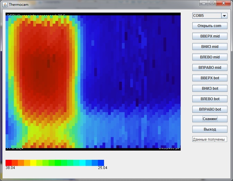
As you can see in the screenshot, the program interface is made in a minimalist style - only everything that is most needed for work. The names of the buttons speak for themselves. When you click on a specific pixel of the heat map, the corresponding temperature will be displayed. Colors for temperature are selected relative to current scan results, i.e. the highest temperature will be indicated in red, and the lowest - in blue, even if these values differ by 2-3 degrees.
How can I check the performance of the thermal imager? Of course, scanning one of its creators! As you can see from the above heat map, the hottest place is the forehead - as much as 33.42 º. There are certain problems with the “range” of the sensor - at a distance of more than 50 cm, the results have a rather large error. But at close range, temperature readings are determined very accurately.
Below you can see another example of the device:

As the scan shows, the temperature of the water inside the glass is at 38 º.
And here is a video demonstrating the operation of the thermal imager:
For those interested, there are links to the source code of the firmware and the application:
Firmware
application
Results
We got a device that can scan small static objects. But there are also disadvantages - it is completely unsuitable for large objects, and if the object moves, then there is not even the slightest chance of getting the right picture. However, the undoubted advantage of this device is its cheapness. All industrial thermal imagers cost several thousand dollars, sometimes tens of thousands. And for the common man, an industrial imager is completely useless, pampered for a week and put it to dust on the shelf. And for home experiments it will be enough and our device, cheap and simple.
Source: https://habr.com/ru/post/394083/
All Articles