WiFi-kettle at home, or how to make an ordinary kettle really smart
Foreword
If you read my previous article ( Running line on Arduino ), then you probably already know that we at the university have the opportunity to do hardware course projects. And I, inspired by my previous work, decided once again to try to do something with my own hands. Only now the topic should have been more serious. By the way, to think about what to do, I started on the winter holidays, that is, before the start of the semester. I wanted to do something interesting and useful at the same time.
')
Search for an idea
Once on a pair of Basic Information Security, we had a topic related to intellectual property and patents. The teacher gave us the task to issue a patent for any device according to all requirements and cited the wifi kettle as an example.
He said - and forgot. And everyone forgot, but in my head this topic remained. And when it came time to think about what to do as coursework in the next semester, I remembered this teapot.
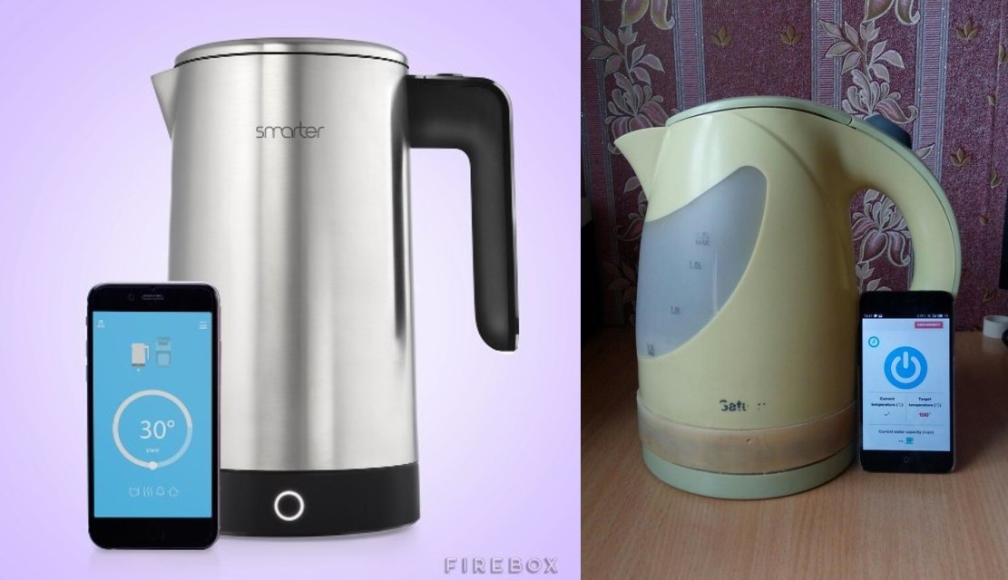
The first thing I decided to see what has already been done. And what was my surprise when I saw that there were only three models of teapots for sale with support for WiFi control, and then two of them belong to the same company. These were Smarter iKettle 1.0 and 2.0 and the Russian Polaris PWK 1792CGL.

Interestingly, ordinary electric kettles are in almost every home, and there are so few smart ones. Comparing the functions offered by the manufacturers of iKettle and Polaris, I made a list of the most necessary. Here is what happened:
- on / off from the smartphone;
- setting any water heating temperature;
- the ability to know the current temperature;
- tracking the current amount of water in the kettle;
- warning and protection against inclusion with a small amount of water;
- set auto-on time;
- readiness alert;
It seems to be real, it's time to get down to business.
Search for the necessary components
Since it was not possible to make a completely new kettle, it was decided to modify the ready-made ordinary electric one. Just at home was an ownerless kettle with a broken switch.
“So, the base is already there” - I thought.
Now it was necessary to look for components for the hardware. Since I already had some experience with Arduino, I decided to implement everything on it. Especially since Arduina herself and the modules for her are inexpensive.
Since I had to insert the whole part of the kettle control inside the kettle, the choice fell on the Arduino Nano. It is small and it has an interface for connecting the cable, unlike the Pro Mini, which needs to be flashed through the UART.

The main component of the wifi kettle is, of course, the wifi module. Searching on the Internet for something affordable and for which many tutorials, ran into ESP8266. Namely, on version 01. I looked at what was cheap (around $ 2) and seemed to be a lot of instructions for connecting. Stopped on it. As for the module itself, the phrase here is good: cheap and cheerful. But more on that later.

To control the temperature needed some waterproof thermal sensor. I found a waterproof NTC thermistor on aliexpress that can withstand temperatures of more than 100 degrees. I also found an example of working with him, so I quickly decided on that too.

It was necessary to decide how to turn on the kettle at a given point in time, of course, it was possible to make a software clock on the Arduino and if the time coincides, turn on the kettle, but it would work unstably, and accidentally reset the program, everything would go wrong. Therefore, a real time clock came to the rescue. Namely DS1307. They have independent power supply (from a 3 V battery), and even on the module on which I stopped, there was a 32K bit EEPROM memory chip, which I used to save on-time.

Oh yeah, since the kettle should now be turned on programmatically, it still took a 1-channel relay.

As for the liquid level sensor, it had to be done manually. Details below.
Of the rest, it still took several resistors of different ratings, a prototype board for tests, a circuit board for proper installation, wiring, a soldering iron with flux and solder, and the lion's share of patience.
Start of development
Since the project is a wifi maker, the first thing I wanted and had to deal with the wifi module. As soon as the message came, he immediately unpacked and began to connect.
Found a bunch of examples on the Internet. All right, voltage regulator 3.3 V, voltage dividers for RX and TX. I collected everything by example, I connect - it did not fly! A heap of text was displayed in the COM port monitor, as it turned out, the module was permanently reset. Does not respond to commands sent by AT. The author of the article works, I do not.
What's the matter? I tried to look for other connection schemes, and this way and that, and the module still either resets or outputs nothing. But everywhere it is written in red: "Do not apply to the 5 V module, otherwise it will fail." So the search for solutions sometimes lasted in the evenings, was already thinking of buying another module, but decided to check the voltage with a multimeter.
It turned out that when the module is connected to 3.3 V, there is a voltage drop below 3.2 V. It seems that, well and good, it falls and falls. I decided to power it from another power source and it turned out that the module works normally when the voltage on it is higher than 3.2 V, and below it is not enough and it is constantly being reset.
In the end, at your own risk, connected to 5 V and everything worked and is still working normally.

There were no such problems with the other components.
Once I figured out wifi, I had to decide what to do with the fluid level sensor. Googling, I found an article in which the author made a soil moisture sensor. When the soil dries out, the resistance of the sensor increases and the voltage at the analog port of Arduino increases. Catching the change in voltage, you can fix the appearance of fluid. To determine the liquid level in my project, instead of two contacts, 6 were used. One of them is connected to the 5 V output, and the rest to the analog inputs and 10 kΩ resistors to GND.
Here is a photo of the tests.


This is the result of the level sensor.

The next thing I tested is the real time clock. But working with them is basically simple. To set the time and get information about him, I used only examples that come bundled with the library for working with DS1307.
As a result, when everything was assembled on a breadboard, such a mixture of wires and modules came out. By the way, on these photos while there is another temperature sensor.

Getting Started
Now all this had to be unsoldered on the circuit board. There is nothing special to comment on, so only the photo. As you can see, another button has been added so that you can turn on the kettle not only from your smartphone, but also in the usual way.


Next, you need to place everything inside the kettle.


An asbestos insert was added to protect all viscera from overheating.

True, the case had to be slightly raised with the help of an additional plastic insert.


Now go to the mobile part.
As for the application, since it was developed under the Android OS, it was originally planned to use Android Studio. But in order to study the new technologies, it was decided to use a ready-made platform for developing programs in the field of the Internet of things. As a result, the choice fell on the company's product Evothings - Evothings Studio.

Here are its main advantages:
- A large number of standard examples of working with various modules (Wifi, Bluetooth);
- development of applications using JS, HTML, CSS, which allows you to write one code that will work equally on Android and iOS OS, i.e. binding to only one platform disappears;
- ease of testing the application: an application is installed on the smartphone to preview its development, and all test messages and error messages are displayed in the program on the computer;
- A large amount of information on the Internet about the development using JS, HTML, CSS;
In this Evothings Studio there was an example of turning on the LED, sending a request to turn on via ESP8266. I decided to take this example as a basis, as there was the most valuable thing for me - communication with the WiFi module via tcp socket. And in the same way as the request to turn on the LED was transmitted, I made the transmission of the request for updating the kettle sensors, to set the on time, set the temperature, etc.
Then he screwed up the notification of readiness and a small amount of water, the good is that everything in our time is easily googled. The result is such an application (a nice thing to make an application interface using CSS):


Brief description of the interaction between the smartphone and the kettle
Communication between the server and the client part is carried out using the WiFi module. When you turn on the kettle control module, the WiFi module starts distributing a network called artKettle. This is done using AT commands on the server side. So, for example, to put the module into the access point mode, it needs to send the command AT + CWMODE = 2. Next, using such commands, you need to assign network settings, allow connection of several devices and get the ip address of the wifi itself.
On the client side, the connection is made via a specific port and at the ip address of the wifi module using chrome.tcp.socket.
After connecting the client to the server, you can control the kettle from your smartphone. Consider an example of the inclusion of a kettle.
When you press the power button in the artKettle application, the corresponding function of the app.kettleOn () is called. Inside this function, two lines are transmitted to the server side:
app.sendString('H'); app.sendString('U'); Next comes the work is already on the side of Arduino. After the arrival of the first line with the character 'H', the following part of the code is executed:
if(message.indexOf("H") >= 0 && waterDetected()) { digitalWrite(POWER_PIN, LOW); IS_ON = true; Serial.println("ON"); sendCIPData(0, "ON"); } First, there is a check whether there is water in the kettle by calling the waterDetected () method. Consider the option when water is present in the kettle.
A low voltage level is applied to the relay control pin, which corresponds to its activation, i.e. power supply circuit closes:
digitalWrite(POWER_PIN, LOW); Then there is the installation of the flag that the kettle is turned on, and the display of the switch-on message on the serial port monitor.
After that, a function is called that sends a response message to the client side that all the activation was successful:
sendCIPData(0, "ON"); On the client side, after checking the incoming message, the power button is set to the On state:
if (buf.substr(0, 2) == "ON") { app.setButtonOn(); } After that, there is a processing of a text message with the symbol 'U', sent from the client to the server. Here, in the same way as the inclusion, the information on the current temperature and the volume of liquid in the kettle is updated.
In this way, two-way communication between the client and the server is organized, so that any of them knows about the state of the other at any time.
Conclusion
As a result of the course project, a modification was developed for an ordinary electric kettle, which allows it to be controlled from a smartphone via wifi. Now this kettle can be attributed to the representatives of the Internet of Things. All the functions were fully implemented, so now this kettle has the following features:
- on / off from the smartphone;
- setting any water heating temperature;
- the ability to find out the current temperature;
- tracking the current volume of water in the kettle;
- warning and protection against inclusion with a small volume of water;
- set the auto-on time;
- notification of readiness;
The advantages of the implemented project is the availability of the element base, because everything you need can be found in the shops of radioelectronic components, the extensibility of the project. Since the kettle has all the necessary sensors installed, it can be modified programmatically and done no worse than its counterparts. Given the versatility of the wifi module used, you can connect it to the Internet and manage the kettle from anywhere in the world, and using the online SMS processing service, you can organize the activation via SMS. Those. the project is still very expandable, there are opportunities for this, but they were not implemented because they were not part of the goals of the project being developed.
Of course there are drawbacks of the project. The first one is the unstable operation of the Wifi module. The module sometimes just loses the network, begins to reset the settings, or simply does not process the incoming signals. And this is a popular problem with users of this module. The second drawback is the lack of mechanical shutdown of the kettle. Switching off is implemented by software, when the boiling point is reached, the circuit is broken using a relay. If suddenly the program fails, the kettle may not turn off. The third drawback is the problem of tracking the heating temperature. For example, if the kettle is turned off at a temperature of 60 degrees, the heating ten will continue to give off heat, and after a while the water temperature will already be about 70 degrees. But this is corrected by making adjustments to the program.
Source: https://habr.com/ru/post/393785/
All Articles